CN201339620Y - Hydraulic system of full hydraulic metal plate straightener - Google Patents
Hydraulic system of full hydraulic metal plate straightener Download PDFInfo
- Publication number
- CN201339620Y CN201339620Y CNU2009201013253U CN200920101325U CN201339620Y CN 201339620 Y CN201339620 Y CN 201339620Y CN U2009201013253 U CNU2009201013253 U CN U2009201013253U CN 200920101325 U CN200920101325 U CN 200920101325U CN 201339620 Y CN201339620 Y CN 201339620Y
- Authority
- CN
- China
- Prior art keywords
- hydraulic
- servo
- valves
- hydraulic system
- valve
- Prior art date
- Legal status (The legal status is an assumption and is not a legal conclusion. Google has not performed a legal analysis and makes no representation as to the accuracy of the status listed.)
- Expired - Fee Related
Links
- 239000002184 metal Substances 0.000 title claims abstract description 12
- 239000012530 fluid Substances 0.000 claims 1
- 239000003921 oil Substances 0.000 abstract description 23
- 239000010720 hydraulic oil Substances 0.000 abstract description 3
- 229910000831 Steel Inorganic materials 0.000 description 2
- 238000010586 diagram Methods 0.000 description 2
- 239000010959 steel Substances 0.000 description 2
- 238000000034 method Methods 0.000 description 1
- 230000008092 positive effect Effects 0.000 description 1
Images


Landscapes
- Fluid-Pressure Circuits (AREA)
Abstract
Description
技术领域 technical field
本实用新型属于金属板矫正机技术领域,具体涉及一种全液压金属板矫正机液压系统。The utility model belongs to the technical field of metal plate straightening machines, in particular to a hydraulic system of a fully hydraulic metal plate straightening machine.
背景技术 Background technique
全液压金属板矫正机是通过液压系统对伺服缸进行控制来实现对矫直板的质量要求。目前国内外设计的全液压金属板矫正机的液压系统如图1所示:该系统中压力油从压力油管路S通过常开电磁球阀1.1、1.2先打开液控单向阀4.1、4.2、4.3、4.4,控制伺服比例阀2.1、2.2的阀芯动作,使压力油从伺服比例阀2.1、2.2的E、E’口连接伺服缸7.1、7.2的无杆腔B、B’,伺服比例阀2.1、2.2的F、F’口堵死,同时压力油经过三通减压阀9减压到设定压力后与伺服缸7.1、7.2的有杆腔A、A’连接。该液压系统不能提高伺服缸对指令的响应速度,无法满足矫正机高质量、高效率生产要求。The full hydraulic metal plate straightening machine realizes the quality requirements for straightening plates by controlling the servo cylinder through the hydraulic system. The hydraulic system of the fully hydraulic metal plate straightening machine designed at home and abroad is shown in Figure 1: in this system, the pressure oil passes through the normally open electromagnetic ball valve 1.1, 1.2 from the pressure oil pipeline S to open the hydraulic control check valve 4.1, 4.2, 4.3 first. , 4.4, control the spool action of the servo proportional valve 2.1, 2.2, so that the pressure oil is connected to the rodless cavity B, B' of the servo cylinder 7.1, 7.2 from the E, E' ports of the servo proportional valve 2.1, 2.2, and the servo proportional valve 2.1 , 2.2 F, F' ports are blocked, and the pressure oil is decompressed to the set pressure through the three-way pressure reducing valve 9 at the same time, and is connected with the rod cavity A, A' of the servo cylinder 7.1, 7.2. The hydraulic system cannot improve the response speed of the servo cylinder to instructions, and cannot meet the high-quality and high-efficiency production requirements of the straightening machine.
实用新型内容 Utility model content
本实用新型的目的是为全液压金属板矫正机提供一种新的液压系统,可以有效地克服现有技术存在的缺点。The purpose of the utility model is to provide a new hydraulic system for a fully hydraulic metal plate straightening machine, which can effectively overcome the shortcomings of the prior art.
本实用新型是这样实现的:如图2所示:压力油从压力油管路S通过高压蓄能器6.1、6.2、常开电磁球阀1.1、1.2、液控单向阀4.1、4.2、4.4、4.5、伺服比例阀2.1、2.2的E、E’口连接伺服缸7.1、7.2的无杆腔B、B’,电磁溢流阀3.1、3.2与伺服缸7.1、7.2的无杆腔B、B’连通,伺服缸7.1、7.2的有杆腔A、A’经液控单向阀4.3、4.6与伺服比例阀2.1、2.2的F、F’口相连,液压油经回油蓄能器8.1、8.2、插装式单向阀5.1、5.2流回回油管路L,通过控制伺服缸7.1、7.2的无杆腔和有杆腔来提高伺服缸7.1、7.2对指令的响应速度,以提高全液压金属板矫正机矫正钢板的质量。The utility model is realized in this way: as shown in Figure 2: the pressure oil passes through the high-pressure accumulator 6.1, 6.2, the normally open electromagnetic ball valve 1.1, 1.2, the hydraulic control check valve 4.1, 4.2, 4.4, 4.5 from the pressure oil pipeline S , The ports E and E' of the servo proportional valves 2.1 and 2.2 are connected to the rodless chambers B and B' of the servo cylinders 7.1 and 7.2, and the electromagnetic overflow valves 3.1 and 3.2 are connected to the rodless chambers B and B' of the servo cylinders 7.1 and 7.2 , the rod chambers A and A' of the servo cylinders 7.1 and 7.2 are connected to the F and F' ports of the servo proportional valves 2.1 and 2.2 through the hydraulic control check valves 4.3 and 4.6, and the hydraulic oil passes through the oil return accumulators 8.1 and 8.2, The plug-in check valve 5.1, 5.2 flows back to the oil return line L, and improves the response speed of the servo cylinder 7.1, 7.2 to the command by controlling the rodless chamber and the rod chamber of the servo cylinder 7.1, 7.2, so as to improve the full hydraulic metal plate straightening machine to correct the quality of the steel plate.
本实用新型优点及积极效果是:The utility model advantage and positive effect are:
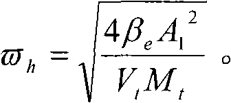
与现有技术图1比较,本实用新型去掉了三通减压阀9、溢流阀10、液控单向阀11、常闭电磁球阀12、背压蓄能器13、板式溢流阀14,同时本实用新型采用伺服比例阀2.1、2.2控制伺服缸7.1、7.2的无杆腔B、B’和有杆腔A、A’,其好处是能够提高液压系统的固有频率和伺服缸的响应速度,比如按图1建立的液压系统固有频率为:
附图说明 Description of drawings
图1为现有技术全液压金属板矫正机液压系统图Fig. 1 is the hydraulic system diagram of the prior art fully hydraulic metal plate leveling machine
图2为本实用新型液压系统图Fig. 2 is the hydraulic system diagram of the utility model
图中in the picture
1.1、1.2——常开电磁球阀 2.1、2.2——伺服比例阀 3.1、3.2——电磁溢流阀 4.1、4.2、4.3、4.4、4.5、4.6——液控单向阀 5.1、5.2——插装式单向阀 6.1、6.2——高压蓄能器 7.1、7.2——伺服缸 8.1、8.2——回油蓄能器 9——三通减压阀 10——溢流阀 11——液控单向阀12——常闭电磁球阀 13——背压蓄能器 14——板式溢流阀1.1, 1.2——Normal Open Solenoid Ball Valve 2.1, 2.2——Servo Proportional Valve 3.1, 3.2——Electromagnetic Relief Valve 4.1, 4.2, 4.3, 4.4, 4.5, 4.6——Hydraulic Control Check Valve 5.1, 5.2——Plug Installed check valve 6.1, 6.2——High pressure accumulator 7.1, 7.2——Servo cylinder 8.1, 8.2——Oil return accumulator 9——Three-way pressure reducing valve 10——
具体实施方式 Detailed ways
如图2所示,压力油从压力油管路S通过常开电磁球阀1.1、1.2先打开液控单向阀4.1、4.2、4.3、4.4、4.5、4.6,压力油进入到伺服比例阀2.1、2.2的压力油口P,同时与高压蓄能器6.1、6.2接通,控制伺服比例阀2.1、2.2的阀芯动作使压力油从伺服比例阀2.1、2.2的E、E’口经液控单向阀4.2、4.5进入伺服缸7.1、7.2的无杆腔B、B’,此时伺服缸7.1、7.2的有杆腔A、A’经液控单向阀4.3、4.6与伺服比例阀2.1、2.2的F、F’口接通,F、F’口与伺服比例阀2.1、2.2的回油口T接通,液压油从T口经回油蓄能器8.1、8.2、插装式单向阀5.1、5.2流回回油管路L,伺服缸7.1、7.2的活塞杆伸出;控制伺服比例阀2.1、2.2的阀芯动作使压力油从伺服比例阀2.1、2.2的F、F’口经液控单向阀4.3、4.6进入伺服缸7.1、7.2的有杆腔A、A’,此时伺服缸7.1、7.2的无杆腔B、B’经液控单向阀4.2、4.5与伺服比例阀2.1、2.2的E、E’口接通,E、E’与伺服比例阀2.1、2.2的回油口T接通,液压油从T口经回油蓄能器8.1、8.2、插装式单向阀5.1、5.2流回回油管路L,伺服缸2.1、2.2的活塞杆缩回。As shown in Figure 2, the pressure oil passes through the normally open electromagnetic ball valves 1.1 and 1.2 from the pressure oil pipeline S and first opens the hydraulic control check valves 4.1, 4.2, 4.3, 4.4, 4.5, 4.6, and the pressure oil enters the servo proportional valves 2.1 and 2.2 The pressure oil port P of the servo proportional valve 2.1, 2.2 is connected to the high-pressure accumulator 6.1, 6.2 at the same time, and the valve core action of the servo proportional valve 2.1, 2.2 is controlled to make the pressure oil flow from the E, E' ports of the servo proportional valve 2.1, 2.2 through the hydraulic control one-way The valves 4.2 and 4.5 enter the rodless chambers B and B' of the servo cylinders 7.1 and 7.2. At this time, the rod chambers A and A' of the servo cylinders 7.1 and 7.2 pass through the hydraulic control check valves 4.3 and 4.6 and the servo proportional valves 2.1 and 2.2 The ports F and F' of the valve are connected, and the ports F and F' are connected to the oil return port T of the servo proportional valve 2.1 and 2.2. 5.1, 5.2 flow back to the oil return line L, and the piston rods of the servo cylinders 7.1, 7.2 extend out; control the spool movement of the servo proportional valves 2.1, 2.2 so that the pressure oil flows from the F, F' ports of the servo proportional valves 2.1, 2.2 through the hydraulic control The one-way valves 4.3, 4.6 enter the rod chambers A, A' of the servo cylinders 7.1, 7.2. At this time, the rodless chambers B, B' of the servo cylinders 7.1, 7.2 pass through the hydraulic control check valves 4.2, 4.5 and the servo proportional valve 2.1 , 2.2 E, E' ports are connected, E, E' are connected to the oil return port T of the servo proportional valve 2.1, 2.2, and the hydraulic oil passes through the oil return accumulator 8.1, 8.2 from the T port, and the plug-in one-way The valves 5.1, 5.2 flow back into the return line L, and the piston rods of the servo cylinders 2.1, 2.2 are retracted.
Claims (1)
Priority Applications (1)
| Application Number | Priority Date | Filing Date | Title |
|---|---|---|---|
| CNU2009201013253U CN201339620Y (en) | 2009-01-13 | 2009-01-13 | Hydraulic system of full hydraulic metal plate straightener |
Applications Claiming Priority (1)
| Application Number | Priority Date | Filing Date | Title |
|---|---|---|---|
| CNU2009201013253U CN201339620Y (en) | 2009-01-13 | 2009-01-13 | Hydraulic system of full hydraulic metal plate straightener |
Publications (1)
| Publication Number | Publication Date |
|---|---|
| CN201339620Y true CN201339620Y (en) | 2009-11-04 |
Family
ID=41235167
Family Applications (1)
| Application Number | Title | Priority Date | Filing Date |
|---|---|---|---|
| CNU2009201013253U Expired - Fee Related CN201339620Y (en) | 2009-01-13 | 2009-01-13 | Hydraulic system of full hydraulic metal plate straightener |
Country Status (1)
| Country | Link |
|---|---|
| CN (1) | CN201339620Y (en) |
Cited By (3)
| Publication number | Priority date | Publication date | Assignee | Title |
|---|---|---|---|---|
| CN103541938A (en) * | 2013-09-11 | 2014-01-29 | 昆山新金福精密电子有限公司 | Hydraulic system |
| CN113864254A (en) * | 2021-08-20 | 2021-12-31 | 宣化钢铁集团有限责任公司 | Withdrawal and straightening hydraulic control device |
| CN115962173A (en) * | 2022-12-08 | 2023-04-14 | 山东泰丰智能控制股份有限公司 | Hydraulic system of rolling mill |
-
2009
- 2009-01-13 CN CNU2009201013253U patent/CN201339620Y/en not_active Expired - Fee Related
Cited By (3)
| Publication number | Priority date | Publication date | Assignee | Title |
|---|---|---|---|---|
| CN103541938A (en) * | 2013-09-11 | 2014-01-29 | 昆山新金福精密电子有限公司 | Hydraulic system |
| CN113864254A (en) * | 2021-08-20 | 2021-12-31 | 宣化钢铁集团有限责任公司 | Withdrawal and straightening hydraulic control device |
| CN115962173A (en) * | 2022-12-08 | 2023-04-14 | 山东泰丰智能控制股份有限公司 | Hydraulic system of rolling mill |
Similar Documents
| Publication | Publication Date | Title |
|---|---|---|
| CN101463846B (en) | A full hydraulic metal plate leveling machine hydraulic system | |
| CN201580012U (en) | Hydraulic control system for hydraulic press | |
| CN103321984B (en) | Hydraulic control system for differential oil compensation with electric-hydraulic proportional cartridge valves | |
| CN203248431U (en) | Unloading valve, hydraulic oil cylinder oil return backpressure unloading device and engineering machine | |
| CN205207311U (en) | Meso position burden flow valve, swing arm energy -saving control system and excavator | |
| CN102418719B (en) | Energy-saving hydraulic station | |
| CN204739038U (en) | Servo hydraulic system of sheet material bender | |
| CN206830554U (en) | Align machine hydraulic system and apply its straightener | |
| CN202451485U (en) | Hydraulic synchronization independent control device, synchronous hydraulic system and crane | |
| CN205089714U (en) | Pneumatic cylinder oil piping system of numerical control hydraulic pressure sheet material tubulation make -up machine | |
| CN203892276U (en) | Hydraulic ejection system | |
| CN102304931B (en) | Hydraulic energy-saving control system and method for loader movable arm | |
| CN202056126U (en) | Double-cylinder control hydraulic circuit capable of avoiding hopper swing and changing oil automatically | |
| CN201735758U (en) | Stepping cold bed hydraulic control device for continuous casting machine | |
| CN201275860Y (en) | Opening and closing die hydraulic circuit system of injection moulding machine | |
| CN205466701U (en) | Ceramic brick machine's hydraulic drive system | |
| CN206017297U (en) | A kind of hydraulic circuit for controlling the High-Speed Automatic variable of two-chamber oil cylinder | |
| CN204054563U (en) | A kind of use two cartridge valve controlled liquefaction cylinders differential and buffering hydraulic circuit | |
| CN203362682U (en) | Differential oil supplementing hydraulic control device of electro-hydraulic proportional cartridge valve | |
| CN206582193U (en) | A kind of hydraulic system for being applied to 40~160t common bending machines | |
| CN202012095U (en) | Movable arm hydraulic energy saving control device for loading machine | |
| CN203082269U (en) | Magnetic valve for shoe machine | |
| CN202418074U (en) | Hydraulic cartridge valve group control device for concrete pump truck | |
| CN101941305A (en) | Hydraulic system of 4800T press machine | |
| CN202531524U (en) | Hydraulic system for hydraulic die forging hammer |
Legal Events
| Date | Code | Title | Description |
|---|---|---|---|
| C14 | Grant of patent or utility model | ||
| GR01 | Patent grant | ||
| C17 | Cessation of patent right | ||
| CF01 | Termination of patent right due to non-payment of annual fee |
Granted publication date: 20091104 Termination date: 20120113 |