CN201329395Y - Wire drawing and winding machine system - Google Patents
Wire drawing and winding machine system Download PDFInfo
- Publication number
- CN201329395Y CN201329395Y CNU2008201824704U CN200820182470U CN201329395Y CN 201329395 Y CN201329395 Y CN 201329395Y CN U2008201824704 U CNU2008201824704 U CN U2008201824704U CN 200820182470 U CN200820182470 U CN 200820182470U CN 201329395 Y CN201329395 Y CN 201329395Y
- Authority
- CN
- China
- Prior art keywords
- wire drawing
- fixture
- support
- driven
- hole
- Prior art date
- Legal status (The legal status is an assumption and is not a legal conclusion. Google has not performed a legal analysis and makes no representation as to the accuracy of the status listed.)
- Expired - Lifetime
Links
Images


Landscapes
- Wire Processing (AREA)
Abstract
本实用新型公开了一种拉丝缠绕系统,本系统采用的技术方案是:(1)采用长摇臂加轴承结构自动调整拉伸方向与校准孔轴向与接近一致;(2)采用类似梯子状工装结构,使得褪掉缠绕后弹簧变得非常容易;(3)采用超高耐磨性材料设计校准孔,根据校准孔大小来控制拉伸比例;(4)采用两个伺服电机为拉伸和缠绕工艺提供动力;(5)采用PLC工业控制技术控制整套系统的运行,实现精确定位,并且程序可以方便更改,满足不同类型产品的技术要求;(6)采用触摸屏装置实现人机交互功能,易于由操作人员改动各个运行参数。整套系统实用、可靠,完全可以实现大批量生产,大大降低了工人的劳动强度并且提高了产品的一致性和均匀性。
The utility model discloses a wire drawing winding system. The technical solution adopted by the system is: (1) adopting a long rocker arm plus a bearing structure to automatically adjust the stretching direction to be consistent with the axial direction of the calibration hole; (2) adopting a ladder-like The tooling structure makes it very easy to remove the wound spring; (3) The calibration hole is designed with ultra-high wear-resistant materials, and the stretching ratio is controlled according to the size of the calibration hole; (4) Two servo motors are used for stretching and The power is provided by the winding process; (5) PLC industrial control technology is used to control the operation of the whole system to achieve precise positioning, and the program can be easily changed to meet the technical requirements of different types of products; (6) The touch screen device is used to realize the human-computer interaction function, which is easy Each operating parameter is changed by the operator. The entire system is practical and reliable, and can completely realize mass production, greatly reducing the labor intensity of workers and improving the consistency and uniformity of products.
Description
技术领域 technical field
本实用新型属于针对金属减振器生产的机械设计领域,具体涉及一种自动化拉丝缠绕机系统。The utility model belongs to the field of mechanical design aimed at the production of metal shock absorbers, and in particular relates to an automatic wire drawing winding machine system.
背景技术 Background technique
金属减振器是为了解决高温、低温、高压、高真空及剧烈振动等环境下的阻尼、减振、过滤、密封、热传导等问题研制开发出的金属橡胶构件,广泛应用于航空航天领域。金属减振器的生产工艺非常特殊,整个生产过程非常复杂,现阶段有很多项工艺流程仍为手工操作,例如按一定比例拉伸弹簧和将拉伸后的弹簧按一定模式缠绕。手工参与生产有很多缺点:(1)生产效率低;(2)容易出现废品;(3)产品的一致性与均匀性很难保证。为了满足大批量生产的要求以及进一步提高产品质量,迫切需要研究相关设备逐步取代手工操作,实现机器自动化生产。Metal shock absorbers are metal rubber components developed to solve problems such as damping, vibration reduction, filtering, sealing, and heat conduction in high temperature, low temperature, high pressure, high vacuum, and severe vibration environments. They are widely used in the aerospace field. The production process of metal shock absorbers is very special, and the entire production process is very complicated. At this stage, many processes are still manual operations, such as stretching the spring according to a certain ratio and winding the stretched spring according to a certain pattern. Manual production has many disadvantages: (1) low production efficiency; (2) easy to produce waste products; (3) it is difficult to guarantee the consistency and uniformity of products. In order to meet the requirements of mass production and further improve product quality, it is urgent to study related equipment to gradually replace manual operations and realize automatic production of machines.
近些年来,为了实现金属减振器的自动化生产,国内外开展了多项研究,并取得了多项成果;但是由于生产工艺的特殊性,许多问题仍然没有解决。国内某大学曾研发出一种螺旋卷定螺距拉伸装置,它利用两个滚轮速度差的原理来实现按一定比例将弹簧拉伸,但与后续工艺不能衔接,后续的缠绕工艺仍然为手工操作。In recent years, in order to realize the automatic production of metal shock absorbers, many researches have been carried out at home and abroad, and many achievements have been made; however, due to the particularity of the production process, many problems still remain unsolved. A domestic university has developed a spiral winding fixed-pitch stretching device, which uses the principle of the speed difference between two rollers to stretch the spring in a certain proportion, but it cannot be connected with the subsequent process, and the subsequent winding process is still manual. .
发明内容 Contents of the invention
本实用新型的目的是:提供一套自动化的拉丝缠绕机系统。The purpose of the utility model is to provide a set of automatic wire drawing winding machine system.
实现本实用新型目的的技术方案:一种拉丝缠绕机系统包括:拉丝机构、缠绕机构和自动控制系统。拉丝机构包括伺服电机、丝杆、导轨和摆线装置。伺服电机与丝杆连接,摆线装置通过其底部的螺纹通孔与丝杆连接。在拉丝机构的附近设有缠绕机构,缠绕机构包括伺服电机、夹具和导轨。伺服电机由支座支撑并与主动卡具连接,主动卡具的卡槽内插着主动板。主动板和与之对应的从动板之间设有“梯形”夹具。从动板另一端有一锥形轴,其轴处于从动卡具的中心线上的凹槽内,并可在其内转动。从动卡具的另一端通过轴承与底部设有“工形”滑槽的从动支座连接,从动支座通过其底部的“工形”滑槽与导轨连接,并可以沿着导轨移动,通过从动支座上的定位螺钉固定其位置。自动控制系统通过导线分别与伺服电机相连。自动控制系统经过计算机编程后的PLC主控单位发高速脉冲信号给伺服电机的驱动器,控制电机的转速;PLC控制单位设有启动、停止、继续和复位功能。Technical solution to realize the purpose of the utility model: a wire drawing and winding machine system includes: a wire drawing mechanism, a winding mechanism and an automatic control system. The drawing mechanism includes a servo motor, a screw, a guide rail and a cycloid device. The servo motor is connected with the screw mandrel, and the cycloid device is connected with the screw mandrel through the threaded through hole at the bottom. A winding mechanism is arranged near the wire drawing mechanism, and the winding mechanism includes a servo motor, a clamp and a guide rail. The servo motor is supported by the support and connected with the active fixture, and the active plate is inserted in the slot of the active fixture. A "trapezoidal" clamp is provided between the active plate and the corresponding driven plate. There is a tapered shaft at the other end of the driven plate, and its shaft is in the groove on the center line of the driven fixture, and can rotate therein. The other end of the driven fixture is connected to the driven support with the "I-shaped" chute at the bottom through the bearing, and the driven support is connected to the guide rail through the "I-shaped" chute at the bottom, and can move along the guide rail , its position is fixed by the set screw on the driven support. The automatic control system is respectively connected with the servo motors through wires. The PLC main control unit of the automatic control system after computer programming sends a high-speed pulse signal to the driver of the servo motor to control the speed of the motor; the PLC control unit is equipped with start, stop, continue and reset functions.
上述的摆线装置包括“L”形的长摇臂、下端盖、垫片和轴。“L”形长摇臂的竖直臂上开有一个阶梯形通孔,在通孔半径较小的处放置一个半径稍大、中心开有校准孔的垫片,并用上端盖压紧垫片,通过螺钉固定。长摇臂处于水平位置的长臂与轴连接,轴通过轴承与轴承支座连接,长摇臂可以轴转动;轴承支座的下部设有螺纹通孔。The above-mentioned cycloid device includes an "L"-shaped long rocker arm, a lower end cover, a spacer and a shaft. There is a stepped through-hole on the vertical arm of the "L"-shaped long rocker arm. Place a gasket with a slightly larger radius and a calibration hole in the center at the place where the radius of the through-hole is smaller, and press the gasket with the upper end cover. , fixed by screws. The long arm of the long rocker arm in the horizontal position is connected with the shaft, and the shaft is connected with the bearing support through the bearing, and the long rocker arm can rotate around the shaft; the bottom of the bearing support is provided with a threaded through hole.
上述的夹具包括夹具梁、支撑轴和支撑杆,夹具梁为一对双层长杆,两层之间有一定的间隙,夹具梁的两端开有半圆形凹槽,支撑杆的两端处于夹具梁的双层间隙内并通过均匀分布在夹具梁上的支撑轴连接,呈“梯子”状的工装结构,夹具梁通过支撑杆可以相对搓动。The above-mentioned fixture includes a fixture beam, a support shaft and a support rod. The fixture beam is a pair of double-layer long rods with a certain gap between the two layers. There are semicircular grooves at both ends of the fixture beam, and the two ends of the support rod Located in the double-layer gap of the fixture beam and connected by support shafts evenly distributed on the fixture beam, it is a "ladder"-shaped tooling structure, and the fixture beam can relatively rub through the support rod.
上述的垫片的材料为高速工具钢W12Cr4V5Co5。The above gasket is made of high speed tool steel W12Cr4V5Co5.
上述的PLC主控单位与触摸屏控制面板无缝连接,触摸屏控制面板上可显示和设置伺服电机的转速、摆线装置的启动位置,执行启动、停止、继续和复位命令。The above-mentioned PLC main control unit is seamlessly connected with the touch screen control panel. The speed of the servo motor and the start position of the cycloid device can be displayed and set on the touch screen control panel, and the start, stop, continue and reset commands can be executed.
本实用新型的有益效果:本套系统利用特殊小孔拉伸和PLC工业控制技术可以将弹簧拉伸与缠绕两项工艺流程同时由手工操作变为机器自动化,并将这两步有效衔接起来。某金属减振器生产车间已经利用本套设备生产产品,并由振动试验室进行了性能检验,结果表明,本套设备在提高工作效率的同时,较大程度提高了金属减振器产品的一致性和均匀性。Beneficial effects of the utility model: the system uses special small hole stretching and PLC industrial control technology to simultaneously change the two processes of spring stretching and winding from manual operation to machine automation, and effectively connect these two steps. A metal shock absorber production workshop has used this set of equipment to produce products, and the performance test has been carried out by the vibration laboratory. The results show that this set of equipment can greatly improve the consistency of metal shock absorber products while improving work efficiency. and uniformity.
附图说明 Description of drawings
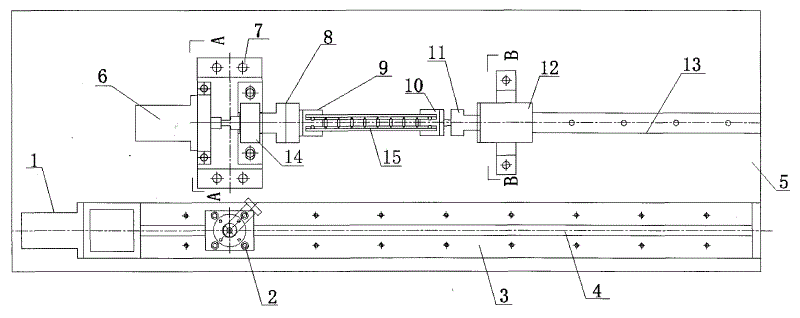
图1为本实用新型的一种拉丝缠绕机系统总体结构示意图。Fig. 1 is a schematic diagram of the overall structure of a wire drawing and winding machine system of the present invention.
图2为摆线装置结构示意图。Figure 2 is a schematic diagram of the structure of the cycloid device.
图3为电机支座机构A-A向剖面图。Fig. 3 is an A-A sectional view of the motor support mechanism.
图4主动板俯视图。Figure 4 Top view of the active board.
图5为主动板主视图。Figure 5 is a front view of the active board.
图6为主动板左视图。Figure 6 is a left side view of the active board.
图7为差动式夹具结构示意图。Fig. 7 is a schematic structural diagram of a differential clamp.
图8为差动式夹具有错位差动时的结构示意。Fig. 8 is a schematic diagram of the structure of the differential clamp with misalignment differential.
图9为差动式夹具侧视图。Figure 9 is a side view of the differential clamp.
图10为从动支座结构示意图。Figure 10 is a schematic diagram of the structure of the driven support.
图11为从动支座B-B向剖面图。Fig. 11 is a cross-sectional view of the driven support on B-B direction.
图12为自动控制系统原理图。Figure 12 is a schematic diagram of the automatic control system.
图中:1-伺服电机;2-摆线装置;3-导轨;4-丝杆;5-工作台;6-伺服电机;7-支座;8-主动卡具;9-主动板;10-从动板;11-从动卡具;12-从动支座;13-导轨;14-支座;15-夹具;16-垫片;17-轴;18-长摇臂;19-螺母;20-下端盖;21-轴承;22-螺母;23-轴承座;24-上端盖;25-校准孔;26-轴承;27-电机支座;28-支撑轴;29-夹具梁;30-支撑杆;31-螺母;32-预装盖;33-轴承;34-螺钉;35-端盖。In the figure: 1-servo motor; 2-cycloidal device; 3-guide rail; 4-screw; 5-table; 6-servo motor; 7-support; 8-active fixture; 9-active plate; - driven plate; 11- driven fixture; 12- driven support; 13- guide rail; 14- support; 15- fixture; 16- spacer; 17- shaft; 18- long rocker arm; ;20-lower end cover; 21-bearing; 22-nut; 23-bearing seat; 24-upper end cover; 25-calibration hole; 26-bearing; 27-motor support; 28-support shaft; -support rod; 31-nut; 32-pre-installed cover; 33-bearing; 34-screw; 35-end cover.
具体实施方式 Detailed ways
下面结合附图详细说明本实用新型的一种拉丝缠绕机系统。A wire drawing and winding machine system of the present invention will be described in detail below in conjunction with the accompanying drawings.
如图1所示,该实用新型的一种拉丝缠绕机系统包括:拉丝机构、缠绕机构和自动控制系统,拉丝机构、缠绕机构固定在工作台5上。拉丝机构包括伺服电机1、导轨3、丝杆4和摆线装置2。摆线装置2的结构如图2所示,包括“L”形的长摇臂18、垫片16、上端盖24、下端盖20和轴承座23。在“L”形的长摇臂18的竖直臂上开有一个阶梯形通孔,在阶梯形通孔半径较小的位置处放置一个半径稍大的中心有校准孔25的垫片16,垫片16材料为高速工具钢W12Cr4V5Co5,上端盖24压紧垫片16并通过螺钉固定好。“L”形的长摇臂18处于水平位置的长臂上设一通孔,通过阶梯形的轴17连接,并用螺母19拧紧固定死,轴17的下部通过轴承21与中部开有阶梯形的通孔轴承座23连接,轴承21的上部用下端盖20通过螺钉顶紧固定,这样摆线装置2的长摇臂可以轴17为中心自由摆动。在轴承座23的下部还设有与丝杆4相配的螺纹通孔,丝杆4穿过螺纹通孔与轴承座23连接,固定在工作台5上的伺服电机1与丝杆4连接,带动丝杆4转动从而使摆线装置沿着丝杆在导轨3上运动。缠绕机构处于拉丝机构的附近,缠绕机构包括伺服电机6、夹具15和导轨13。伺服电解6为商用电机,处于支座7上其轴通过电机支座27上的轴承26与处于支座14上的主动卡具8连接。主动卡具8的另一端开有一个与主动板9相匹配的卡槽连接着主动板9。如图4、5和6所示,主动板9呈一级“台阶”结构,在一端为与主动卡具8的卡槽匹配的插板,另一端的板上开有两个螺纹孔,用于固定夹具15。夹具15的结构如图7和8所示,由一对夹具梁29、8个支撑杆30和8对均匀分布在夹具梁29上的支撑轴28组成。在实际使用时,夹具15中支撑轴28和支撑杆29的数量可以根据夹具梁的具体长度来变化。如图7、8和9所示,夹具梁29的结构比较特殊,为一个薄直角梯形的双层的长杆结构,并且双层间有一定的间距,用于夹持支撑杆30、支撑杆30处于其中并通过支撑轴28销好,两端设有半圆形的螺纹孔,通过螺钉可以固定在主动板9和从动板10上。在进行缠绕时,该夹具15的结构如图7所示,但是当弹簧缠绕完成,卸下螺钉取下夹具15,错动夹具梁29使夹具15变为如图8所示的情况,此时便可以很方便的抽出缠绕好的弹簧。如图1所示,从动板10的结构与主动板9相似也为一级“台阶”结构,一端的板上开有两个螺纹孔,用于固定夹具15,但是另一端为一个圆锥形的支撑轴,该支撑轴卡在从动卡具11中心的凹槽内,并且可以在凹槽内转动。如图10所示,从动卡具11通过轴承33与固定在从动支座12上,轴承33的一端通过螺母31拧紧固定,另一端通过端盖35顶紧并用螺钉34拧紧固定。如图11所示,从动支座12的下部设有一个“工形”的滑槽,该滑槽刚好与设置在工作台5上的导轨13匹配,并卡在导轨13上,可沿着导轨13移动。在实际应用时,由于夹具15的长度不同通过移动从动支座12来调节,移动到合适的位置后,通过设置在从动支座两侧的定位螺钉固定在工作台5上,另外如图10所示,在从动支座12上还开设有一个孔,用预装盖32盖上以便于调节拧紧螺母31。As shown in FIG. 1 , a wire drawing and winding machine system of the utility model includes: a wire drawing mechanism, a winding mechanism and an automatic control system, and the wire drawing mechanism and the winding mechanism are fixed on a
该拉丝缠绕系统控制通过导线与伺服电机1和6连接,自动控制系统的结构原理如图12所示。PLC为主控单位,其经过计算机编程后内置固化。PLC发高速脉冲信号给伺服电机1和6的驱动器,驱动器采用位置控制模式,一个脉冲使伺服电机1和6转过一定的角度,高速脉冲信号的周期控制着电机1和6转速的快慢,角度大小、脉冲信号的周期均可以在伺服驱动器中设置。协调两个电机1和6的转速使夹具梁15的绕线速度和摆线装置2的摆线速度,使拉丝机构和缠绕机构配合完成弹簧的拉丝缠绕工作。PLC控制单位设有启动、停止、继续和复位等功能,可以控制系统的启动、停止和复位等。有一个触摸屏控制面板与PLC数据无缝连接,触摸屏控制面板上可显示和设置伺服电机1和6的转速、摆线装置2的启动位置,执行启动、停止、继续和复位命令。通过触摸屏控制面板便可以进行人机交互,完成弹簧自动拉丝缠绕工作。The wire drawing and winding system is controlled to be connected with the servo motors 1 and 6 through wires, and the structural principle of the automatic control system is shown in FIG. 12 . PLC is the main control unit, which is built-in and solidified after computer programming. The PLC sends high-speed pulse signals to the drivers of servo motors 1 and 6. The drivers adopt position control mode. One pulse makes servo motors 1 and 6 rotate through a certain angle. The period of the high-speed pulse signal controls the speed and angle of the motors 1 and 6. The size and period of the pulse signal can be set in the servo driver. Coordinate the rotating speeds of the two motors 1 and 6 to make the winding speed of the
该拉丝缠绕机构的工作过程如下:(1)启动整套系统;(2)按控制面板上的“复位”按钮,确保摆线装置2和缠绕机构在合适位置;(3)将要拉伸缠绕的弹簧穿过垫片16的校准孔25,并且将弹簧布置在夹具15上;(4)按控制面板上的“启动”按钮,系统开始运行,伺服电机1和6开始运转分别带动摆线装置2移动和夹具15转动,实现弹簧的拉伸和缠绕,在运行过程中由于摆线装置2配合夹具15协调运动,且摆线装置2可以轴17为中心摆动,因此可以很好的保持弹簧拉丝的质量和准确性;(5)如果中途想停止,可使用“停止”按钮使系统暂停,之后按“继续”按钮继续工作;(6)缠绕完毕后按控制面板上的“停止”按钮;(7)卸下夹具15错动,取下缠绕好的弹簧或者更换新夹具,重新按控制面板上的“复位”按钮再次运行整套系统;(8)将卸下的夹具相对搓动之后,便可褪下缠绕好的弹簧。The working process of the wire drawing winding mechanism is as follows: (1) start the whole system; (2) press the "reset" button on the control panel to ensure that the
Claims (5)
Priority Applications (1)
| Application Number | Priority Date | Filing Date | Title |
|---|---|---|---|
| CNU2008201824704U CN201329395Y (en) | 2008-12-31 | 2008-12-31 | Wire drawing and winding machine system |
Applications Claiming Priority (1)
| Application Number | Priority Date | Filing Date | Title |
|---|---|---|---|
| CNU2008201824704U CN201329395Y (en) | 2008-12-31 | 2008-12-31 | Wire drawing and winding machine system |
Publications (1)
| Publication Number | Publication Date |
|---|---|
| CN201329395Y true CN201329395Y (en) | 2009-10-21 |
Family
ID=41222770
Family Applications (1)
| Application Number | Title | Priority Date | Filing Date |
|---|---|---|---|
| CNU2008201824704U Expired - Lifetime CN201329395Y (en) | 2008-12-31 | 2008-12-31 | Wire drawing and winding machine system |
Country Status (1)
| Country | Link |
|---|---|
| CN (1) | CN201329395Y (en) |
Cited By (3)
| Publication number | Priority date | Publication date | Assignee | Title |
|---|---|---|---|---|
| CN111112518A (en) * | 2020-01-03 | 2020-05-08 | 北京强度环境研究所 | Stretching device of spiral coil stretching and winding system |
| CN111112519A (en) * | 2020-01-03 | 2020-05-08 | 北京强度环境研究所 | A spiral coil stretch winding system |
| CN111136201A (en) * | 2020-01-03 | 2020-05-12 | 北京强度环境研究所 | A winding device of a spiral coil stretch winding system |
-
2008
- 2008-12-31 CN CNU2008201824704U patent/CN201329395Y/en not_active Expired - Lifetime
Cited By (3)
| Publication number | Priority date | Publication date | Assignee | Title |
|---|---|---|---|---|
| CN111112518A (en) * | 2020-01-03 | 2020-05-08 | 北京强度环境研究所 | Stretching device of spiral coil stretching and winding system |
| CN111112519A (en) * | 2020-01-03 | 2020-05-08 | 北京强度环境研究所 | A spiral coil stretch winding system |
| CN111136201A (en) * | 2020-01-03 | 2020-05-12 | 北京强度环境研究所 | A winding device of a spiral coil stretch winding system |
Similar Documents
| Publication | Publication Date | Title |
|---|---|---|
| CN104275378B (en) | Big radius-thickness ratio longbow is high to be revolved shaped device than end socket punching and rushes rotation method | |
| CN104476184A (en) | Slider driving mechanism of assembly type camshaft numerical assembling machine | |
| CN109160258A (en) | A kind of automatic thread replacing mechanism of production line part | |
| CN102935720A (en) | Laser transmission connection double-face clamping device | |
| CN103722390B (en) | Vertical five-shaft linkage machine tool | |
| CN202240853U (en) | Seven-axis numerical control automatic polishing-grinding machine applied for multidimensional space curved molded surface | |
| CN201952353U (en) | Curvature abnormally-shaped four-axis glass cutting machine | |
| CN105108018A (en) | Swinging rolling machine capable of swinging linearly | |
| CN202701434U (en) | Boring machining equipment | |
| CN203109575U (en) | Device for assembling back brake caliper piston assembly | |
| CN203695832U (en) | Radial-axial ring rolling process experiment machine | |
| CN107322823B (en) | Double-drive monocrystalline silicon rod double-side cutting machine | |
| CN102152135A (en) | Hybrid-drive heavy-load two-degree-of-freedom positioner for hydraulic screw rod | |
| CN203009756U (en) | Screw driving structure for rotating nuts | |
| CN203390426U (en) | Four-axis numerically-controlled automatic welding machine | |
| CN107139075B (en) | A processing device for polishing the cylindrical surface of quartz glass | |
| CN204621245U (en) | A kind of rotation trimmer | |
| CN201300166Y (en) | Spin forming equipment for parts with triangle sections | |
| CN203541983U (en) | Rotary riveter with high precision | |
| CN203197648U (en) | Full-automatic feed cutting device | |
| CN102389895A (en) | Directly driving type high-speed rolling mill | |
| CN107175287A (en) | A kind of tubular part inner circle single-point progressive molding processing unit (plant) | |
| CN113478035A (en) | Vertical rotary linear cutting machine | |
| CN203380436U (en) | Horizontal five-axis linkage gear hobbing machine tool | |
| CN206326872U (en) | Bucket revolves riveting mouth reducing forming machine in roller washing machine stainless steel |
Legal Events
| Date | Code | Title | Description |
|---|---|---|---|
| C14 | Grant of patent or utility model | ||
| GR01 | Patent grant | ||
| EE01 | Entry into force of recordation of patent licensing contract |
Assignee: Beijing ETS Solutions Ltd. Assignor: Beijing Institute of Structure and Environment Engineering Contract record no.: 2010110000053 Denomination of utility model: Wire drawing and winding machine system Granted publication date: 20091021 License type: Exclusive License Record date: 20100512 |
|
| CX01 | Expiry of patent term | ||
| CX01 | Expiry of patent term |
Granted publication date: 20091021 |