CN201326776Y - Automatic switching valve - Google Patents
Automatic switching valve Download PDFInfo
- Publication number
- CN201326776Y CN201326776Y CNU200820229263XU CN200820229263U CN201326776Y CN 201326776 Y CN201326776 Y CN 201326776Y CN U200820229263X U CNU200820229263X U CN U200820229263XU CN 200820229263 U CN200820229263 U CN 200820229263U CN 201326776 Y CN201326776 Y CN 201326776Y
- Authority
- CN
- China
- Prior art keywords
- joint
- spool
- valve body
- valve
- hole
- Prior art date
- Legal status (The legal status is an assumption and is not a legal conclusion. Google has not performed a legal analysis and makes no representation as to the accuracy of the status listed.)
- Expired - Fee Related
Links
Images


Landscapes
- Multiple-Way Valves (AREA)
Abstract
一种自动切换阀,包括一三通阀体及活动固定阀体中的阀芯,该阀芯的中部及前部分别形成大活塞面与小活塞面;其中该阀芯为具有轴孔的管体,在大活塞面与小活塞面之间的管壁上设有与轴孔相通的出口孔,而阀体的前部固定一接头,固定头穿过接头与阀芯固定在一起,阀芯的小活塞面活动的与接头密封配合。水流可从轴孔流入并从阀芯上的出水口流入阀体内腔中,阀体利用其侧面端口连接供水管,另一端口及下部的端口作为出水口连接出水装置,从出水口进入阀体内腔的水形成对两活塞面的水压力,以令阀芯前后移动而控制两出水口分别出水,达到切换阀的功能,该接头是直接外接管体的配件,则阀体可与管路实现一体化设计,并有效缩小其安装的空间。
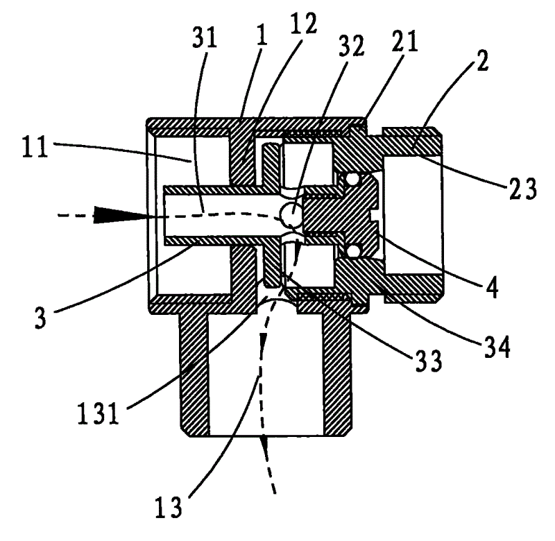
An automatic switching valve, comprising a three-way valve body and a spool in the movable and fixed valve body, the middle and front parts of the spool respectively form a large piston surface and a small piston surface; wherein the spool is a pipe with a shaft hole There is an outlet hole communicating with the shaft hole on the pipe wall between the large piston surface and the small piston surface, and a joint is fixed at the front of the valve body, the fixed head passes through the joint and is fixed with the valve core, and the valve core The small piston surface is movable and fits tightly with the joint. The water flow can flow in from the shaft hole and flow into the inner cavity of the valve body from the water outlet on the valve core. The valve body uses its side port to connect the water supply pipe, and the other port and the lower port are used as the water outlet to connect the water outlet device, and enter the valve body from the water outlet. The water in the cavity forms the water pressure on the two piston surfaces, so that the valve core moves back and forth to control the water outlets of the two water outlets respectively, so as to achieve the function of switching valve. Integrated design, and effectively reduce its installation space.
Description
技术领域 technical field
本实用新型涉及一种水路切换开关,特别是指一种自动切换阀。The utility model relates to a waterway switching switch, in particular to an automatic switching valve.
背景技术 Background technique
切换阀是目前卫浴系统中常用的开关装置,现在家居或是酒店中的淋浴喷头多是设有固定式的顶喷花洒与可移动的活动花洒以方便人们淋浴时的灵活选择。而两种出水花洒都是由一个出水管利用切换阀实现两条水路的选择出水。The switching valve is a commonly used switching device in the current bathroom system. Now most of the shower heads in homes or hotels are equipped with fixed overhead showers and movable movable showers to facilitate people's flexible choices when showering. The two kinds of water outlet showers all use a switching valve to realize the selection of two water channels by a water outlet pipe.
如图1、2所示,传统自动切换阀主要包括一阀体1’及一阀芯2’,该阀体1’的两端为出水口11’、12’以分别连接顶喷花洒管及活动花洒软管,阀体1’的阀腔13’为一阶梯孔,阀体1’的中部侧壁上设有与阀腔13’相通的进水孔14’;阀芯2’上设有两大小不同的活塞面21’、22’,两活塞面21’、22’分别套置密封圈置于阀腔13’中,并位于进水孔14’的两侧。配合图1所示,当大活塞面21’一端的出水口11’连接的出水装置开关是处于打开时,该阀芯2’即会受水压作用向大活塞面21’方向的出水口11’移动,令大活塞面21’移至阶梯孔的非密封位置,此端出水口11’与进水孔14’相通而出水,与此同时,另一小活塞面22’则会封堵另一端出水口12’方向的阶梯孔;配合图2所示,当大活塞面21’一端出水口11’连接的出水装置的开关关闭时,受水压作用,阀芯2’是向小活塞面22’方向的出水口12’移动,令小活塞面22’移至阶梯孔的非密封位置,此端出水口12’与进水孔14’相通而出水,与此同时,另一大活塞面21’则会封堵阶梯孔,其控制端的出水口11’不通,以此实现自动切换阀的功能。通常是大活塞面21’方向一端出水口11’连接的出水装置为活动花洒,而另一端出水口12’是连接顶喷花洒,因为操作活动花洒的开关较为方便,故仅依靠活动花洒上开关的开闭即可实现两个出水装置的选择出水。As shown in Figures 1 and 2, the traditional automatic switching valve mainly includes a valve body 1' and a valve core 2', and the two ends of the valve body 1' are water outlets 11' and 12' to connect to the overhead shower pipe respectively And the movable shower hose, the valve cavity 13' of the valve body 1' is a stepped hole, and the middle side wall of the valve body 1' is provided with a water inlet hole 14' communicating with the valve cavity 13'; There are two piston surfaces 21', 22' of different sizes. The two piston surfaces 21', 22' are respectively sleeved with sealing rings and placed in the valve chamber 13', and are located on both sides of the water inlet hole 14'. As shown in Figure 1, when the switch of the water outlet device connected to the water outlet 11' at the end of the large piston surface 21' is turned on, the valve core 2' will be subjected to water pressure to the
详观上述传统结构的自动切换阀,其进水孔14’是设在阀体1’的中部,而实际供水系统的出水管都是设在墙壁上,因此,该自动切换阀在安装于出水管上时,两出水口11’、12’是分别朝上、下两个方向,如此在连接顶喷花洒时,需要再在朝上方向的出水口12’处再设置弯管以适配顶喷花洒的出水方向,此势必造成自动切换阀安装空间的增加;并且阀体1’的长度为配合两个活塞面21’、22’的移动空间,其体积亦需设置较大方可满足功能需求。Looking at the automatic switching valve of the above-mentioned traditional structure in detail, the water inlet 14' is located in the middle of the valve body 1', and the outlet pipes of the actual water supply system are all located on the wall. Therefore, the automatic switching valve is installed on the outlet. When the water pipe is on the top, the two water outlets 11' and 12' are facing upward and downward respectively. In this way, when connecting the overhead shower, it is necessary to install an elbow at the upward water outlet 12' to adapt The water outlet direction of the top spray will inevitably increase the installation space of the automatic switching valve; and the length of the valve body 1' is to match the moving space of the two piston surfaces 21' and 22', and its volume must be set larger to meet Functional Requirements.
实用新型内容Utility model content
本实用新型的目的是提供一种空间占用少且与管路可一体化配合的自动切换阀。The purpose of the utility model is to provide an automatic switching valve which occupies less space and can be integrated with pipelines.
为实现上述目的,本实用新型的解决方案是:一种自动切换阀,包括一三通阀体及活动固定阀体中的阀芯,该阀芯的中部及前部分别形成大活塞面与小活塞面;其中该阀芯为具有轴孔的管体,在大活塞面与小活塞面之间的管壁上设有与轴孔相通的出口孔,而阀体的前部固定一接头,固定头穿过接头与阀芯固定在一起,阀芯的小活塞面活动的与接头密封配合。In order to achieve the above object, the solution of the utility model is: an automatic switching valve, including a three-way valve body and a spool in the movable fixed valve body, the middle and front of the spool form a large piston surface and a small piston respectively. Piston surface; wherein the valve core is a pipe body with a shaft hole, an outlet hole communicating with the shaft hole is provided on the pipe wall between the large piston surface and the small piston surface, and a joint is fixed at the front of the valve body to fix The head passes through the joint and is fixed together with the spool, and the small piston surface of the spool is movably matched with the joint for sealing.
所述阀体横向内腔中部形成一缩颈凸环,缩颈凸环中心为阀芯穿过的配合孔,该缩颈凸环前方设有与纵向内腔相通的通孔。A necking protruding ring is formed in the middle of the transverse inner chamber of the valve body, and the center of the necking protruding ring is a matching hole through which the valve core passes.
所述阀体的横向内腔的前后部分别设有配合内螺纹。The front and rear parts of the transverse inner cavity of the valve body are respectively provided with matching internal threads.
所述接头中部外缘形成限制接头螺入阀体深度的定位凸台,而接头内腔形成有三段阶梯孔,其中段为缩颈孔,前后两段为大于缩颈孔的扩孔。The outer edge of the middle part of the joint forms a positioning boss that limits the depth of the joint screwing into the valve body, and the inner cavity of the joint is formed with three sections of stepped holes, the middle section of which is a necking hole, and the front and rear sections are reaming holes that are larger than the necking hole.
所述接头的前后部分别设有配合外螺纹。The front and rear parts of the joint are respectively provided with matching external threads.
所述阀芯外径是小于等于阀体缩颈凸环的配合孔及接头的缩颈孔内径,在阀芯近中部的外缘延伸有大活塞面,该大活塞面的外径小于等于接头的后段扩孔内径,而大于接头中段的缩颈孔内径。The outer diameter of the valve core is less than or equal to the inner diameter of the matching hole of the valve body necking protrusion ring and the necking hole of the joint, and a large piston surface extends on the outer edge of the valve core near the middle, and the outer diameter of the large piston surface is less than or equal to that of the joint. The inner diameter of the expansion hole in the rear section of the joint is larger than the inner diameter of the necking hole in the middle section of the joint.
所述阀芯上的出水口设置为至少一个。There is at least one water outlet on the valve core.
所述固定头为一“T”形螺纹头,其后部设有配合内螺纹,并与阀芯前端的轴孔配合,而前部形成外径小于等于接头缩颈孔内径的端头。The fixed head is a "T"-shaped threaded head, and its rear part is provided with a matching internal thread, which is matched with the shaft hole at the front end of the valve core, while the front part forms a terminal with an outer diameter smaller than or equal to the inner diameter of the joint necking hole.
所述固定头与阀芯固定后与接头缩颈孔活动密封配合。After the fixed head is fixed with the valve core, it is movable and sealed with the constriction hole of the joint.
采用上述方案后,本实用新型的自动切换阀,在三通的阀体中设有的阀芯具有轴孔,水流可从轴孔流入并从阀芯上的出水口流入阀体内腔中,阀体可以利用其侧面端口连接供水管,而另一端口及下部的端口作为出水口连接出水装置,阀芯的大小活塞面是分别设在出水口的前后侧,从出水口进入阀体内腔形成对两活塞面产生水压力,以令阀芯前后移动而控制两出水口分别出水,达到切换阀的功能,因阀芯利用接头及固定头进行固定,而该接头是直接外接管体的配件,因此该自动切换阀可与管路实现一体化设计,并有效缩小其安装的空间。After adopting the above scheme, in the automatic switching valve of the present utility model, the valve core provided in the three-way valve body has a shaft hole, and the water flow can flow in from the shaft hole and flow into the inner cavity of the valve body from the water outlet on the valve core. The body can use its side port to connect the water supply pipe, while the other port and the lower port are used as the water outlet to connect the water outlet device. The two piston surfaces generate water pressure to make the valve core move back and forth to control the water outlets of the two water outlets to achieve the function of switching valves. Because the valve core is fixed by the joint and the fixed head, and the joint is a direct external fitting of the pipe body, so The automatic switching valve can be integrated with the pipeline, and the installation space can be effectively reduced.
附图说明 Description of drawings
图1是传统自动切换阀的结构剖视图1;Fig. 1 is a structural
图2是传统自动切换阀的结构剖视图2;Fig. 2 is a structural
图3是本实用新型的实施示意图;Fig. 3 is the implementation schematic diagram of the utility model;
图4是本实用新型的结构剖视图;Fig. 4 is a structural sectional view of the utility model;
图5是本实用新型阀芯的立体示意图;Fig. 5 is a three-dimensional schematic diagram of a valve core of the present invention;
图6是本实用新型的工作示意图(进水初始状态);Fig. 6 is a working schematic diagram of the utility model (initial state of water intake);
图7是本实用新型的工作示意图(移动花洒出水状态);Fig. 7 is a working schematic diagram of the utility model (the water outlet state of the mobile shower);
图8是本实用新型的工作示意图(顶喷花洒出水状态)。Fig. 8 is a working schematic diagram of the utility model (the state of spraying water from the top sprayer).
具体实施方式 Detailed ways
如图4并配合图3所示,本实用新型的自动切换阀,其包括一阀体1、一接头2、一阀芯3及一固定头4。As shown in FIG. 4 and FIG. 3 , the automatic switching valve of the present invention includes a
阀体1为一三通管,其横向内腔11中部形成一缩颈凸环12,缩颈凸环12中心为配合孔121,该缩颈凸环12前方设有与纵向内腔13相通的通孔131,该阀体1的横向内腔11的前后部分别设有配合内螺纹。The
接头2的前后部分别设有配合外螺纹,其中部外缘形成定位凸台21,以限制接头2螺入阀体1中的深度,而接头2内腔形成有三段阶梯孔,其中段为缩颈孔22,前后两段为大于缩颈孔的扩孔23;在接头2的前后分别设有配合外螺纹,以令接头2的一端是旋入阀体1中,另一端与外接的管路连接以实现接头的作用。The front and rear parts of the
配合图5所示,阀芯3为一具轴孔31的管体,其外径是小于等于上述缩颈凸环12的配合孔121及上述接头2的缩颈孔内径,在管体近中部的外缘延伸有大活塞面33,该大活塞面33的外径小于等于上述接头2的后段扩孔内径,而大于接头2中段的缩颈孔22内径;在大活塞面33前方的管壁上设有与轴孔31相通的出水口32,该出水口32可以设置为多个,如四个;在阀芯3前部设有配合内螺纹,而阀芯3的前端设有小活塞面34。As shown in Figure 5, the
固定头4为一“T”形螺纹头,其后部设有配合内螺纹,并与阀芯3的轴孔31配合,而前部形成外径小于等于接头2缩颈孔22内径的端头。The
如图4所示,该切换阀在组合时,阀芯3自阀体2前方置入横向内腔11中,阀芯3的后部管体从缩颈凸环12中心的配合孔121伸置于横向内腔11的后部,接头2的后部螺接于横向内腔11前部,二者形成密封配合;固定头4自接头2的通孔螺锁于阀芯3前部,同时固定头4的端头与阀芯3前端的小活塞面34之间形成设置密封圈的空间,则阀芯3前端套置密封圈并连接固定头4后,与接头2的缩颈孔22之间形成密封配合,如图4所示,当阀芯3的大活塞面33抵靠在缩颈凸环12的前端面时,固定头4是处于接头2的缩颈孔22中以形成一自动切换阀。As shown in Figure 4, when the switching valve is combined, the
配合图3所示,该自动切换阀在组装于卫浴间时,阀体1横向内腔11后部即可直接连接供水管,而前部利用接头2直接连接顶喷花洒A,纵向内腔13下部直接与移动花洒B的连接软管B1连接在一起。其完全可以因应顶喷花洒A与移动花洒B的安装位置而设置,并且阀体1前端与接头2的配合,令此自动切换阀可与管路实现一体设计,有效缩小了其安装的空间。As shown in Fig. 3, when the automatic switching valve is assembled in the bathroom, the rear part of the
当该自动切换阀工作时,打开水源开关,由移动花洒B的通断而控制顶喷花洒A断通,移动花洒B出水时,顶喷花洒A是关闭的;而移动花洒B关闭时,顶喷花洒A是出水状态。When the automatic switching valve is working, turn on the water source switch, and the on-off of the mobile shower B will control the on-off of the top-spray shower A. When the mobile shower B emits water, the top-spray shower A is closed; When B is turned off, the top spray A is in the water outlet state.
如图6所示,打开水源开关,水流自阀体1流入阀芯3的轴孔31,并从出水口32流进阀体1前部与接头2形成的空间中,此时阀芯3的大活塞面33与小活塞面34都受到了水压力,由于大活塞面33的面积大于小活塞面34,阀芯3会相阀1向后移动(配合图7所示),固定头4是与接头2的缩颈孔22密封配合,因此,顶喷花洒A是处于关闭状态,而水流会从阀体1纵向内腔13流入移动花洒B,此时的移动花洒B是打开出水状态。As shown in Figure 6, turn on the water source switch, the water flows from the
如图8所示,当关闭移动花洒B的出水开关,则阀体1下部的纵向内腔13是处于关闭状态,此时由于下部区域没有水流,阀芯3大活塞面33的左右两侧压力相互抵消,而大活塞面33受到向前的压力,阀芯3向前移动,待大活塞面33前端面抵靠在接头2缩颈孔22的后端面上时,阀芯3的出水孔32是伸置在缩颈孔22处,与此同时小活塞面34与固定头4是伸出于缩颈孔22之外,此时接头2是为打开状态,此时的水流是流入顶喷花洒A中,顶喷花洒A处于出水状态。As shown in Figure 8, when the water outlet switch of the mobile shower B is turned off, the longitudinal
综上,本实用新型的自动切换阀,在三通的阀体1中设有的阀芯3具有轴孔31,水流可从轴孔31流入并从阀芯3上的出水口32流入阀体1内腔中,则阀体1可以利用其侧面端口连接供水管,而另一端口及下部的端口作为出水口连接出水装置,阀芯3的大小活塞面33、34是分别设在出水口32的前后侧,从出水口32进入阀体1内腔形成对两活塞面33、34产生压力,以令阀芯3前后移动而控制两出水口分别出水,达到切换阀的功能,因阀芯3利用接头2及固定头4进行固定,而该接头2是直接外接管体的配件,因此该自动切换阀可与管路实现一体化设计,并有效缩小其安装的空间。To sum up, in the automatic switching valve of the present utility model, the
Claims (9)
Priority Applications (1)
| Application Number | Priority Date | Filing Date | Title |
|---|---|---|---|
| CNU200820229263XU CN201326776Y (en) | 2008-12-01 | 2008-12-01 | Automatic switching valve |
Applications Claiming Priority (1)
| Application Number | Priority Date | Filing Date | Title |
|---|---|---|---|
| CNU200820229263XU CN201326776Y (en) | 2008-12-01 | 2008-12-01 | Automatic switching valve |
Publications (1)
| Publication Number | Publication Date |
|---|---|
| CN201326776Y true CN201326776Y (en) | 2009-10-14 |
Family
ID=41178749
Family Applications (1)
| Application Number | Title | Priority Date | Filing Date |
|---|---|---|---|
| CNU200820229263XU Expired - Fee Related CN201326776Y (en) | 2008-12-01 | 2008-12-01 | Automatic switching valve |
Country Status (1)
| Country | Link |
|---|---|
| CN (1) | CN201326776Y (en) |
Cited By (11)
| Publication number | Priority date | Publication date | Assignee | Title |
|---|---|---|---|---|
| WO2012025028A1 (en) * | 2010-08-23 | 2012-03-01 | 厦门松霖科技有限公司 | Slide switching water outlet mechanism |
| CN105757273A (en) * | 2016-05-05 | 2016-07-13 | 梁旭 | Water-saving shower set |
| CN106400923A (en) * | 2016-06-25 | 2017-02-15 | 中山市美图塑料工业有限公司 | A toilet structure with deodorizing function |
| EP3147029A3 (en) * | 2015-09-25 | 2017-08-02 | Hongxin Lin | Inductive showerhead and multi-waterway switching mechanism |
| CN107314125A (en) * | 2017-07-14 | 2017-11-03 | 浙江华益精密机械股份有限公司 | Step type three-way switching valve |
| CN107814421A (en) * | 2017-12-10 | 2018-03-20 | 泰兴市洁源环保工程有限公司 | A kind of water-locator for water process |
| CN107842632A (en) * | 2017-12-05 | 2018-03-27 | 厦门三骏工贸有限公司 | A kind of double Lode switching valves |
| CN108087365A (en) * | 2017-12-19 | 2018-05-29 | 宁波文泽机电技术开发有限公司 | Oil circuit automatic transfer valve |
| CN110285068A (en) * | 2019-06-28 | 2019-09-27 | 辛贵颜 | A kind of water pump |
| CN112502245A (en) * | 2020-12-08 | 2021-03-16 | 厦门大白科技有限公司 | Induction gargling tap |
| CN113154085A (en) * | 2021-04-23 | 2021-07-23 | 福建科迪厨卫有限公司 | Automatic switching three way connection |
-
2008
- 2008-12-01 CN CNU200820229263XU patent/CN201326776Y/en not_active Expired - Fee Related
Cited By (15)
| Publication number | Priority date | Publication date | Assignee | Title |
|---|---|---|---|---|
| US8919380B2 (en) | 2010-08-23 | 2014-12-30 | Xiamen Solex High-Tech Industries Co., Ltd. | Sliding switch outlet mechanism |
| WO2012025028A1 (en) * | 2010-08-23 | 2012-03-01 | 厦门松霖科技有限公司 | Slide switching water outlet mechanism |
| EP3147029A3 (en) * | 2015-09-25 | 2017-08-02 | Hongxin Lin | Inductive showerhead and multi-waterway switching mechanism |
| CN105757273A (en) * | 2016-05-05 | 2016-07-13 | 梁旭 | Water-saving shower set |
| CN106400923B (en) * | 2016-06-25 | 2019-08-06 | 中山市美图塑料工业有限公司 | Toilet structure with deodorization function |
| CN106400923A (en) * | 2016-06-25 | 2017-02-15 | 中山市美图塑料工业有限公司 | A toilet structure with deodorizing function |
| CN107314125A (en) * | 2017-07-14 | 2017-11-03 | 浙江华益精密机械股份有限公司 | Step type three-way switching valve |
| CN107314125B (en) * | 2017-07-14 | 2023-12-22 | 浙江华益精密机械有限公司 | Step type three-way switching valve |
| CN107842632A (en) * | 2017-12-05 | 2018-03-27 | 厦门三骏工贸有限公司 | A kind of double Lode switching valves |
| CN107842632B (en) * | 2017-12-05 | 2024-05-10 | 厦门三骏工贸有限公司 | Double-waterway switching valve |
| CN107814421A (en) * | 2017-12-10 | 2018-03-20 | 泰兴市洁源环保工程有限公司 | A kind of water-locator for water process |
| CN108087365A (en) * | 2017-12-19 | 2018-05-29 | 宁波文泽机电技术开发有限公司 | Oil circuit automatic transfer valve |
| CN110285068A (en) * | 2019-06-28 | 2019-09-27 | 辛贵颜 | A kind of water pump |
| CN112502245A (en) * | 2020-12-08 | 2021-03-16 | 厦门大白科技有限公司 | Induction gargling tap |
| CN113154085A (en) * | 2021-04-23 | 2021-07-23 | 福建科迪厨卫有限公司 | Automatic switching three way connection |
Similar Documents
| Publication | Publication Date | Title |
|---|---|---|
| US10047505B2 (en) | Cool water draining switch valve and combination shower head | |
| CN201802912U (en) | Water changeover valve structure | |
| US20100181519A1 (en) | Automatic switch valve | |
| CN203730777U (en) | Press type valve body structure and bidet using valve body | |
| CN221972579U (en) | A magnetic water-passing structure for a shower head | |
| CN217630270U (en) | Water swivel and foaming device | |
| CN204093602U (en) | A kind of urinal nozzle | |
| CN205462804U (en) | An anti-drip shower head | |
| CN205599366U (en) | Adjustable gondola water faucet of flow | |
| CN212975528U (en) | Hand-held shower | |
| CN210423874U (en) | Water outlet device capable of being stopped immediately after being closed, faucet and shower | |
| CN206996891U (en) | One kind automatically resets waterway regulating valve and the Flow-rate adjustment gondola water faucet that automatically resets | |
| CN201303896Y (en) | Assembly structure of shower and top shower | |
| CN201715036U (en) | Automatic water distributor for showering | |
| CN113499868B (en) | Shower device | |
| CN116624621B (en) | A double switch spray gun socket faucet | |
| KR101989175B1 (en) | An adapter for branching pipe | |
| CA2485484A1 (en) | Bathtub water tap | |
| JP3148258U (en) | Hot water mixing faucet device for double structure shower head | |
| CN223805642U (en) | A pressure boosting device for toilet inlet pipes | |
| CN219639619U (en) | A concealed button valve | |
| CN105457774A (en) | An anti-drip shower head | |
| CN205907764U (en) | Universal shower head | |
| CN223331190U (en) | Faucet with spray gun | |
| CN219549724U (en) | High-sealing flushing valve with adjustable installation length |
Legal Events
| Date | Code | Title | Description |
|---|---|---|---|
| C14 | Grant of patent or utility model | ||
| GR01 | Patent grant | ||
| C17 | Cessation of patent right | ||
| CF01 | Termination of patent right due to non-payment of annual fee |
Granted publication date: 20091014 Termination date: 20121201 |