CN201321497Y - Multifunctional online testing device for electrobath - Google Patents
Multifunctional online testing device for electrobath Download PDFInfo
- Publication number
- CN201321497Y CN201321497Y CNU2008202310977U CN200820231097U CN201321497Y CN 201321497 Y CN201321497 Y CN 201321497Y CN U2008202310977 U CNU2008202310977 U CN U2008202310977U CN 200820231097 U CN200820231097 U CN 200820231097U CN 201321497 Y CN201321497 Y CN 201321497Y
- Authority
- CN
- China
- Prior art keywords
- acquisition module
- analog conversion
- casing
- computer
- digital
- Prior art date
- Legal status (The legal status is an assumption and is not a legal conclusion. Google has not performed a legal analysis and makes no representation as to the accuracy of the status listed.)
- Expired - Fee Related
Links
- 238000012360 testing method Methods 0.000 title claims abstract description 14
- 238000005070 sampling Methods 0.000 claims abstract description 19
- 238000006243 chemical reaction Methods 0.000 claims abstract description 16
- 238000005259 measurement Methods 0.000 description 4
- 238000009434 installation Methods 0.000 description 3
- 238000010586 diagram Methods 0.000 description 2
- 238000012545 processing Methods 0.000 description 2
- PNEYBMLMFCGWSK-UHFFFAOYSA-N aluminium oxide Inorganic materials [O-2].[O-2].[O-2].[Al+3].[Al+3] PNEYBMLMFCGWSK-UHFFFAOYSA-N 0.000 description 1
- 238000009529 body temperature measurement Methods 0.000 description 1
- 230000007812 deficiency Effects 0.000 description 1
- 239000003792 electrolyte Substances 0.000 description 1
- 238000000034 method Methods 0.000 description 1
- 238000012544 monitoring process Methods 0.000 description 1
Images


Classifications
-
- Y—GENERAL TAGGING OF NEW TECHNOLOGICAL DEVELOPMENTS; GENERAL TAGGING OF CROSS-SECTIONAL TECHNOLOGIES SPANNING OVER SEVERAL SECTIONS OF THE IPC; TECHNICAL SUBJECTS COVERED BY FORMER USPC CROSS-REFERENCE ART COLLECTIONS [XRACs] AND DIGESTS
- Y02—TECHNOLOGIES OR APPLICATIONS FOR MITIGATION OR ADAPTATION AGAINST CLIMATE CHANGE
- Y02P—CLIMATE CHANGE MITIGATION TECHNOLOGIES IN THE PRODUCTION OR PROCESSING OF GOODS
- Y02P10/00—Technologies related to metal processing
- Y02P10/20—Recycling
Landscapes
- Electrolytic Production Of Non-Metals, Compounds, Apparatuses Therefor (AREA)
Abstract
本实用新型公开了一种电解槽多功能在线测试装置,计算机镶嵌在机壳内上部,电源指示灯、运行指示灯、电源开关装置在前门面上,温度采集模块、阳极电流采集模块、电压采集模块、数模转换模块固定安装在机壳内部,取样卡放置在机壳的后部空间,温度采集模块、阳极电流采集模块、电压采集模块的输入端分别连接有取样卡,输出端分别与数模转换模块输入端相连接,数模转换模块的输出端连接到计算机,计算机上输出端可以实时显示阳极电流分布、电解槽电压、电解槽温度等数据,并且能绘制出电流、电压、温度曲线。方便管理人员及时了解电解槽状况,为控制电解槽提供及时准确的数据。
The utility model discloses a multifunctional on-line testing device for an electrolytic cell. A computer is embedded in the upper part of a casing, a power indicator light, an operation indicator light, and a power switch device are on the front door, and a temperature acquisition module, an anode current acquisition module, and a voltage acquisition module The module and the digital-to-analog conversion module are fixedly installed inside the casing, and the sampling card is placed in the rear space of the casing. The input ends of the analog conversion module are connected, and the output end of the digital-analog conversion module is connected to the computer. The output end of the computer can display the anode current distribution, electrolytic cell voltage, electrolytic cell temperature and other data in real time, and can draw current, voltage, and temperature curves. . It is convenient for managers to keep abreast of the status of the electrolyzer and provide timely and accurate data for controlling the electrolyzer.
Description
技术领域: Technical field:
本实用新型属于氧化铝电解槽工作参数在线测试技术领域。The utility model belongs to the technical field of on-line testing of working parameters of an alumina electrolytic cell.
背景技术: Background technique:
目前公知的电解槽在线测试装置,是由阳极电流取样模块、导线、数模转换、计算机等构成的阳极电流分布测试装置,只对阳极电流分布进行测试。在线测试装置在现场看不到实时状态,也做不到多数据测试,无法对电解槽进行多项工作参数进行分析。Currently known on-line testing devices for electrolyzers are anode current distribution testing devices composed of anode current sampling modules, wires, digital-to-analog converters, computers, etc., and only test anode current distribution. The online testing device cannot see the real-time status at the site, nor can it perform multi-data testing, and cannot analyze multiple working parameters of the electrolytic cell.
实用新型内容: Utility model content:
为了克服现有的在线测试装置不能多数据测试和现场实时监控的不足,本实用新型提供一种电解槽多功能在线测试装置,该装置不仅能同时测出多个阳极电流分布值、多点电解质温度、槽电压,而且能方便在现场看出分布图形、电压曲线以及温度的变化等。In order to overcome the deficiency that the existing on-line testing device cannot perform multi-data testing and on-site real-time monitoring, the utility model provides a multifunctional on-line testing device for an electrolytic cell, which can not only measure multiple anode current distribution values, multi-point electrolyte Temperature, tank voltage, and can easily see the distribution graph, voltage curve and temperature changes on site.
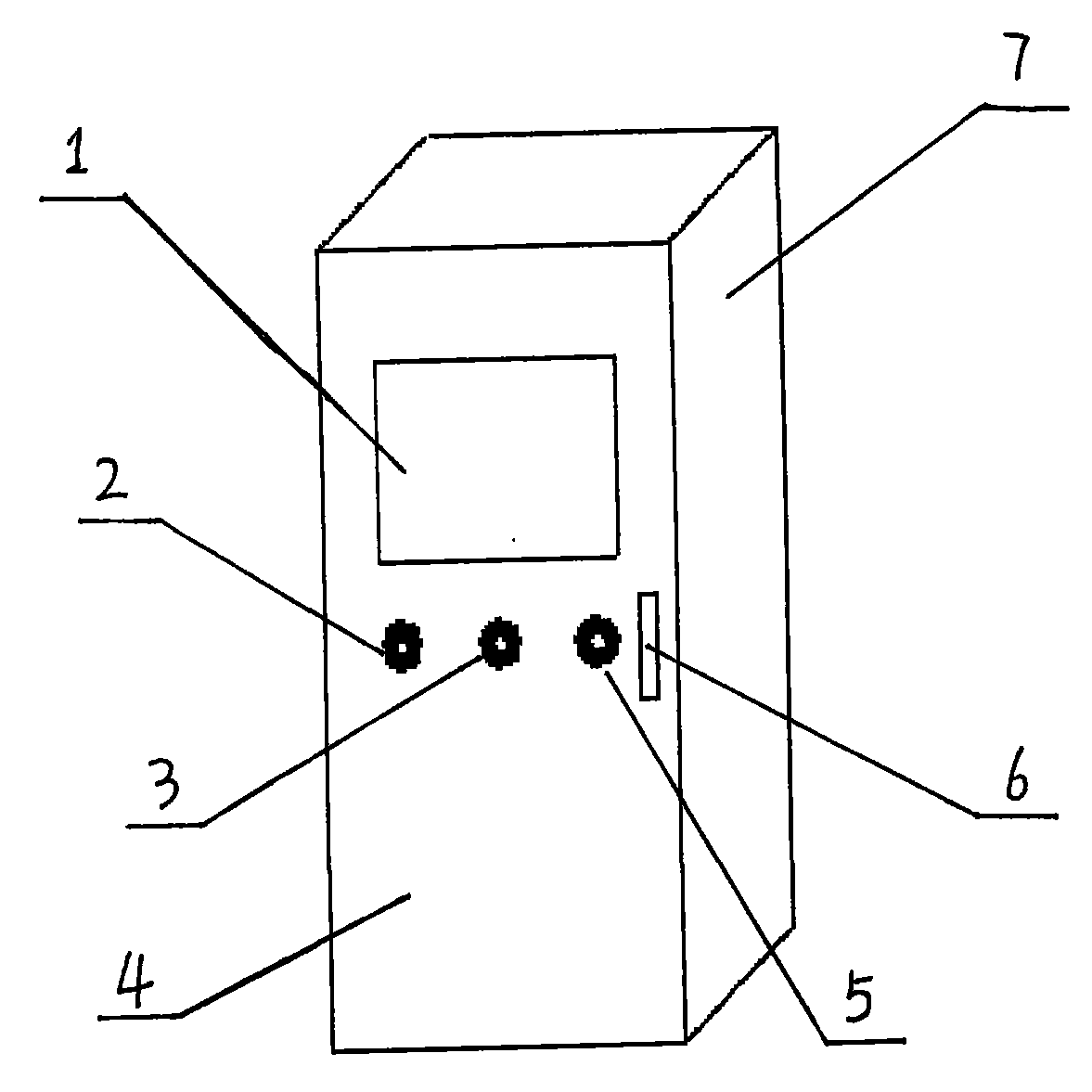
为了实现上述目的,本实用新型包括:计算机、电源指示灯、运行指示灯、前门面、电源开关、前门把手、机壳、温度采集模块、阳极电流采集模块、电压采集模块、数模转换模块、取样卡,计算机镶嵌在机壳内上部,电源指示灯、运行指示灯、电源开关装置在前门面上,温度采集模块、阳极电流采集模块、电压采集模块、数模转换模块固定安装在机壳内部,取样卡放置在机壳的后部空间,温度采集模块、阳极电流采集模块、电压采集模块的输入端分别连接有取样卡,输出端分别与数模转换模块输入端相连接,数模转换模块的输出端连接到计算机。In order to achieve the above object, the utility model includes: a computer, a power indicator light, a running indicator light, a front facade, a power switch, a front door handle, a casing, a temperature acquisition module, an anode current acquisition module, a voltage acquisition module, a digital-to-analog conversion module, The sampling card, the computer is embedded in the upper part of the casing, the power indicator light, the operation indicator light, and the power switch device are on the front door, and the temperature acquisition module, anode current acquisition module, voltage acquisition module, and digital-to-analog conversion module are fixedly installed inside the enclosure , the sampling card is placed in the rear space of the casing, the input ends of the temperature acquisition module, the anode current acquisition module, and the voltage acquisition module are respectively connected to the sampling card, and the output ends are respectively connected to the input ends of the digital-to-analog conversion module, and the digital-to-analog conversion module The output terminal is connected to the computer.
这样,测量作业时,确定要测量的电解槽后,将电解多功能测量装置推到电解槽旁边,打开槽盖板,取出取样卡,一个人在测量区,依照取样卡的编号,依次将阳极电流取样卡安装在相应的阳极上,把测量温度的取样卡和电压的取样卡安装在需要测试的位置,另一个人进行操作装置运行情况,并通过输出软件系统记录数据,测试完毕后,由测量人员收回快速取样卡、多芯电缆,盖上槽盖板,把数据送到计算机中进行解析处理,然后测试下一台电解槽。本实用新型由计算机作为控制中心,计算机上输出端可以实时显示阳极电流分布、电解槽电压、电解槽温度等数据,并且能绘制出电流、电压、温度曲线。可以方便管理人员及时了解电解槽状况,为控制电解槽提供及时准确的数据,保证电解槽技术条件稳定。In this way, during the measurement operation, after determining the electrolytic cell to be measured, push the electrolytic multifunctional measuring device to the side of the electrolytic cell, open the cell cover, take out the sampling card, and one person in the measurement area, according to the number of the sampling card, sequentially place the anode Install the current sampling card on the corresponding anode, install the sampling card for temperature measurement and the sampling card for voltage at the position to be tested, another person will operate the operation of the device, and record the data through the output software system. After the test is completed, by The measurement personnel take back the quick sampling card and multi-core cable, cover the tank cover, send the data to the computer for analysis and processing, and then test the next electrolyzer. The utility model uses a computer as the control center, and the output terminal on the computer can display data such as anode current distribution, electrolytic cell voltage, and electrolytic cell temperature in real time, and can draw current, voltage, and temperature curves. It is convenient for management personnel to know the status of the electrolyzer in time, provide timely and accurate data for controlling the electrolyzer, and ensure the stability of the technical condition of the electrolyzer.
附图说明: Description of drawings:
下面结合附图对本实用新型作进一步详细说明。Below in conjunction with accompanying drawing, the utility model is described in further detail.
图1为本实用新型的外部结构示意图。Fig. 1 is a schematic diagram of the external structure of the utility model.
图2为本实用新型的电气原理方框图。Fig. 2 is the electrical principle block diagram of the utility model.
具体实施方式: Detailed ways:
由图1、图2可知,本实用新型包括:计算机1、电源指示灯2、运行指示灯3、前门面4、电源开关5、前门把手6、机壳7、温度采集模块、阳极电流采集模块、电压采集模块、数模转换模块、取样卡,计算机1镶嵌在机壳7内上部,电源指示灯2、运行指示灯3、电源开关5装置在前门面4上,温度采集模块、阳极电流采集模块、电压采集模块、数模转换模块固定安装在机壳内部,安装部件分层分布,同一层内有一个或多个部件安装体,接线端子安装在机壳的下方,这样有利于内部合理和方便布线,避免对部件的安装造成不必要的麻烦,连接导线从接线端子由下至上连接至所要连接的用电部件上。取样卡放置在机壳的后部空间,温度采集模块、阳极电流采集模块、电压采集模块的输入端分别连接取样卡,输出端分别与数模转换模块输入端相连接。利用各个取样卡分别从电解槽采集数据,采集到的数据通过多芯电缆把信号传输到数模转换模块,数模转换模块的输出端连接到计算机,然后由计算机上的输出软件系统对数据进行处理。机壳分前后两部分,机壳后面有大量空间,多芯电缆、快速取样卡等工具可以放置在机壳的后面。机壳本身是移动式的,底部装有滚轮,可以方便在现场对一个一个的电解槽进行测量,即可以提高工作效率,又可以节约人力。As can be seen from Fig. 1 and Fig. 2, the utility model includes: a
Claims (1)
Priority Applications (1)
| Application Number | Priority Date | Filing Date | Title |
|---|---|---|---|
| CNU2008202310977U CN201321497Y (en) | 2008-12-24 | 2008-12-24 | Multifunctional online testing device for electrobath |
Applications Claiming Priority (1)
| Application Number | Priority Date | Filing Date | Title |
|---|---|---|---|
| CNU2008202310977U CN201321497Y (en) | 2008-12-24 | 2008-12-24 | Multifunctional online testing device for electrobath |
Publications (1)
| Publication Number | Publication Date |
|---|---|
| CN201321497Y true CN201321497Y (en) | 2009-10-07 |
Family
ID=41158883
Family Applications (1)
| Application Number | Title | Priority Date | Filing Date |
|---|---|---|---|
| CNU2008202310977U Expired - Fee Related CN201321497Y (en) | 2008-12-24 | 2008-12-24 | Multifunctional online testing device for electrobath |
Country Status (1)
| Country | Link |
|---|---|
| CN (1) | CN201321497Y (en) |
Cited By (3)
| Publication number | Priority date | Publication date | Assignee | Title |
|---|---|---|---|---|
| CN105926005A (en) * | 2016-06-16 | 2016-09-07 | 迟晓莉 | Direct current power system for extracting muscone and control method thereof |
| CN113881953A (en) * | 2021-11-09 | 2022-01-04 | 江苏安凯特科技股份有限公司 | Intelligent on-line monitoring unit and intelligent control method |
| CN114369849A (en) * | 2022-01-04 | 2022-04-19 | 阳光氢能科技有限公司 | A method and device for monitoring the health of an electrolytic cell, and an electrolytic cell monitoring system |
-
2008
- 2008-12-24 CN CNU2008202310977U patent/CN201321497Y/en not_active Expired - Fee Related
Cited By (5)
| Publication number | Priority date | Publication date | Assignee | Title |
|---|---|---|---|---|
| CN105926005A (en) * | 2016-06-16 | 2016-09-07 | 迟晓莉 | Direct current power system for extracting muscone and control method thereof |
| CN105926005B (en) * | 2016-06-16 | 2017-03-15 | 迟晓莉 | A kind of DC power system for extracting muscone and its control method |
| CN113881953A (en) * | 2021-11-09 | 2022-01-04 | 江苏安凯特科技股份有限公司 | Intelligent on-line monitoring unit and intelligent control method |
| CN114369849A (en) * | 2022-01-04 | 2022-04-19 | 阳光氢能科技有限公司 | A method and device for monitoring the health of an electrolytic cell, and an electrolytic cell monitoring system |
| CN114369849B (en) * | 2022-01-04 | 2024-01-30 | 阳光氢能科技有限公司 | Method and device for monitoring health degree of electrolytic cell and electrolytic cell monitoring system |
Similar Documents
| Publication | Publication Date | Title |
|---|---|---|
| CN103108412A (en) | Remote monitoring system on parameters of aquafarm water quality and control method | |
| CN102305922A (en) | On-load detection method and device for intelligent optical fiber electric energy meter in substation | |
| CN105607027A (en) | High-low temperature weather effect testing device for electric energy meter | |
| CN202230195U (en) | On-load detection device for intelligent optical-fiber electric energy meter in transformer station | |
| CN102735975A (en) | Real-time energy efficiency tester of elevator group and testing method | |
| CN206807145U (en) | A kind of automatic test device of distribution terminal | |
| CN204177943U (en) | A kind of intelligent battery state verification instrument based on ARM embedded system | |
| CN202793450U (en) | Data monitoring and acquiring device for small photovoltaic power generation system | |
| CN105203151A (en) | Industrial Internet of Things comprehensive test instrument | |
| CN104155932A (en) | Distributed photovoltaic grid-connected power generation monitoring system, energy consumption managing method and photovoltaic grid-connected power generation monitoring equipment | |
| CN102560532A (en) | Detecting system for state of electrolytic cell | |
| CN219574355U (en) | A new online monitoring device for electric energy metering error | |
| CN205643657U (en) | Computer protection device with on -line monitoring switching power supply life -span | |
| CN203133201U (en) | Integrated measurement device for energy-storage grid-connected system | |
| CN209233491U (en) | A kind of photovoltaic plant management system of family grade | |
| CN203858290U (en) | Wireless sensor for measuring end-screen current of capacitive equipment | |
| CN203965921U (en) | The distributed photovoltaic supervisory system of generating electricity by way of merging two or more grid systems | |
| CN205301405U (en) | Novel digital power frequency virtual value multimeter of low -power consumption | |
| CN106124986A (en) | A kind of motor measurement apparatus | |
| CN206788159U (en) | A kind of submerging test sedimentation monitoring system based on hydrostatic level | |
| CN204927452U (en) | A collection module of lead-acid battery and a new type of lead-acid battery | |
| CN2854608Y (en) | Electric energy metering data monitor | |
| CN209265224U (en) | A kind of intelligent monitor | |
| CN211905531U (en) | Novel portable electric energy quality analyzer | |
| CN208432704U (en) | Multi-stroke battery voltage measuring instrument |
Legal Events
| Date | Code | Title | Description |
|---|---|---|---|
| C14 | Grant of patent or utility model | ||
| GR01 | Patent grant | ||
| C17 | Cessation of patent right | ||
| CF01 | Termination of patent right due to non-payment of annual fee |
Granted publication date: 20091007 Termination date: 20101224 |