CN201278423Y - Hub set - Google Patents
Hub set Download PDFInfo
- Publication number
- CN201278423Y CN201278423Y CNU2008201340829U CN200820134082U CN201278423Y CN 201278423 Y CN201278423 Y CN 201278423Y CN U2008201340829 U CNU2008201340829 U CN U2008201340829U CN 200820134082 U CN200820134082 U CN 200820134082U CN 201278423 Y CN201278423 Y CN 201278423Y
- Authority
- CN
- China
- Prior art keywords
- signal
- hub device
- main body
- plug
- attaching plug
- Prior art date
- Legal status (The legal status is an assumption and is not a legal conclusion. Google has not performed a legal analysis and makes no representation as to the accuracy of the status listed.)
- Expired - Fee Related
Links
Images


Abstract
The utility model provides a line concentrator device comprising a main body, a plurality of signal connecting ports, a signal plug group and an attaching plug group, wherein the main body is internally provided with a circuit board and a power conversion mechanism connected to the circuit board; the plurality of signal connecting ports are arranged in the main body and electrically connected to the circuit board; the signal plug group is arranged on the main body, is electrically connected to the power conversion mechanism and is provided with a signal plug; and the attaching plug groups is pivoted on the main body, is electrically connected to the power conservation mechanism and is provided with an attaching plug. By utilizing the power conservation mechanism to convert AC voltage or DC voltage into DC voltage and providing an external power supply to the signal connecting ports, the utility model can keep good and stable supplying power supply and can simultaneously charge and transmit signals.
Description
Technical field
The utility model relates to a kind of hub device, refer in particular to a kind of by electric transformational structure as power source conversion, and Signal plug group and attaching plug group arranged in pairs or groups in the hub device of electric transformational structure.
Background technology
Now, general serial formula bus (USB) applies in the information products widely, with the standard of the interface system that is connected with communication as transfer of data.Wherein, various peripheral electronic device can be utilized general serial formula bus (USB), by USB interface to be connected in computer equipment or the relevant information communication device.Therefore, only need peripheral electronic device be connected in the computer equipment by the utilization of single USB specification pattern.Simultaneously, general serial formula bus also has the characteristics of hot plug, when installing or removing various peripheral electronic device, does not also need other install driver.
In order to expand the function of use of general serial formula bus interface, there is a kind of scheme that a kind of USB line concentrator is provided at present, connect a plurality of USB interface to be integrated into this line concentrator by a usb host unit.Yet, above-mentioned USB line concentrator must rely on the connection computer equipment, power supply unit by computer equipment inside is kept running so that power supply to be provided, itself can't provide single power supply independently to operate, if it is too much to be connected in the electronic installation of USB line concentrator, undertension then often takes place, cause the difficulty in transfer of data, the storage, severe patient will cause computer equipment to load excessive and the situation of the machine of delaying.Simultaneously, the USB line concentrator also has the excessive and flimsy problem of load.
The utility model content
The purpose of this utility model provides a kind of hub device, be provided with an electric transformational structure in body interior, and utilize electric transformational structure that AC power or DC power supply are transformed into DC power supply, collocation Signal plug group and attaching plug group are electrically connected under the structural design of electric transformational structure, make that external power source can be via the electrical grafting of attaching plug group, for the signal connection end mouth provides good and stable power supply.Therefore, the user can be connected in outside supply socket by the attaching plug group according to different conditions of demand, and stable power source is provided.
Another purpose of the present utility model is, even under computer installation fault or not start situation, still can be by the attaching plug group, make this hub device be used as a cradle, and be the power source that various electronic installation supplies replenish, carry out the data between the electronic installation,, also can carry out data or charging respectively so can charge simultaneously and data.
To achieve the above object, the utility model provides a kind of hub device, comprising:
One main body, inside are provided with the electric transformational structure that a circuit board and is electrically connected on this circuit board;
A plurality of signal connection end mouths are located in this main body and are electrically connected on this circuit board;
One Signal plug group is located on this main body, and this Signal plug group is electrically connected on this electricity transformational structure, and this Signal plug group has a Signal plug; And
One attaching plug group is hubbed on this main body, and this attaching plug group is electrically connected on this electricity transformational structure, and this attaching plug group has an attaching plug.
Compared with prior art, the utlity model has following beneficial effect:
The utility model utilizes Signal plug group and attaching plug group to be electrically connected on electric transformational structure, make hub device that the stable external power source can be provided, the signal connection end mouth is good to keep, stable power, thereby has improved the stability of electronic installation running.
Utilize structure of the present utility model, even under the situation of computer installation fault or not start, still can be plugged in external power source, make hub device be used as a cradle by the attaching plug group, be various electronic installation power supplies, and provide the good data signal transmission quality for electronic installation.
When the electronic installation that is plugged in the signal connection end mouth more after a little while, user's can select to use a computer power supply of supply of equipment makes hub device provide power supply to electronic installation, carries out the data of electronic installation.
Use by attaching plug group and Signal plug group, can between different electronic installations, carry out data, and,, also can charge separately or data so both can charge simultaneously and data at the electronic installation action of charging.
Description of drawings
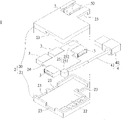
Fig. 1 is the body exploded view of the utility model hub device first embodiment.
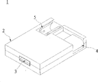
Fig. 2 is the three-dimensional combination figure of the utility model hub device first embodiment.
Fig. 3 is the three-dimensional combination figure of the utility model hub device second embodiment.
Fig. 4 is the three-dimensional combination figure of the utility model hub device the 3rd embodiment.
Fig. 5 is the three-dimensional combination figure of the utility model hub device the 4th embodiment.
Fig. 6 is the three-dimensional combination figure of the utility model hub device the 5th embodiment.
Wherein,
1 hub device
2 main bodys
20 upper cover body, 21 lower covers
22 spatial accommodations, 23 openings
24 circuit boards
25 electric transformational structures
251 first power transformers, 252 second source transformers
3 signal connection end mouths
4 Signal plug groups
40 Signal plugs, 41 signal transmssion lines
5 attaching plug groups
50 attaching plugs
Embodiment
See also Fig. 1 and shown in Figure 2, be the correlative type of the utility model hub device first embodiment.This hub device 1 comprises: a main body 2, a plurality of signal connection end mouth 3, a Signal plug group 4 and an attaching plug group 5.
This main body 2 is made up of a upper cover body 20 and a lower cover 21, by the cooperation between this upper and lower cover body 20,21, is positioned at the spatial accommodation 22 of main body 2 and the opening 23 of a plurality of perforation main bodys 2 to form one.This spatial accommodation 22 can be installed with the electric transformational structure 25 that a circuit board 24 and is electrically connected on circuit board 24.In embodiment of the present utility model, this circuit board 24 is a printed circuit board (PCB).This electricity transformational structure 25 is a power supply transformation structure, and this power supply transformation structure has one first power transformer 251 and a second source transformer 252, in order to alternating voltage (for example: 100 volts~240 volts voltages) or direct voltage convert direct voltage to.
Signal connection end mouth 3 is a universal serial bus concentrator USB specification, and a plurality of signal connection end mouths 3 are located at respectively in this main body 2, and corresponding to opening 23.Each signal connection end mouth 3 is electrically connected on the circuit board 24.By circuit board 24 and electric transformational structure 25 electrically conduct and voltage transitions is handled, provide DC power supply to each signal connection end mouth 3, be connected in the required power source of signal connection end mouth 3 as various electronic installations.In concrete application, signal connection end mouth 3 can be applied to the transmission between desktop PC, mobile computer, flat computer, mobile phone, palmtop computer and computer peripheral device.
Attaching plug group 5 is hubbed on this main body 2, and is electrically connected on the second source transformer 252 of this electricity transformational structure 25, and independently power source is provided.Wherein, attaching plug group 5 has an attaching plug 50, but self turns to the use location, attaching plug 50 is plugged on the external power receptacle (figure does not show) easily, in order to an external power source to be provided, make that with this external power source can be via this attaching plug group 5 to second source transformer 252, as the independent current source of hub device 1.
Therefore, when hub device 1 did not use, Signal plug group 4 and attaching plug group 5 can be contained in the main body 2, to be convenient for carrying.When hub device 1 in use, signal connection end mouth 3 can provide the connection of electronic installation, carries out the data between each electronic installation; And Signal plug group 4 is connected on the computer, carries out the data of supply of electric power and each electronic installation.When if hub device 1 is not connected in computer, still can be connected in an external power source by the attaching plug 50 of attaching plug group 5, make hub device 1 as a charging device, at the action of charging of various electronic installations, the line data signal of going forward side by side transmission, therefore, hub device 1 both can charge and data simultaneously, also can charge respectively or data.
In the utility model, attaching plug 50 can be the plug of a USB specification; Perhaps, can be a tripod or a bipod joint that is applicable to the AC power specification; Perhaps, can be an attaching plug as the DC power supply input.In the present embodiment, attaching plug 50 is one to be applicable to the bipod joint of AC power specification.
See also shown in Figure 3ly, be the correlative type of the utility model hub device second embodiment.The difference of the present embodiment and first embodiment is:
The Signal plug group 4 of hub device 1 is a coiling apparatus, signal transmssion line 41 can elasticity be crispaturaed, at random to prolong or to shorten length, make the activity space of Signal plug 40 increase, can optionally be stretched to the different plug-in positions of computer equipment (or other electronic installation).
See also shown in Figure 4ly, be the correlative type of the utility model hub device the 3rd embodiment.The present embodiment and first difference of implementing are:
See also Fig. 5 and shown in Figure 6, be respectively the correlative type of the utility model hub device the 4th and the 5th embodiment.The difference that fourth, fifth embodiment and first implements is: all Signal plug groups 4 all can be utilized the mode of pivot, but self are located at rotationally on this main body 2, make one or more Signal plugs 4 peg graft use or accommodate fixing on.During use, can select Signal plug 4 is turned to the use location, with the convenience of raising use, and the portability of increase hub device.
In sum, the utility model hub device has following characteristics:
1, utilize Signal plug group and attaching plug group to be electrically connected on electric transformational structure, make hub device that the stable external power source can be provided, the signal connection end mouth is good to keep, stable power, improves the stability of electronic installation running.
Even under the situation of 2 computer installation faults or not start, can be plugged in external power source by the attaching plug group, make hub device be used as a cradle, think various electronic installation power supplies, and provide the good data signal transmission quality for electronic installation.
If 3 to be plugged in the electronic installation of signal connection end mouth less, user's can select to use a computer power supply of supply of equipment makes hub device provide power supply to electronic installation, carries out the data of electronic installation.
4, the use by attaching plug group and Signal plug group, can between different electronic installations, carry out data, and,, also can charge separately or data so both can charge simultaneously and data at the electronic installation action of charging.
The above only is a preferred implementation of the present utility model; should be pointed out that for those skilled in the art, under the prerequisite that does not break away from the utility model principle; can also make some improvements and modifications, these improvements and modifications also should be considered as protection range of the present utility model.
Claims (10)
1. a hub device is characterized in that, comprising:
One main body, inside are provided with the electric transformational structure that a circuit board and is electrically connected on this circuit board;
A plurality of signal connection end mouths are located in this main body and are electrically connected on this circuit board;
One Signal plug group is located on this main body, and this Signal plug group is electrically connected on this electricity transformational structure, and this Signal plug group has a Signal plug; And
One attaching plug group is hubbed on this main body, and this attaching plug group is electrically connected on this electricity transformational structure, and this attaching plug group has an attaching plug.
2. hub device as claimed in claim 1, it is characterized in that, this main body has a upper cover body and a lower cover, this upper and lower cover body corresponds to each other to form a spatial accommodation and a plurality of opening, ccontaining this circuit board of this spatial accommodation, electric transformational structure and signal connection end mouth, and this signal connection end mouth is corresponding to described a plurality of openings.
3. hub device as claimed in claim 1, it is characterized in that, this electricity transformational structure is a power supply transformation structure, this power supply transformation structure has at least two power transformers, be electrically connected with this Signal plug group and this attaching plug group respectively, change alternating voltage or direct voltage and become direct voltage.
4. hub device as claimed in claim 1 is characterized in that, also comprises a plurality of Signal plug groups, and described a plurality of Signal plug groups are hubbed at respectively on this main body.
5. hub device as claimed in claim 1 is characterized in that, this Signal plug group is a coiling apparatus.
6. hub device as claimed in claim 1 is characterized in that, also comprises a plurality of Signal plug groups, and described a plurality of Signal plug groups are a coiling apparatus.
7. hub device as claimed in claim 1 is characterized in that, described a plurality of signal connection end mouths and this Signal plug group are the universal serial bus concentrator specification.
8. hub device as claimed in claim 1 is characterized in that, this attaching plug is the plug of a universal serial bus concentrator specification.
9. hub device as claimed in claim 1 is characterized in that, this attaching plug is one to be applicable to the tripod or the bipod joint of AC power specification.
10. hub device as claimed in claim 1 is characterized in that, this attaching plug is an attaching plug as the direct voltage input.
Priority Applications (1)
| Application Number | Priority Date | Filing Date | Title |
|---|---|---|---|
| CNU2008201340829U CN201278423Y (en) | 2008-09-19 | 2008-09-19 | Hub set |
Applications Claiming Priority (1)
| Application Number | Priority Date | Filing Date | Title |
|---|---|---|---|
| CNU2008201340829U CN201278423Y (en) | 2008-09-19 | 2008-09-19 | Hub set |
Publications (1)
| Publication Number | Publication Date |
|---|---|
| CN201278423Y true CN201278423Y (en) | 2009-07-22 |
Family
ID=40896012
Family Applications (1)
| Application Number | Title | Priority Date | Filing Date |
|---|---|---|---|
| CNU2008201340829U Expired - Fee Related CN201278423Y (en) | 2008-09-19 | 2008-09-19 | Hub set |
Country Status (1)
| Country | Link |
|---|---|
| CN (1) | CN201278423Y (en) |
Cited By (3)
| Publication number | Priority date | Publication date | Assignee | Title |
|---|---|---|---|---|
| CN102570223A (en) * | 2010-12-08 | 2012-07-11 | 胜德国际研发股份有限公司 | Detachable electric information display socket module |
| CN103701174A (en) * | 2013-12-30 | 2014-04-02 | 深圳市强大实业有限公司 | Portable multipath communication charging device capable of charging electrical appliances of different types |
| CN107112778A (en) * | 2016-12-28 | 2017-08-29 | 深圳市大疆灵眸科技有限公司 | Switching device, head and the control method based on head |
-
2008
- 2008-09-19 CN CNU2008201340829U patent/CN201278423Y/en not_active Expired - Fee Related
Cited By (7)
| Publication number | Priority date | Publication date | Assignee | Title |
|---|---|---|---|---|
| CN102570223A (en) * | 2010-12-08 | 2012-07-11 | 胜德国际研发股份有限公司 | Detachable electric information display socket module |
| CN102570223B (en) * | 2010-12-08 | 2014-04-02 | 胜德国际研发股份有限公司 | Detachable electric information display socket module |
| CN103701174A (en) * | 2013-12-30 | 2014-04-02 | 深圳市强大实业有限公司 | Portable multipath communication charging device capable of charging electrical appliances of different types |
| CN103701174B (en) * | 2013-12-30 | 2016-05-11 | 深圳市强大实业有限公司 | The portable multipath that can be the charging of the dissimilar electric equipment charging device of can communicating by letter |
| CN107112778A (en) * | 2016-12-28 | 2017-08-29 | 深圳市大疆灵眸科技有限公司 | Switching device, head and the control method based on head |
| WO2018119737A1 (en) * | 2016-12-28 | 2018-07-05 | 深圳市大疆灵眸科技有限公司 | Transfer apparatus, pan-tilt and control method based on pan-tilt |
| CN107112778B (en) * | 2016-12-28 | 2021-07-30 | 深圳市大疆灵眸科技有限公司 | Switching device, holder and holder-based control method |
Similar Documents
| Publication | Publication Date | Title |
|---|---|---|
| CN108718020B (en) | Concentrator | |
| EP2985856B1 (en) | Usb charging system with variable charging voltage, charger, and intelligent terminal | |
| CN102437623B (en) | Adapter, terminal device, USB (universal serial bus) connection device and charging base station | |
| CN102255481B (en) | Power manager | |
| WO2007047453A2 (en) | Power adapter | |
| CN110289972B (en) | Network equipment and network system based on Ethernet | |
| CN201278423Y (en) | Hub set | |
| CN103885564A (en) | Power supply adapter plate, power supply system and electronic equipment with power supply system | |
| CN201251760Y (en) | Power supply device of direct current power supply capable of outputting correct voltage according to electrical equipment | |
| CN110336351B (en) | USB quick charging device with data transmission function | |
| CN202025920U (en) | Power supply manager | |
| CN201142371Y (en) | USB hub | |
| CN201252310Y (en) | Alternating current power supply distributor with a plurality of direct current power supply outputs and USB interfaces | |
| CN103001081A (en) | Novel USB (universal serial bus) hub | |
| CN201260134Y (en) | Electric power supply device having multiple output ports | |
| CN207833498U (en) | A kind of built-up circuit and device of mobile device | |
| CN202618660U (en) | Solar protective sleeve for electronic reader | |
| CN207559221U (en) | A kind of Multifunctional data line | |
| CN203277901U (en) | Signal power supply integrated module | |
| CN217334603U (en) | Wire concentrator | |
| US20180011523A1 (en) | Power adapter with i/o ports | |
| CN203056293U (en) | USB interface panel plug-in unit | |
| CN216355037U (en) | Charging adapter with wire harness arranging function | |
| CN219285717U (en) | MCU and NorFlash burn two unification keysets | |
| CN109375758B (en) | Charging device for computer host configuration |
Legal Events
| Date | Code | Title | Description |
|---|---|---|---|
| C14 | Grant of patent or utility model | ||
| GR01 | Patent grant | ||
| C17 | Cessation of patent right | ||
| CF01 | Termination of patent right due to non-payment of annual fee |
Granted publication date: 20090722 Termination date: 20100919 |