CN201245970Y - Casting formwork unit - Google Patents
Casting formwork unit Download PDFInfo
- Publication number
- CN201245970Y CN201245970Y CNU2008201484030U CN200820148403U CN201245970Y CN 201245970 Y CN201245970 Y CN 201245970Y CN U2008201484030 U CNU2008201484030 U CN U2008201484030U CN 200820148403 U CN200820148403 U CN 200820148403U CN 201245970 Y CN201245970 Y CN 201245970Y
- Authority
- CN
- China
- Prior art keywords
- pillar
- strut
- modular unit
- top board
- standard modular
- Prior art date
- Legal status (The legal status is an assumption and is not a legal conclusion. Google has not performed a legal analysis and makes no representation as to the accuracy of the status listed.)
- Expired - Fee Related
Links
- 238000009415 formwork Methods 0.000 title abstract 3
- 238000005266 casting Methods 0.000 title 1
- 210000002435 tendon Anatomy 0.000 claims description 8
- 230000000694 effects Effects 0.000 claims description 3
- 239000011150 reinforced concrete Substances 0.000 abstract description 2
- XEEYBQQBJWHFJM-UHFFFAOYSA-N Iron Chemical compound [Fe] XEEYBQQBJWHFJM-UHFFFAOYSA-N 0.000 description 4
- 230000002787 reinforcement Effects 0.000 description 3
- 239000004567 concrete Substances 0.000 description 2
- 238000010276 construction Methods 0.000 description 2
- 238000010586 diagram Methods 0.000 description 2
- 229910052742 iron Inorganic materials 0.000 description 2
- 229910000831 Steel Inorganic materials 0.000 description 1
- 238000005516 engineering process Methods 0.000 description 1
- 238000000034 method Methods 0.000 description 1
- 239000000203 mixture Substances 0.000 description 1
- 238000000926 separation method Methods 0.000 description 1
- 239000010959 steel Substances 0.000 description 1
- 238000005728 strengthening Methods 0.000 description 1
Images



Landscapes
- Joining Of Building Structures In Genera (AREA)
Abstract
The utility model discloses a standard formwork unit for supporting reinforced concrete at the top of a building work, which comprises a top plate (1), a strut (2) movably connected with the top plate (1), and a backing plate movably connected with the strut (2). Two orthogonal level bars (4) are arranged on one cross section of the strut (2). The strut (2) comprises a threaded stud (5) and a stud cylinder (6) matching with the threaded stub through a thread, and a scale is formed on the stud (5) along the longitudinal direction. A plurality of concave spherical surfaces (8) are formed on the lower surface of the top plate (1), convex spherical surfaces (9) matching with the concave spherical surfaces (8) are formed at the top end of the strut (2), and positioning holes (10) and positioning pins (11) are arranged at the combining sites of the concave spherical surfaces (8) and the convex spherical surfaces (9). The standard formwork unit can easily enable the strut to be vertically placed, so as to improve supporting weight by adjusting the height of the strut. The connection way of the top plate and the strut can improve the connection stability.
Description
Technical field
The utility model belongs to the building engineering equipment field, relates in particular to the concrete standard modular unit of a kind of support construction work top rebars.
Background technology
At present, reinforced concrete works commonly used mainly in two kinds of situation, a kind of is traditional steel pipe iron sheet pattern, but because iron sheet easy deformation in the process of using, and just is difficult to reach the smooth engine request of supporting surface after using several times; The wooden template that another is relatively more commonly used, because the intensity reason of template, the numerous pillar of supported amount below the wooden template, can the concrete purpose of bearing bar to reach template, but the workload of installing, dismantle wooden template braced structures is very big, and the reusable number of times of wooden template is limited, must upgrade Cheng Mugao after using for several times.
The utility model content
The utility model provides a kind of structural strength big, and stability is strong, and support effect is good, bearing height, adjustable standard modular unit easy to use.
A kind of standard modular unit, comprise top board, the pillar that is connected with roof movement, with the movable backing plate that connects of pillar, a cross section of described pillar is provided with two orthogonal spirit levels.
Described pillar is formed by double-screw bolt with by the column casing that silking matches with double-screw bolt.
Be provided with scale on the described double-screw bolt along its length.
The bottom surface of described top board is provided with the reinforcement convex tendon.
Described top board bottom surface has a plurality of concave spherical surfaces, and the pillar top has the protruding sphere that matches with concave spherical surface on the described top board bottom surface, and the binding site of the protruding sphere on the concave spherical surface of described top board bottom surface and pillar top is provided with locating hole and alignment pin.
Described pillar and backing plate are by being threaded.
Described standard modular unit is provided with the self-locking mechanism that is connected with other unit.
Because the cross section of the utility model standard modular unit pillar is provided with two orthogonal spirit levels, can reach the vertical placement of pillar easily; Pillar is formed by double-screw bolt with by the column casing that silking matches with double-screw bolt, can adjust the height of pillar, to adapt to the needs of different bearing heights; Top board is arranged with the reinforcement convex tendon, can strengthen the intensity of self, to improve the weight that supports; Be provided with scale on the double-screw bolt of described pillar along its length, can easily determine the height that double-screw bolt stretches out; The connected mode of the protruding sphere on the concave spherical surface of top board bottom surface and pillar top, and the locating hole and the locating pin structure of connecting portion can improve both connection stability.
Description of drawings
Fig. 1 is the utility model standard modular unit top board bottom surface structural representation;
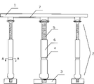
Fig. 2 is the structural representation of the utility model standard modular unit;
Fig. 3 is the syndeton schematic diagram of standard modular unit top board and pillar;
Fig. 4 is the sectional view of spirit level shown in Figure 2 along the A-A line;
Fig. 5 is the syndeton schematic diagram of standard modular unit and other unit.
The specific embodiment
As shown in Figure 1, 2, a kind of standard modular unit, the pillar 2 that comprises top board 1, flexibly connects with top board 1, with the backing plates 3 that pillar 2 activities connect, a cross section of described pillar 2 is provided with two orthogonal spirit levels 4, described spirit level 4 is embedded on the pillar 2, is convenient to construction.Described pillar 2 is formed by double-screw bolt 5 with by the column casing 6 that silking matches with double-screw bolt 5, the height of described pillar 2 can lead to the purpose that rotation double-screw bolt 5 reaches adjustment, be provided with scale along its length on the described double-screw bolt 5, have scale on the double-screw bolt 5, conveniently determine the height that double-screw bolt 5 screws out when being convenient to construct, and then judge the height of pillar easily.The bottom surface of described top board 1 is provided with strengthens convex tendon 7, is provided with many under the top board and strengthens the quality that convex tendon 7 helps improving top plate supporting, and the shape of preferably strengthening the convex tendon composition is the quadrangle of diagonal angle line.
Described top board 1 bottom surface has a plurality of concave spherical surfaces 8, concave spherical surface 8 preferably is provided with the intersection point place that strengthens convex tendon 7, a preferred quantity is 5, pillar 2 tops have the protruding sphere 9 that matches with concave spherical surface 8 on described top board 1 bottom surface, the quantity of corresponding pillar 2 also is 5, the concave spherical surface 8 of described top board 1 bottom surface is provided with locating hole 10 and alignment pin 11 with the binding site of the protruding sphere 9 on pillar 2 tops, the concave spherical surface 8 that utilizes top board 1 bottom surface when the standard modular unit is installed is provided with locating hole 10 with the binding site of the protruding sphere 9 on pillar 2 tops and alignment pin 11 carries out both fixing, during dismounting, pull up alignment pin 11 from locating hole 10 and can finish both separation.
Described pillar 2 and backing plate 3 are by being threaded, and the height of described pillar 2 can also be by installing the increase height of some sprags additional, and described pillar 2 is connected with sprag by screw thread.
Described standard modular unit is provided with the self-locking mechanism 12 that is connected with other unit, the formula modular unit is finished the combination of any two standard modular units by the self-locking mechanism 12 on four limits, have certain stability to guarantee to be connected, and the upper surface of a plurality of top boards in back that are connected in one plane.
Because the cross section of the utility model standard modular unit pillar is provided with two orthogonal spirit levels, can reach the vertical placement of pillar easily; Pillar is formed by double-screw bolt with by the column casing that silking matches with double-screw bolt, can adjust the height of pillar, to adapt to the needs of different bearing heights; Top board is arranged with the reinforcement convex tendon, can strengthen the intensity of self, to improve the weight that supports; Be provided with scale on the double-screw bolt of described pillar along its length, can easily determine the height that double-screw bolt stretches out; The connected mode of the protruding sphere on the concave spherical surface of top board bottom surface and pillar top, and the locating hole and the locating pin structure of connecting portion can improve both connection stability.
Claims (7)
1. standard modular unit, the pillar (2) that comprises top board (1), flexibly connects with top board (1), with the backing plate (3) that pillar (2) activity connects, it is characterized in that: a cross section of described pillar (2) is provided with two orthogonal spirit levels (4).
2. standard modular unit as claimed in claim 1 is characterized in that: described pillar (2) is formed by double-screw bolt (5) with by the column casing (6) that silking matches with double-screw bolt (5).
3. standard modular unit as claimed in claim 2 is characterized in that: described double-screw bolt is provided with scale on (5) along its length.
4. standard modular unit as claimed in claim 1 is characterized in that: the bottom surface of described top board (1) is provided with strengthens convex tendon (7).
5. as described any standard modular unit of claim 1 to 4, it is characterized in that: described top board (1) bottom surface has a plurality of concave spherical surfaces (8), pillar (2) top has the protruding sphere (9) that matches with concave spherical surface (8) on described top board (1) bottom surface, and the concave spherical surface (8) of described top board (1) bottom surface is provided with locating hole (10) and alignment pin (11) with the binding site of the protruding sphere (9) on pillar (2) top.
6. standard modular unit as claimed in claim 5 is characterized in that: described pillar (2) and backing plate (3) are by being threaded.
7. standard modular unit as claimed in claim 5 is characterized in that: described standard modular unit is provided with the self-locking mechanism (12) that is connected with other unit.
Priority Applications (1)
| Application Number | Priority Date | Filing Date | Title |
|---|---|---|---|
| CNU2008201484030U CN201245970Y (en) | 2008-07-28 | 2008-07-28 | Casting formwork unit |
Applications Claiming Priority (1)
| Application Number | Priority Date | Filing Date | Title |
|---|---|---|---|
| CNU2008201484030U CN201245970Y (en) | 2008-07-28 | 2008-07-28 | Casting formwork unit |
Publications (1)
| Publication Number | Publication Date |
|---|---|
| CN201245970Y true CN201245970Y (en) | 2009-05-27 |
Family
ID=40729790
Family Applications (1)
| Application Number | Title | Priority Date | Filing Date |
|---|---|---|---|
| CNU2008201484030U Expired - Fee Related CN201245970Y (en) | 2008-07-28 | 2008-07-28 | Casting formwork unit |
Country Status (1)
| Country | Link |
|---|---|
| CN (1) | CN201245970Y (en) |
Cited By (5)
| Publication number | Priority date | Publication date | Assignee | Title |
|---|---|---|---|---|
| CN102513929A (en) * | 2011-11-11 | 2012-06-27 | 武汉长盈通光电技术有限公司 | Combined fixture used for fixing optical fiber stress rod |
| CN102605946A (en) * | 2012-04-18 | 2012-07-25 | 新蒲建设集团有限公司 | Device and method for quickly detaching concrete floor slab shuttering |
| CN104947958A (en) * | 2015-07-20 | 2015-09-30 | 苏州新达电扶梯部件有限公司 | Adjustable support frame for truss assembly |
| CN109203189A (en) * | 2018-09-10 | 2019-01-15 | 浙江南洋水泥制品有限公司 | A kind of technique manufacturing curved surface cement products pre-member for building |
| CN109779292A (en) * | 2019-01-23 | 2019-05-21 | 深圳市润飞建筑劳务有限公司 | A kind of aluminum alloy pattern plate bracing device |
-
2008
- 2008-07-28 CN CNU2008201484030U patent/CN201245970Y/en not_active Expired - Fee Related
Cited By (5)
| Publication number | Priority date | Publication date | Assignee | Title |
|---|---|---|---|---|
| CN102513929A (en) * | 2011-11-11 | 2012-06-27 | 武汉长盈通光电技术有限公司 | Combined fixture used for fixing optical fiber stress rod |
| CN102605946A (en) * | 2012-04-18 | 2012-07-25 | 新蒲建设集团有限公司 | Device and method for quickly detaching concrete floor slab shuttering |
| CN104947958A (en) * | 2015-07-20 | 2015-09-30 | 苏州新达电扶梯部件有限公司 | Adjustable support frame for truss assembly |
| CN109203189A (en) * | 2018-09-10 | 2019-01-15 | 浙江南洋水泥制品有限公司 | A kind of technique manufacturing curved surface cement products pre-member for building |
| CN109779292A (en) * | 2019-01-23 | 2019-05-21 | 深圳市润飞建筑劳务有限公司 | A kind of aluminum alloy pattern plate bracing device |
Similar Documents
| Publication | Publication Date | Title |
|---|---|---|
| CN101858055A (en) | Setting steel pipe bracket support system of cover beam and construction method thereof | |
| CN208748843U (en) | A kind of stiffness structure bean column node fashioned iron and steel bar connecting structure | |
| CN204492134U (en) | Be convenient to the height scaffolding installed | |
| CN209779689U (en) | Pipe gallery construction aluminum mould board integral type inner support device | |
| CN201428249Y (en) | Building template supporting structure | |
| CN103255929A (en) | Assembly technology of adjustable supporting columns and eight type modularized steel floor slab moulds | |
| CN207175252U (en) | A kind of artificial panel turnover machine for being used to overturn prefabricated panel | |
| CN210002942U (en) | transformation structure of old building brick column | |
| CN218881642U (en) | Simple positioning device for embedded anchor bolts of steel column base of prefabricated steel structure house steel column | |
| CN201605793U (en) | Moving clamping piece of overhanging steel frame | |
| CN216973954U (en) | Detachable bottom plate T-shaped hanging structure of steel bar truss floor bearing plate | |
| CN214942312U (en) | Large-plane vertical template structure without rivet fixation | |
| CN214061288U (en) | Bearing box girder template | |
| CN205134291U (en) | Large -scale steel form with adjustable | |
| CN210122816U (en) | Be used for assembled coincide floor bottom plate board seam template reinforcing apparatus | |
| CN219886552U (en) | Upright post structure of steel bridge | |
| CN211286609U (en) | Descending plate formwork supporting tool | |
| CN208329608U (en) | Vertical metope connects inner corner trim and building template unit with Roofing slab | |
| CN206071051U (en) | Building deformation joint Concrete Double wall supporting and positioning device | |
| CN211114903U (en) | Pre-buried bolt accuracy control device | |
| CN219508836U (en) | Pre-buried waterproof base for steel structure support | |
| CN206625604U (en) | A kind of lightweight steel construction component of quick construction | |
| CN206873922U (en) | A kind of dismountable steel bar truss floor support plate cheek board attachment structure of end template | |
| CN223214807U (en) | Combined floor support structure | |
| CN219045302U (en) | Engineering construction stand pouring support template |
Legal Events
| Date | Code | Title | Description |
|---|---|---|---|
| C14 | Grant of patent or utility model | ||
| GR01 | Patent grant | ||
| C17 | Cessation of patent right | ||
| CF01 | Termination of patent right due to non-payment of annual fee |
Granted publication date: 20090527 Termination date: 20100728 |