CN201189018Y - Mounting rack of mosquito net rack - Google Patents
Mounting rack of mosquito net rack Download PDFInfo
- Publication number
- CN201189018Y CN201189018Y CNU2008200983370U CN200820098337U CN201189018Y CN 201189018 Y CN201189018 Y CN 201189018Y CN U2008200983370 U CNU2008200983370 U CN U2008200983370U CN 200820098337 U CN200820098337 U CN 200820098337U CN 201189018 Y CN201189018 Y CN 201189018Y
- Authority
- CN
- China
- Prior art keywords
- mosquito net
- hem
- installing rack
- width
- slide rail
- Prior art date
- Legal status (The legal status is an assumption and is not a legal conclusion. Google has not performed a legal analysis and makes no representation as to the accuracy of the status listed.)
- Expired - Fee Related
Links
- 241000255925 Diptera Species 0.000 title claims abstract description 30
- 210000001503 joint Anatomy 0.000 claims 2
- 241000238631 Hexapoda Species 0.000 abstract 1
- 238000009434 installation Methods 0.000 description 11
- 238000010586 diagram Methods 0.000 description 4
- 230000007812 deficiency Effects 0.000 description 1
- 238000000034 method Methods 0.000 description 1
Images




Classifications
-
- Y—GENERAL TAGGING OF NEW TECHNOLOGICAL DEVELOPMENTS; GENERAL TAGGING OF CROSS-SECTIONAL TECHNOLOGIES SPANNING OVER SEVERAL SECTIONS OF THE IPC; TECHNICAL SUBJECTS COVERED BY FORMER USPC CROSS-REFERENCE ART COLLECTIONS [XRACs] AND DIGESTS
- Y02—TECHNOLOGIES OR APPLICATIONS FOR MITIGATION OR ADAPTATION AGAINST CLIMATE CHANGE
- Y02A—TECHNOLOGIES FOR ADAPTATION TO CLIMATE CHANGE
- Y02A50/00—TECHNOLOGIES FOR ADAPTATION TO CLIMATE CHANGE in human health protection, e.g. against extreme weather
- Y02A50/30—Against vector-borne diseases, e.g. mosquito-borne, fly-borne, tick-borne or waterborne diseases whose impact is exacerbated by climate change
Landscapes
- Curtains And Furnishings For Windows Or Doors (AREA)
Abstract
Description
技术领域 technical field
本实用新型涉及一种蚊帐架安装架。The utility model relates to a mosquito net frame mounting frame.
背景技术 Background technique
现有的蚊帐架安装架,其安装架是单滑轨的。安装时,需将安装架互相重叠,才能使蚊帐有重叠的部份,比较浪费材料,安装不方便,外形也不美观。Existing mosquito net frame installation frame, its installation frame is single slide rail. During installation, the installation frames need to be overlapped with each other, so that the mosquito net has overlapping parts, which wastes materials, is inconvenient to install, and has an unattractive appearance.
实用新型内容Utility model content
本实用新型的目的是克服现有技术的不足而提供一种安装时,安装架不需重叠也能使蚊帐开口处重叠,安装方便,外形美观的蚊帐架安装架。The purpose of this utility model is to overcome the deficiencies of the prior art and provide a mosquito net rack that can overlap the openings of the mosquito net without overlapping the mounting racks during installation, which is convenient to install and has a beautiful appearance.
为了达到上述目的,本实用新型是这样实现的,其是一种蚊帐安装架,其包括安装蚊帐用的安装架,其特征在于:安装架的断面呈“匚”形,其包括上折边、下折边及连接上下折边的垂直边,上折边的宽度大于或等于下折边的宽度;在上折边上设有互相平行且位置互相对应的内滑轨及外滑轨,下折边的宽度大于或等于外滑轨的宽度,从而可以有效的防止蚊虫进入蚊帐内。In order to achieve the above object, the utility model is achieved in that it is a mosquito net mounting frame, which includes a mounting frame for installing a mosquito net, and is characterized in that: the cross section of the mounting frame is "匚" shape, which includes upper folds, The lower fold and the vertical edge connecting the upper and lower folds, the width of the upper fold is greater than or equal to the width of the lower fold; on the upper fold, there are inner slide rails and outer slide rails that are parallel to each other and their positions correspond to each other. The width of the side is greater than or equal to the width of the outer slide rail, thereby effectively preventing mosquitoes from entering the mosquito net.
在所述的上折边上设有起连接用的上连接槽,从而使形状相同的安装架实现对接。An upper connection groove for connection is provided on the upper folded edge, so that the installation frames with the same shape can be docked.
在所述的下折边上设有起连接用的下连接槽,从而使形状相同的安装架实现对接。A lower connection groove for connection is provided on the lower folded edge, so that the installation frames with the same shape can be docked.
所述的的上连接槽设在在内滑轨及外滑轨之间。The above connecting groove is arranged between the inner slide rail and the outer slide rail.
在所述的下折边上还可设有安装装饰管用的卡码。A card code for installing decorative tubes may also be provided on the lower folded edge.
本实用新型与现有技术相比的优点为,由于安装架带有双滑轨,其不需重叠也能使蚊帐开口处重叠,安装方便,结构简单,外形美观。Compared with the prior art, the utility model has the advantages that the opening of the mosquito net can be overlapped without overlapping because the mounting frame has double slide rails, and the installation is convenient, the structure is simple, and the appearance is beautiful.
附图说明 Description of drawings
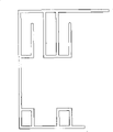
图1是本实用新型的第一种实施例的结构示意图;Fig. 1 is the structural representation of the first kind of embodiment of the utility model;
图2是本实用新型的第二种实施例的结构示意图;Fig. 2 is the structural representation of the second embodiment of the utility model;
图3是本实用新型的第三种实施例的结构示意图;Fig. 3 is the structural representation of the third embodiment of the utility model;
图4是本实用新型的第四种实施例的结构示意图;Fig. 4 is the structural representation of the fourth embodiment of the utility model;
图5是本实用新型的第五种实施例的结构示意图;Fig. 5 is the structural representation of the fifth embodiment of the present utility model;
图6是本实用新型的第六种实施例的结构示意图;Fig. 6 is a schematic structural view of a sixth embodiment of the present invention;
图7是本实用新型的第七种实施例的结构示意图;Fig. 7 is the structural representation of the seventh embodiment of the present utility model;
图8是本实用新型的第八种实施例的结构示意图;Fig. 8 is a schematic structural view of an eighth embodiment of the present utility model;
图9是本实用新型的第九种实施例的结构示意图;Fig. 9 is a schematic structural view of a ninth embodiment of the present invention;
图10是本实用新型的第十种实施例的结构示意图;Fig. 10 is a schematic structural view of a tenth embodiment of the present utility model;
图11是本实用新型的第十一种实施例的结构示意图;Fig. 11 is a structural schematic diagram of an eleventh embodiment of the present utility model;
图12是本实用新型的第十二种实施例的结构示意图;Fig. 12 is a schematic structural view of a twelfth embodiment of the present utility model;
图13是本实用新型的第一种实施例装配滑轮及卡码的结构示意图;Fig. 13 is a structural schematic diagram of the first embodiment of the utility model for assembling the pulley and the card code;
图14是本实用新型的使用状态图;Fig. 14 is the use state figure of the utility model;
图15是本实用新型使用时拉绳的一种布置图;Fig. 15 is a kind of arrangement diagram of stay rope when the utility model is used;
图16是本实用新型使用时拉绳的另一种布置图。Fig. 16 is another arrangement diagram of stay rope when the utility model is in use.
具体实施方式 Detailed ways
下面将结合附图和实施例对本实用新型做进一步详述:Below in conjunction with accompanying drawing and embodiment the utility model is described in further detail:
实施例一Embodiment one
如图1所示,其是一种蚊帐架安装架,其包括安装蚊帐用的安装架,安装架1的断面呈“匚”形,其包括上折边4、下折边7及连接上下折边的垂直边5,上折边的宽度大于或等于下折边的宽度;在上折边上设有互相平行且位置互相对应的内滑轨1及外滑轨3,内、外滑轨的开口均往右;在上折边4上设有起连接用的上连接槽2,该上连接槽与外滑轨共用一纵壁,下折边上设有起连接用的下连接槽6,下连接槽为一个连接孔,从而使形状相同的安装架实现对接。下折边的宽度大于或等于外滑轨的宽度,从而可以有效的防止蚊虫进入蚊帐内,在其的下方设有安装装饰管10用的卡码9,从而可以将下折边隐藏起来。As shown in Figure 1, it is a kind of mosquito net frame mounting frame, and it comprises the mounting frame that mosquito net is installed, and the section of mounting frame 1 is " 匚 " shape, and it comprises upper folded
由于在安装架上的有内、外滑轨,在其上可以安装两排带钩的滑轮8,其钩可与蚊帐相连,如图13、14所示,因此其可以带动蚊帐往两个方向移动,在安装时,安装架不需要重叠即可实现蚊帐开口处重叠,安装使用非常方便。由于有上连接槽2及下连接槽6,在其内可设连接杆,因此可以将形状相同的安装架实现对接。如图15所示,在安装架的一端固定有一滑轮11,在另一端固定有两只滑轮14、15,其中滑轮14,还有自动锁定装置,拉绳12绕过滑轮11后,一端再绕过滑轮14拉动,在该段绳上设有一带钩的滑块13,该钩可与蚊帐相连;另一端再绕过滑轮15拉动,在该段绳上设有另一带钩的滑块,该钩可与蚊帐相连。使用时拉动拉绳即可带动蚊帐的开合。如图16所示,在安装架的一端固定有一滑轮11,在另一端固定有两只滑轮14,拉绳12绕过滑轮11后,一端再绕过滑轮14拉动,在该段绳上设有一带钩的滑块13,在滑块13与滑轮11之间还设有拉簧16;另一端设有另一带钩的滑块,该滑块的另一端还与另一拉簧17连接,拉簧的另一端与拉绳连接,从而可以自动打开。Because the inside and outside slide rails are arranged on the mounting rack, two rows of hooked pulleys 8 can be installed on it, and its hooks can be connected with the mosquito net, as shown in Figures 13 and 14, so it can drive the mosquito net to two directions When moving, during installation, the installation frame does not need to overlap to realize the overlapping of the opening of the mosquito net, which is very convenient to install and use. Because there are upper connecting
实施例二Embodiment two
如图2所示,其它的与实施例一一样,所不同的是内外滑轨1、3的开口方向不同,内滑轨的开口往左开,外滑轨的开口往右开;上连接槽2的一纵壁与外滑轨共用一纵壁,其另一纵壁与内滑轨共用一纵壁;下连接槽6有两个连接孔。As shown in Figure 2, the others are the same as the first embodiment, the difference is that the opening directions of the inner and
实施例三Embodiment Three
如图3所示,其它的与实施例一一样,所不同的是上连接槽2呈腰形,下连接槽6有三个连在一起的连接孔。As shown in FIG. 3 , the others are the same as the first embodiment, except that the upper connecting
实施例四Embodiment four
如图4所示,其它的与实施例一一样,所不同的是外滑轨3的纵壁与上连接槽2的底部连接,下连接槽6位于下折边7的中部。As shown in FIG. 4 , the others are the same as the first embodiment, except that the longitudinal wall of the
实施例五Embodiment five
如图5所示,其它的与实施例一一样,所不同的是下连接槽6是两个分离的连接孔。As shown in FIG. 5 , the others are the same as the first embodiment, except that the
实施例六Embodiment six
如图6所示,其它的与实施例一一样,所不同的是下连接槽6是三个连在一起的连接孔。As shown in FIG. 6 , the others are the same as the first embodiment, except that the lower connecting
实施例七Embodiment seven
如图7所示,其它的与实施例一一样,所不同的是下连接槽6在下折边7的中部位置。As shown in FIG. 7 , the others are the same as the first embodiment, except that the
实施例八Embodiment eight
如图8所示,其它的与实施例一一样,所不同的是上连接槽2设在外滑轨3的中下部。As shown in FIG. 8 , the others are the same as the first embodiment, except that the upper connecting
实施例九Embodiment nine
如图9所示,其它的与实施例一一样,所不同的是上连接槽2呈腰形,其内、外滑轨的开口方向不同;在下连接槽6的中部设有一圆形插孔61。As shown in Figure 9, the others are the same as the first embodiment, the difference is that the
实施例十Embodiment ten
如图10所示,其它的与实施例一一样,所不同的是上连接槽2呈腰形,在下连接槽6呈圆形。As shown in FIG. 10 , the others are the same as the first embodiment, except that the
实施例十一Embodiment Eleven
如图11所示,其它的与实施例一一样,所不同的是没有上连接槽。As shown in Figure 11, the others are the same as the first embodiment, except that there is no upper connection groove.
实施例十二
如图12所示,其它的与实施例一一样,所不同的是没有上连接槽,内滑轨1与外滑轨3的开口方向相反,即内滑轨的开口往左,外滑轨的开口往右。As shown in Figure 12, the others are the same as the first embodiment, the difference is that there is no upper connecting groove, the opening direction of the inner slide rail 1 and the
Claims (5)
Priority Applications (1)
| Application Number | Priority Date | Filing Date | Title |
|---|---|---|---|
| CNU2008200983370U CN201189018Y (en) | 2008-05-12 | 2008-05-12 | Mounting rack of mosquito net rack |
Applications Claiming Priority (1)
| Application Number | Priority Date | Filing Date | Title |
|---|---|---|---|
| CNU2008200983370U CN201189018Y (en) | 2008-05-12 | 2008-05-12 | Mounting rack of mosquito net rack |
Publications (1)
| Publication Number | Publication Date |
|---|---|
| CN201189018Y true CN201189018Y (en) | 2009-02-04 |
Family
ID=40333168
Family Applications (1)
| Application Number | Title | Priority Date | Filing Date |
|---|---|---|---|
| CNU2008200983370U Expired - Fee Related CN201189018Y (en) | 2008-05-12 | 2008-05-12 | Mounting rack of mosquito net rack |
Country Status (1)
| Country | Link |
|---|---|
| CN (1) | CN201189018Y (en) |
Cited By (1)
| Publication number | Priority date | Publication date | Assignee | Title |
|---|---|---|---|---|
| CN104665369A (en) * | 2015-03-24 | 2015-06-03 | 李新亚 | Slider Mosquito Net Frame and Mosquito Net |
-
2008
- 2008-05-12 CN CNU2008200983370U patent/CN201189018Y/en not_active Expired - Fee Related
Cited By (2)
| Publication number | Priority date | Publication date | Assignee | Title |
|---|---|---|---|---|
| CN104665369A (en) * | 2015-03-24 | 2015-06-03 | 李新亚 | Slider Mosquito Net Frame and Mosquito Net |
| CN104665369B (en) * | 2015-03-24 | 2017-04-19 | 李新亚 | Slide rail type mosquito net frame and mosquito net |
Similar Documents
| Publication | Publication Date | Title |
|---|---|---|
| CN110281750A (en) | a curved skylight | |
| CN201190490Y (en) | Slide rail structure for translational door | |
| CN205348944U (en) | Convenient tent of opening fast of inflatable | |
| CN107916826A (en) | A kind of gas permeability tent for camping | |
| CN206190184U (en) | Electronic curtain formula solar protection devices | |
| KR200499516Y1 (en) | Quickly openable and closable tent | |
| CN204299338U (en) | Energy saving door and window window frame | |
| CN216713637U (en) | Shutter awning | |
| CN208536319U (en) | Air conditioner dust keeper and air conditioner | |
| CN213330671U (en) | Novel military tent | |
| CN202969771U (en) | Combined type scrollable sunshade frame | |
| CN210598261U (en) | Container house with can fold up ladder of registering one's residence | |
| CN201135289Y (en) | Mosquito net rack | |
| CN201108223Y (en) | a mosquito net | |
| CN103291183A (en) | Energy-saving environment-friendly multifunction window | |
| CN109764037A (en) | A new type of cabinet | |
| CN203064038U (en) | Extensible special type vehicle body | |
| KR100641806B1 (en) | Building Window System Improvement Structure | |
| CN209332517U (en) | A kind of newborn is outgoing to be checked with transhipment van | |
| CN201001551Y (en) | Mosquito net support | |
| CN205370307U (en) | Anti -theft slide window | |
| US20130174989A1 (en) | Weather Queen Roman Shade Assembly | |
| CN201480751U (en) | A wall-mounted drawstring mosquito net | |
| CN205688939U (en) | Suspension type tent | |
| CN223240833U (en) | Outdoor sunshine flower room of convenient assembled |
Legal Events
| Date | Code | Title | Description |
|---|---|---|---|
| C14 | Grant of patent or utility model | ||
| GR01 | Patent grant | ||
| C17 | Cessation of patent right | ||
| CF01 | Termination of patent right due to non-payment of annual fee |
Granted publication date: 20090204 |