CN201188511Y - Busbar shiplap joint row - Google Patents
Busbar shiplap joint row Download PDFInfo
- Publication number
- CN201188511Y CN201188511Y CNU200820102133XU CN200820102133U CN201188511Y CN 201188511 Y CN201188511 Y CN 201188511Y CN U200820102133X U CNU200820102133X U CN U200820102133XU CN 200820102133 U CN200820102133 U CN 200820102133U CN 201188511 Y CN201188511 Y CN 201188511Y
- Authority
- CN
- China
- Prior art keywords
- overlap joint
- joint row
- bus
- tubular metal
- metal body
- Prior art date
- Legal status (The legal status is an assumption and is not a legal conclusion. Google has not performed a legal analysis and makes no representation as to the accuracy of the status listed.)
- Expired - Lifetime
Links
Images
Abstract
The utility model relates to electricity supplying and distributing equipment, in particular to a generatrix related-joint row which comprises a metal tubular body. Both ends of the metal tubular body are pressed to flat shapes, and a related-joint tightening bolt through hole is arranged on each flat bodies. The generatrix related-joint row not only can realize multi-direction and multi-path related joint so as to facilitate the flexible connection of the generatrix and the installation construction on site, but also has simple structure and low manufacture cost.
Description
Technical field
The utility model relates to a kind of power supplying and distributing equipment, particularly a kind of bus overlap joint row.
Background technology
In the prior art, be used to realize that there is following shortcoming in the rectangle row of the multi-direction extension of bus: Electric Field Distribution is not as the pipe bus, and material usage is big under the equal current-carrying, and result of use is poor.And existing on the market pipe bus adopts the embedded connection of spring silk more, the structure relative complex, and the machining accuracy height is difficult to safeguard.
Summary of the invention
The purpose of this utility model is to provide a kind of bus overlap joint row, and this bus overlap joint row not only can realize overlap joint multi-faceted, multiple branch circuit, thereby helps realizing the flexible connection and the on-the-spot installation of bus, and simple in structure, low cost of manufacture.
The technical solution adopted in the utility model is: this bus overlap joint row, comprise tubular metal body, and described tubular metal body two ends are pressed into flat, offer overlap joint fastening bolt through hole on the described flat body.
Distinguishing feature of the present utility model is that bus is processed by metal pipe material, overlapping mode adopts the metal pipe material two ends to be pressed into flat, and " the overlap joint row " that utilize rectangle row to make excessively connects, this overlapping mode can realize that not only bus is multi-faceted, the overlap joint of multiple branch circuit, and it is simple and reliable for structure, be convenient to safeguard, under equal ampacity than rectangle cribbing material saving.
The utility model is described in further detail below in conjunction with drawings and the specific embodiments.
Description of drawings
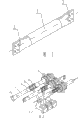
Fig. 1 is the organigram of the utility model embodiment.
Fig. 2 is the user mode schematic diagram of the utility model embodiment.
In Fig. 2,4. the cabinet sleeve pipe 5. is used to connect the rectangle row that adjacent two buses overlap joint is arranged, 6. fastening bolt, 7. contact box.
Embodiment
Bus overlap joint row of the present utility model comprises tubular metal body 1, and described tubular metal body 1 two ends 2 are pressed into flat, offers overlap joint fastening bolt through hole 3 on the described flat body 2.
In order to guarantee to overlap the excellent conductive performance of contact-making surface, above-mentioned tubular metal body is a red copper tubing.
In order to save cost when guaranteeing electric conductivity, above-mentioned tubular metal body also can adopt aluminium tube, and described aluminium tube outer surface is coated with in order to improve the red copper material of electric conductivity.
More than be preferred embodiment of the present utility model, all changes of doing according to technical solutions of the utility model when the function that is produced does not exceed the scope of technical solutions of the utility model, all belong to protection range of the present utility model.
Claims (3)
1. a bus overlap joint row comprises tubular metal body, and it is characterized in that: described tubular metal body two ends are pressed into flat, offers overlap joint fastening bolt through hole on the described flat body.
2. bus overlap joint row according to claim 1, it is characterized in that: described tubular metal body is a red copper tubing.
3. bus overlap joint row according to claim 1, it is characterized in that: described tubular metal body is an aluminium tube, described aluminium tube outer surface is coated with in order to improve the red copper material of electric conductivity.
Priority Applications (1)
| Application Number | Priority Date | Filing Date | Title |
|---|---|---|---|
| CNU200820102133XU CN201188511Y (en) | 2008-04-29 | 2008-04-29 | Busbar shiplap joint row |
Applications Claiming Priority (1)
| Application Number | Priority Date | Filing Date | Title |
|---|---|---|---|
| CNU200820102133XU CN201188511Y (en) | 2008-04-29 | 2008-04-29 | Busbar shiplap joint row |
Publications (1)
| Publication Number | Publication Date |
|---|---|
| CN201188511Y true CN201188511Y (en) | 2009-01-28 |
Family
ID=40311533
Family Applications (1)
| Application Number | Title | Priority Date | Filing Date |
|---|---|---|---|
| CNU200820102133XU Expired - Lifetime CN201188511Y (en) | 2008-04-29 | 2008-04-29 | Busbar shiplap joint row |
Country Status (1)
| Country | Link |
|---|---|
| CN (1) | CN201188511Y (en) |
Cited By (3)
| Publication number | Priority date | Publication date | Assignee | Title |
|---|---|---|---|---|
| CN103855664A (en) * | 2012-12-04 | 2014-06-11 | 洛阳新思路电气股份有限公司 | Supporting plate busbar transverse beam |
| US20150255884A1 (en) * | 2014-03-04 | 2015-09-10 | Sumitomo Wiring Systems, Ltd. | Conductive member |
| CN115152113A (en) * | 2021-04-19 | 2022-10-04 | Abb瑞士股份有限公司 | Bus duct and related manufacturing method |
-
2008
- 2008-04-29 CN CNU200820102133XU patent/CN201188511Y/en not_active Expired - Lifetime
Cited By (5)
| Publication number | Priority date | Publication date | Assignee | Title |
|---|---|---|---|---|
| CN103855664A (en) * | 2012-12-04 | 2014-06-11 | 洛阳新思路电气股份有限公司 | Supporting plate busbar transverse beam |
| US20150255884A1 (en) * | 2014-03-04 | 2015-09-10 | Sumitomo Wiring Systems, Ltd. | Conductive member |
| US9564692B2 (en) * | 2014-03-04 | 2017-02-07 | Sumitomo Wiring Systems, Ltd. | Conductive member |
| CN115152113A (en) * | 2021-04-19 | 2022-10-04 | Abb瑞士股份有限公司 | Bus duct and related manufacturing method |
| WO2022221996A1 (en) * | 2021-04-19 | 2022-10-27 | Abb Schweiz Ag | Bus-duct and associated manufacturing method |
Similar Documents
| Publication | Publication Date | Title |
|---|---|---|
| CN201937220U (en) | High-voltage insulating bus connecting device | |
| CN201533025U (en) | Electric power grounding grid | |
| CN202167631U (en) | Cable conductor connecting pipe | |
| CN201188511Y (en) | Busbar shiplap joint row | |
| CN201797052U (en) | Joint connector structure of aluminium pipe | |
| CN201397890Y (en) | Corrosion-resistant conducting ground rod | |
| CN202009097U (en) | Multifunctional plug | |
| CN208571001U (en) | A kind of copper tip | |
| CN201562767U (en) | Power transmission busbar | |
| CN201690197U (en) | Penetrating clip connector | |
| CN201556712U (en) | C-shaped wire clip | |
| CN201289501Y (en) | Wire holder of electric energy meter | |
| CN201515087U (en) | Multifunctional waterproof plug | |
| CN203440955U (en) | Photovoltaic curtain wall | |
| CN202930062U (en) | O type guide ring and equipment wire clamp with O type guide ring | |
| CN203859242U (en) | Universal grounding terminal | |
| CN204886107U (en) | A insulator cap for power cable | |
| CN203415696U (en) | General busbar and bus grounding wire of power transmission and transformation line | |
| CN204166011U (en) | Isolated-phase enclosed bus short-circuit test conductor connect structure | |
| CN203242859U (en) | Combination plug converter | |
| CN203932326U (en) | A kind of conductive connecting device | |
| CN203456706U (en) | Special combined sliding contact line for construction elevator | |
| CN208806377U (en) | A kind of substation's tripartition T connection of conducting wire fitting | |
| CN208571000U (en) | A kind of tainless terminal | |
| CN203386590U (en) | High-efficiency sleeve pipe |
Legal Events
| Date | Code | Title | Description |
|---|---|---|---|
| C14 | Grant of patent or utility model | ||
| GR01 | Patent grant | ||
| C56 | Change in the name or address of the patentee | ||
| CP01 | Change in the name or title of a patent holder |
Address after: Long'an Road Jinan District of Fuzhou City, Fujian Province, No. 371 350014 Patentee after: TIANYI TONGYI ELECTRICAL CO., LTD. Address before: Long'an Road Jinan District of Fuzhou City, Fujian Province, No. 371 350014 Patentee before: Fuzhou Tianyi Tongyi Electric Co., Ltd. |
|
| CX01 | Expiry of patent term | ||
| CX01 | Expiry of patent term |
Granted publication date: 20090128 |