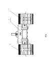
A kind of dismounting locomotive frame
Technical field
The utility model relates to a kind of vehicle frame, is specifically related to a kind of vehicle frame of removing machine.
Background technology
The dismounting machine belongs to special type engineering machinery, is generally used for the dismounting of building, and especially skyscraper can effectively be controlled the collapse direction that is removed thing under noiseless special operation condition, removes machineries with other and compares, and it has favorable environment protection and safety.Its working arm front end is equipped with sprinkler tip, can avoid stirring up a cloud of dust when removing the house, reduces surrounding resident, field activity person's dust infringement degree; Next is safety, adopts gas cutting to cause that easily fire is different with the construction of steel structure dismounting in the past, cuts the generation that dismounting has thoroughly prevented fire with hydraulic pressure, also can prevent the dispersion of falling object, guarantees construction safety.
The dismounting machine comprises chassis frame, be installed on turning gear, operator's compartment, equipment and hydraulic control device etc. on the chassis frame, working arm length in the described equipment is the operation height of dismounting machine, can be divided into 2 folding formulas, 3 folding formulas, 4 folding formulas dismounting machine, operation height is from tens meters to forties meters, to adapt to the dismounting operation of different story heights, the highest dismountable high-rise mansion more than 40 meters; Described chassis frame adopts the chassis of excavating machine mostly, the running gear that promptly has crawler belt, yet, improve constantly and remove continuing to increase of tonnage along with the operation height of removing machine, the chassis of dismounting machine also needs to strengthen thereupon, satisfies the job stabilization requirement of dismounting machine with this, and has so just brought great inconvenience to transportation, therefore need a kind of chassis frame that is specific to the dismounting machine, to adapt to the development of dismounting machine.
Summary of the invention
The utility model purpose provides a kind of dismounting locomotive frame of being convenient to transport.
For achieving the above object, the technical solution adopted in the utility model is: a kind of dismounting locomotive frame, comprise a vehicle frame body and be installed on traveling crawler on the vehicle frame body, described vehicle frame body comprises the left side that described traveling crawler is installed respectively, right walker, and connect left, the main car frame of right walker, a described left side, the opposite sides of right walker is respectively equipped with a pair of chute, the described main car frame at corresponding each described chute place is provided with outward extending, the pin that cooperates with chute, be provided with telescopic oil cylinder in each described pin, the outer end of its piston rod is fixed in the walker chute of respective side, described telescopic oil cylinder is connected with main pump through the oil circuit pipe, and its control end is connected with hydraulic control pump.
In the technique scheme, described dismounting machine comprises vehicle frame, turning gear, operator's compartment, equipment and hydraulic control device, the main effect of described vehicle frame is the walking of control dismounting machine and the weight of carrying complete machine, vehicle frame comprises a left side, right walker and main car frame, a left side, right walker is and ground contact portion, traveling crawler is installed on a left side respectively, on the right walker, turning gear, operator's compartment, equipment all is installed on the described main car frame, the left and right sides of main car frame is respectively equipped with outward extending pin, the pin cunning inserts in a left side, in the chute on the right walker, constitute shift sleeve structure, described telescopic oil cylinder is installed in the pin, by the slip of extension and contraction control pin in chute of piston rod; When the dismounting machine need betransported, oil cylinder shrank piston rod under the control of controller, and left and right walker is moved in opposite directions, shortened distance between the two, was convenient to transportation; When dismounting machine in working order the time, the hydraulic oil cylinder driving piston rod stretches out, and increases the distance of left and right sides walker, thereby increases the stability of complete machine.
In the technique scheme, described main car frame is H shape, the and arranged on left and right sides pin is sliding respectively to be inserted in the square hole chute on the walker of respective side, is respectively equipped with a locating dowel pin on the described left and right walker, and the inside and outside end of each described pin has the lockhole that cooperates with described locating dowel pin.When left and right driving frame launches, locating dowel pin inserts in the lockhole of cooresponding main car frame pin front end, and when needs shrink vehicle frame, locating dowel pin breaks away from lockhole, and after waiting to be retracted to the position, locating dowel pin inserts in the lockhole of pin rear end again and (can adopt electromagnet mode of the prior art (or other modes) to realize, electromagnet gets electric absorption locating dowel pin, make it break away from lockhole, after the dead electricity, locating dowel pin is inserted in the lockhole under the effect of retracing spring).
Because technique scheme utilization, the advantage that the utility model compared with prior art has is: because vehicle frame of the present utility model is divided into left walker, main car frame and right walker, main car frame inserts in a left side through the pin cunning, in the right walker, and by being installed on the telescopic oil cylinder control left side in the main car frame, stretching of right walker, contract, thereby when needs transport, vehicle frame can be shunk, shorten a left side, distance between right walker, be convenient to transportation, when in running order, extended vehicle frame increases a left side, distance between right walker adapts to the requirement of large-scale dismounting machine to chassis stability.
Description of drawings
Fig. 1 is the semi-sictional view structural representation of the utility model embodiment one;
Fig. 2 is the birds-eye view of Fig. 1;
Fig. 3 is the scheme drawing of the utility model embodiment one in working order the time;
Fig. 4 is the scheme drawing of the utility model embodiment one when travelling position;
Fig. 5 is that the local oil circuit pipe of the utility model embodiment one is arranged scheme drawing;
Fig. 6 is the running condition figure (equipment does not draw) of the utility model embodiment one.
Wherein: 1, main car frame; 2, left walker; 3, right walker; 4, chute; 5, pin; 6, telescopic oil cylinder; 7, piston rod; 8, oil circuit pipe; 9, locating dowel pin; 10, lockhole; 11, turning gear; 12, operator's compartment; 13, crawler belt; 14, vehicle frame body.
The specific embodiment
Below in conjunction with drawings and Examples the utility model is further described:
Embodiment one: extremely shown in Figure 6 referring to Fig. 1, a kind of dismounting locomotive frame, comprise a vehicle frame body 14 and be installed on traveling crawler 13 on the vehicle frame body, described vehicle frame body comprises the left walker 2 that is separately installed with described traveling crawler, right walker 3, and connect left, the main car frame 1 of right walker, a described left side, the opposite sides of right walker is respectively equipped with a pair of square hole chute 4, the described main car frame at corresponding each described chute place is provided with outward extending, the pin 5 that cooperates with chute, be provided with telescopic oil cylinder 6 in each described pin, the outer end of its piston rod 7 is fixed in the walker square hole chute of respective side, described telescopic oil cylinder is connected with main pump through oil circuit pipe 8, and its control end is connected with hydraulic control pump.
Referring to shown in Figure 2, described main car frame is H shape, the and arranged on left and right sides pin is sliding respectively to be inserted in the square hole chute on the walker of respective side, is respectively equipped with a locating dowel pin 9 on the described left and right walker, and the inside and outside end of each described pin has the lockhole 10 that cooperates with described locating dowel pin; When left and right driving frame launched, locating dowel pin inserted in the lockhole of cooresponding main car frame pin front end, and when needs shrank vehicle frame, locating dowel pin broke away from lockhole, and after waiting to be retracted to the position, locating dowel pin inserts in the lockhole of pin rear end again.
During use, as shown in Figure 6, the turning gear 11 of dismounting machine, operator's compartment 12, equipment all are installed on the main car frame, left and right walker contacts with ground, and the walking of machine and the weight of carrying complete machine are removed in major control, when the dismounting machine need betransported, 4 oil cylinders in the pin are controlled through hydraulic control pump, contraction is got up, and the distance of two walkers is shortened, and is convenient to transportation; When dismounting machine in working order the time, 4 oil cylinders will trail, and increase the distance of left and right sides walker, have so just increased the stability of complete machine.In the present embodiment, referring to Fig. 3,4, removing machine chassis frame two width of trackss when shrinking is 2390mm, can reach 3690mm when trailing.