CN201180875Y - Detachable connecting pipe fitting - Google Patents
Detachable connecting pipe fitting Download PDFInfo
- Publication number
- CN201180875Y CN201180875Y CNU2008200440834U CN200820044083U CN201180875Y CN 201180875 Y CN201180875 Y CN 201180875Y CN U2008200440834 U CNU2008200440834 U CN U2008200440834U CN 200820044083 U CN200820044083 U CN 200820044083U CN 201180875 Y CN201180875 Y CN 201180875Y
- Authority
- CN
- China
- Prior art keywords
- pipe fitting
- fittings
- connecting pipe
- clamp ring
- groove
- Prior art date
- Legal status (The legal status is an assumption and is not a legal conclusion. Google has not performed a legal analysis and makes no representation as to the accuracy of the status listed.)
- Expired - Fee Related
Links
Images
Abstract
The utility model is a detachable connecting pipe fitting applied to pipe networks, such as direct drinking water pipe networks of municipal, industrial and civil buildings, etc., for delivering pressure fluid. The connecting piece comprises an adapter body (1), a terminal nut (2) and a clamp ring (3), wherein inner holes are formed on the adapter body (1) and the terminal nut (2) along the longitudinal centerline and used for containing a pipe (6); a groove (21) is formed at one end of the terminal nut (2) and used for containing the clamp ring (3); the end part of the groove (21) is connected with the adapter body(1); and the clamp ring (3) is clamped in a hermetic cavity circled by the adapter body (1) and the groove (21) arranged on the terminal nut (2). Since the structure in which connecting pipes are pressed tightly through the clamp ring clamped between the adapter body and the terminal nut to generate plastic deformation is adopted, the connecting pipe fitting has the advantages of simple structure, quick and reliable connection between pipes which do not need to be processed, convenient field installation and disassembly, reutilization, good pressure bearing effect and sealing effect.
Description
Technical field:
The utility model is that a kind of pipe networks such as municipal administration, industry, civil building direct drinking water that are applied to carry out the detachable connecting pipe fitting that pressure fluid is carried, and particularly a kind of stainless steel detachable connecting pipe fitting belongs to the renovation technique of detachable connecting pipe fitting.
Background technique:
The Placement of existing pipe fitting has varied, and commonly used have clamp-press type, compression type, push type, welding type and a various derivation Placement, and these Placements respectively have its characteristics and applicable situation.The clamp-press type Placement is that pipe arrangement is inserted pipe fitting, the U type groove of pipe fitting two ends for protruding, built-in seal ring, needing with the special pipe fitting instrument socket joint position card to be compressed into row connects, the advantage of this Placement is sealing joint reliable performance, easy construction, and shortcoming is can not reuse after interface cost height, the dismounting; The advantage of welding manner is the sealing joint reliable performance, but its shortcoming is can not reuse after interface cost height, the dismounting, and construction is inconvenient; The screw thread of thread connecting mode is to make in the roll extrusion mode to form, and its advantage is that interface cost is low, can reuse after the dismounting, easy construction, but that its shortcoming is a sealability is reliable inadequately.More than various Placements all can not accomplish that under the sealability reliable premise interface cost is low.Thereby make the pipe-networks engineering cost high, cause thin walled tube, particularly promoting the use of of stainless-steel thin-wall pipe is restricted.
The model utility content:
The purpose of this utility model is to consider the problems referred to above and provides a kind of connection reliable, good airproof performance, and is easy to field erected detachable connecting pipe fitting.The utility model is processed and is constructed simple and convenient.
The technical solution of the utility model is: include fittings body, Female connector fittings, clamp ring, wherein fittings body, Female connector fittings longitudinally center line all make the endoporus that holds tubing respectively, and an end of Female connector fittings is made the groove that holds clamp ring, the end of groove is connected with fittings body, and the clamp ring mounting board is in the closed cavity that fittings body and the set groove of Female connector fittings are surrounded.
The outside thread that the end of the set groove of above-mentioned Female connector fittings is made by the internal thread made on it and fittings body end spins.
Make the shoulder of the mounting point of fastening tubing on the inwall of above-mentioned fittings body.
The surface of contact of above-mentioned clamp ring and the set groove of Female connector fittings is last convex surface.
The shoulder and the surface of contact between the tubing of above-mentioned fittings body are provided with first seal ring.
The inwall and the surface of contact between the tubing of above-mentioned fittings body are provided with second seal ring.
The inwall of above-mentioned fittings body is made the groove that embeds second seal ring.
The utility model is owing to adopt the clamp ring by being clipped between fittings body and the Female connector fittings to produce the structure that plastic deformation compresses connection tubing, therefore, the utility model is simple in structure, tubing need not to carry out any processing, can realize quick between the pipe fitting, connection reliably, on-the-spot installation and removal are very convenient, and recyclable, and good pressure-bearing effect and sealing effect are arranged.The utility model is a kind of convenient and practical detachable connecting pipe fitting.
Description of drawings:
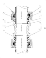
Fig. 1 is a structural representation of the present utility model.
Embodiment:
Embodiment:
Structural representation of the present utility model as shown in Figure 1, include fittings body 1, Female connector fittings 2, clamp ring 3, wherein fittings body 1, Female connector fittings 2 longitudinally center line all make the endoporus that holds tubing 6 respectively, and an end of Female connector fittings 2 is made the groove 21 that holds clamp ring 3, the end of groove 21 is connected with fittings body 1, and clamp ring 3 mounting boards are in the closed cavity that fittings body 1 and Female connector fittings 2 set grooves 21 are surrounded.
In the present embodiment, for ease of processing and install, the outside thread that the end of above-mentioned Female connector fittings 2 set grooves 21 is made by the internal thread made on it and fittings body 1 end spins.
For ease of determining the mounting point of tubing 6, make the shoulder 11 of the mounting point of fastening tubing 6 on the inwall of above-mentioned fittings body 1.
Can produce the active force that acts in the clamp ring 3 when guaranteeing that Female connector fittings 2 is connected with fittings body 1, so that clamp ring 3 produces plastic deformation on direction perpendicular to axial direction and embedding is pressed into tubing 6, above-mentioned clamp ring 3 is last convex surface with the surface of contact 31 of Female connector fittings 2 set grooves 21.
For guaranteeing sealing, the shoulder 11 and the surface of contact between the tubing 6 of above-mentioned fittings body 1 are provided with first seal ring 5.Surface of contact between the inwall of above-mentioned fittings body 1 and the tubing 6 is provided with second seal ring 4.For ease of installing, the inwall of above-mentioned fittings body 1 is made the groove 12 that embeds second seal ring 4.
When the utility model engages in construction, fittings body 1 and Female connector fittings 2 are by being threaded togather, and in the tension process, clamp ring 3 produces plastic deformation on direction perpendicular to axial direction and embedding is pressed into tubing 6, form the firm engagement of pipe fitting and tubing, and produce good seal action.And when needs separate the pipe fitting dismounting, only need Female connector fittings 2 reverse back-outs are got final product, it is very convenient to adorn folding.
Claims (7)
1, a kind of detachable connecting pipe fitting, it is characterized in that including fittings body (1), Female connector fittings (2), clamp ring (3), wherein fittings body (1), Female connector fittings (2) longitudinally center line all make the endoporus that holds tubing (6) respectively, and an end of Female connector fittings (2) is made the groove (21) that holds clamp ring (3), the end of groove (21) is connected with fittings body (1), and clamp ring (3) mounting board is in the closed cavity that fittings body (1) and the set groove of Female connector fittings (2) (21) are surrounded.
2, detachable connecting pipe fitting according to claim 1, the outside thread that the end that it is characterized in that the set groove of above-mentioned Female connector fittings (2) (21) is made by the internal thread made on it and fittings body (1) end spins.
3, detachable connecting pipe fitting according to claim 1 is characterized in that making on the inwall of above-mentioned fittings body (1) shoulder (11) of the mounting point of fastening tubing (6).
4, detachable connecting pipe fitting according to claim 1 is characterized in that the above-mentioned clamp ring (3) and the surface of contact (31) of the set groove of Female connector fittings (2) (21) are last convex surface.
5,, it is characterized in that the shoulder (11) of above-mentioned fittings body (1) and the surface of contact between the tubing (6) are provided with first seal ring (5) according to each described detachable connecting pipe fitting of claim 1 to 4.
6, detachable connecting pipe fitting according to claim 5 is characterized in that the inwall of above-mentioned fittings body (1) and the surface of contact between the tubing (6) are provided with second seal ring (4).
7, detachable connecting pipe fitting according to claim 6 is characterized in that the inwall of above-mentioned fittings body (1) is made the groove (12) that embeds second seal ring (4).
Priority Applications (1)
| Application Number | Priority Date | Filing Date | Title |
|---|---|---|---|
| CNU2008200440834U CN201180875Y (en) | 2008-02-18 | 2008-02-18 | Detachable connecting pipe fitting |
Applications Claiming Priority (1)
| Application Number | Priority Date | Filing Date | Title |
|---|---|---|---|
| CNU2008200440834U CN201180875Y (en) | 2008-02-18 | 2008-02-18 | Detachable connecting pipe fitting |
Publications (1)
| Publication Number | Publication Date |
|---|---|
| CN201180875Y true CN201180875Y (en) | 2009-01-14 |
Family
ID=40250376
Family Applications (1)
| Application Number | Title | Priority Date | Filing Date |
|---|---|---|---|
| CNU2008200440834U Expired - Fee Related CN201180875Y (en) | 2008-02-18 | 2008-02-18 | Detachable connecting pipe fitting |
Country Status (1)
| Country | Link |
|---|---|
| CN (1) | CN201180875Y (en) |
Cited By (4)
| Publication number | Priority date | Publication date | Assignee | Title |
|---|---|---|---|---|
| CN101307846B (en) * | 2008-02-18 | 2012-06-27 | 吴百海 | Detachable connecting pipe fitting |
| CN106402529A (en) * | 2016-09-29 | 2017-02-15 | 大连民族大学 | Quick connecting device for rigid straight pipe parts under vacuum environment |
| CN106764150A (en) * | 2017-03-27 | 2017-05-31 | 戴爱清 | Snap ring locking type pipeline connecting assemble |
| CN108591644A (en) * | 2018-06-12 | 2018-09-28 | 海盐六里液压管件有限公司 | A kind of reusable locking pipe fitting |
-
2008
- 2008-02-18 CN CNU2008200440834U patent/CN201180875Y/en not_active Expired - Fee Related
Cited By (4)
| Publication number | Priority date | Publication date | Assignee | Title |
|---|---|---|---|---|
| CN101307846B (en) * | 2008-02-18 | 2012-06-27 | 吴百海 | Detachable connecting pipe fitting |
| CN106402529A (en) * | 2016-09-29 | 2017-02-15 | 大连民族大学 | Quick connecting device for rigid straight pipe parts under vacuum environment |
| CN106764150A (en) * | 2017-03-27 | 2017-05-31 | 戴爱清 | Snap ring locking type pipeline connecting assemble |
| CN108591644A (en) * | 2018-06-12 | 2018-09-28 | 海盐六里液压管件有限公司 | A kind of reusable locking pipe fitting |
Similar Documents
| Publication | Publication Date | Title |
|---|---|---|
| CN101307846B (en) | Detachable connecting pipe fitting | |
| CN201116634Y (en) | Conical surface O-shaped ring sealing type pipeline mobile joint | |
| CN201180876Y (en) | Collapsible connector | |
| CN201180875Y (en) | Detachable connecting pipe fitting | |
| CN201074712Y (en) | Leak-proof quick joint for pipe | |
| CN207584216U (en) | A kind of ferrule-type compression joint with inner card cage | |
| CN203297796U (en) | Pipeline connecting device | |
| CN201273426Y (en) | Large-diameter glass fiber reinforced epoxy plastics pipe connector | |
| CN201858454U (en) | Splicing pipe connecting pipe fitting with bushing | |
| CN204163819U (en) | Exhaust pipe connection structure and there is the automobile exhaust pipe assembly of this structure | |
| CN103591402A (en) | Novel two-ferrule tube fitting | |
| CN2918944Y (en) | Screw-threaded pipe joint | |
| CN2615475Y (en) | Hose sealing connector | |
| CN101561063A (en) | Ferrule type pipe connector | |
| CN202577554U (en) | Polypropylene mute drainpipe fitting provided with double buckle type threaded connection head | |
| CN203431342U (en) | Movable joint used for building gas aluminum plastic composite tube | |
| CN201180873Y (en) | Thin walled pipe connector | |
| CN201297467Y (en) | Quick plug pipeline joint | |
| CN100526699C (en) | Sealed joint of separated assembled fluid pipeline | |
| CN102454841A (en) | Inserted connecting pipe fitting with bushing | |
| CN203147105U (en) | Novel attachment joint | |
| CN212776069U (en) | Novel sealing pipe fitting | |
| CN215721445U (en) | Anti-blocking pipeline connector structure | |
| CN201827563U (en) | High-pressure quick pipe joint | |
| CN211289129U (en) | Quick plug-in metal pipeline connecting device that can seal in advance |
Legal Events
| Date | Code | Title | Description |
|---|---|---|---|
| C14 | Grant of patent or utility model | ||
| GR01 | Patent grant | ||
| C17 | Cessation of patent right | ||
| CF01 | Termination of patent right due to non-payment of annual fee |
Granted publication date: 20090114 Termination date: 20100218 |