CN201147916Y - Box for fastening tools - Google Patents
Box for fastening tools Download PDFInfo
- Publication number
- CN201147916Y CN201147916Y CN200720177423.6U CN200720177423U CN201147916Y CN 201147916 Y CN201147916 Y CN 201147916Y CN 200720177423 U CN200720177423 U CN 200720177423U CN 201147916 Y CN201147916 Y CN 201147916Y
- Authority
- CN
- China
- Prior art keywords
- magazine
- slide block
- support member
- internal guide
- guide rail
- Prior art date
- Legal status (The legal status is an assumption and is not a legal conclusion. Google has not performed a legal analysis and makes no representation as to the accuracy of the status listed.)
- Expired - Fee Related
Links
Images


Classifications
-
- B—PERFORMING OPERATIONS; TRANSPORTING
- B25—HAND TOOLS; PORTABLE POWER-DRIVEN TOOLS; MANIPULATORS
- B25C—HAND-HELD NAILING OR STAPLING TOOLS; MANUALLY OPERATED PORTABLE STAPLING TOOLS
- B25C1/00—Hand-held nailing tools; Nail feeding devices
- B25C1/001—Nail feeding devices
- B25C1/005—Nail feeding devices for rows of contiguous nails
-
- B—PERFORMING OPERATIONS; TRANSPORTING
- B25—HAND TOOLS; PORTABLE POWER-DRIVEN TOOLS; MANIPULATORS
- B25C—HAND-HELD NAILING OR STAPLING TOOLS; MANUALLY OPERATED PORTABLE STAPLING TOOLS
- B25C5/00—Manually operated portable stapling tools; Hand-held power-operated stapling tools; Staple feeding devices therefor
- B25C5/16—Staple-feeding devices, e.g. with feeding means, supports for staples or accessories concerning feeding devices
- B25C5/1606—Feeding means
- B25C5/1617—Feeding means employing a spring-loaded pusher
-
- Y—GENERAL TAGGING OF NEW TECHNOLOGICAL DEVELOPMENTS; GENERAL TAGGING OF CROSS-SECTIONAL TECHNOLOGIES SPANNING OVER SEVERAL SECTIONS OF THE IPC; TECHNICAL SUBJECTS COVERED BY FORMER USPC CROSS-REFERENCE ART COLLECTIONS [XRACs] AND DIGESTS
- Y10—TECHNICAL SUBJECTS COVERED BY FORMER USPC
- Y10T—TECHNICAL SUBJECTS COVERED BY FORMER US CLASSIFICATION
- Y10T29/00—Metal working
- Y10T29/49—Method of mechanical manufacture
- Y10T29/49826—Assembling or joining
Abstract
The utility model relates to a box used for a tightening device. The tightening device drives one or a plurality of fasteners into workpieces. The box comprises an external box body and an internal guide way. The internal guide way can move relative to the external box body. The internal guide way extends from the external box body so that the one or plurality of fasteners can be filled in the box. A bar extends between the front end and the back end. A push support member glides and receives the bar. The spring presses the push support member towards the front end. A push slipper is connected with the push support member. The push slipper moves along the internal guide way, and can be operated so that the one or plurality of fasteners move toward the front end. The push slipper can move relative to the push support member.
Description
Technical field
The present invention relates to a kind of fastened tools, promotion support member in being specifically related to and promotion slide block, distribute stress on its more uniform one or more securing members in magazine.
Background technology
Developed multiple pneumatic and electrically operated instrument to driving securing member, for example bail and nail are fastened in the workpiece.Usually, these instruments adopt magazine, are used to keep a plurality of securing members and before the driving securing member enters in the workpiece, transmit securing member in the head of instrument.
Although this class instrument is widely used, the known securing member of presenting and enter the driving sword groove that forms in the fastened tools head by magazine may block.In this, the acceptable tolerance of the whole parts of magazine is added up, and adds the flaw of securing member, has increased the obstruction of the securing member in the magazine.Though the securing member that blocks can be discharged from magazine and head easily, still has improved space in this area.
Summary of the invention
In order to solve above-mentioned the problems of the prior art, the various aspects of this explanation instruction generally include the magazine that is used for fastened tools, and its of driving and a plurality of securing members enter in the workpiece.Magazine comprises external shell and internal guide rail, and internal guide rail is movably with respect to external box of microvave.Internal guide rail extends so that allow from external box of microvave magazine is increased by one and a plurality of securing members.Between the front-end and back-end of internal guide rail, extend a bar.Promote support member and hold this rule slidably.The spring bias voltage promotes support member towards front end.Promoting slide block engages with the promotion support member.Promoting slide block is movably along internal guide rail, and operationally makes one or more securing members towards front end.Promoting slide block is movably with respect to promoting support member.
Because described promotion support member can be actuated towards the frame head and be promoted slide block and securing member, thus promote slide block operationally with respect to or move or shake about promoting support member.Owing to the promotion slide block can move about the promotion support member, to compare so be rigidly connected to other the suitable situation partly that promotes support member or magazine with the promotion slide block, the pressure that is applied to securing member by the promotion slide block can be more even.
Further suitable application area will be apparent from description given below.Be understandable that specification and embodiment only are used for illustration purpose, limit the scope of the invention and be not used in.
Description of drawings
The description of drawings here only is used for illustration purpose, and the scope that does not limit the present invention in any way.
Fig. 1 is the schematic diagram of fastened tools constructed according to the invention, and it illustrates frame head and magazine in the closed position.The frame head is shown against workpiece, makes contact trip mechanism be in retracted state;
The similar Fig. 1 of Fig. 2 also illustrates the magazine that is shown in an open position, and shown in the frame head do not engage.By the termination of unassembled head, contact trip mechanism is in extended configuration, and the fastened tools assembly that can not be triggered activates;
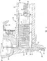
The similar Fig. 2 of Fig. 3 also illustrates triggering assembly, depth adjustment mechanism and magazine folder;
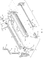
Fig. 4 is the exploded view of magazine shown in Figure 1, external box of microvave, internal guide rail, promotion slide block is shown and promotes support member;
Fig. 5 is the partial cross section figure of Fig. 1, illustrates and promotes support member, promotes the securing member in slide block and the magazine, and described magazine has the external box of microvave that cuts as shown in the figure;
Fig. 6 is the partial cross section figure that is different from Fig. 1, illustrates to drive the sword groove, and its outside head element and inner head element by the frame head forms.Inner head is connected in magazine, and it is in the closed position;
Fig. 7 schematic diagram illustrate promote slide block the promotion surface slightly upward to being abutted against last securing member can shake about promoting support member owing to promote slide block, promote support member and instruct according to the present invention and construct;
The similar Fig. 7 of Fig. 8 illustrates with respect to promoting support member and is in downward slightly promotion slide block, and described promotion support member is instructed according to the present invention and constructed.
The specific embodiment
Following description only is schematically, and is not used in restriction instruction of the present invention, its application or use.Be appreciated that respective digital refers to identical or appropriate section and feature in whole accompanying drawings.
About Fig. 1 and Fig. 2, this explanation comprises fastened tools 10 substantially, and it has main housing 12, and this housing can comprise driving mechanism 14, and described driving mechanism is used to drive one or more securing member 16, for example nail or staple.Fastened tools 10 can comprise handle 18, frame head 20 and magazine 22, and the layout of frame head 20 can be lower than main casing 12, and magazine 22 can be connected in frame head 20 and handle 18.Triggering assembly 24 can be arranged on the main casing 12 and/or on the handle 18, be used to activate driving mechanism 14, as known in the art.Driving mechanism 14 can comprise, for example, based on pneumatic system, the conventional design in for example common United States Patent (USP) of transferring the possession of 3673922 or 5181450, or the electrical system in the United States Patent (USP) 4928868.The above-mentioned content that relates to is all included by reference at this.
About Fig. 5 and Fig. 6, magazine 22 can comprise securing member 16, and can continuously securing member 16 be supplied in the driving sword groove 26.Drive in the sword groove 26 in case securing member 16 is arranged in, driving sword 28 can stretch from retracted state (Fig. 1), detaches from drive sword groove 26 so that drive a securing member 16, and enters in the workpiece 30 (Fig. 1).When driving mechanism 14 activates by triggering assembly 24, drive sword 28 and can be stretched over an extended configuration, as known in the art from retracted state.
About accompanying drawing 4, Fig. 7 and Fig. 8, magazine 22 can comprise promotion support member 32, and it can make and be positioned at the promotion surface 34 promotion securing members 16 that promote on the slide block 36, so that make securing member 16 towards frame head 20.Can move with respect to promoting support member 32 owing to promote slide block 36, as can be seen, when promotion slide block 36 makes securing member 16 towards frame head 20, promote slide block 36 and can provide more uniform relatively pressure for securing member 16.Because promoting slide block 36 can move or shake about promoting support member 32, so promoting the promotion surface 34 of slide block 36 can be with respect to promoting support member 32, catch bar or promoting bar 38, be arranged in nonparallel direction, wherein promote support member 32 and on the promotion bar, slide.Can be adjacent to securing member 16 owing to promote surface 34, this direction is not parallel to the direction that opposing promotes slide block 36 stress applications, as can be seen, with respect to the promotion slide block that can in described magazine, move, the tendency that securing member 16 is blocked in the magazine 22 can reduce, and for described promotion slide block other suitable situations that partly can not move or shake with respect to catch bar or magazine 22, then opposite.
About Fig. 3, Fig. 4 and Fig. 6, contact trip mechanism 42 can comprise bottom end member 40.Bottom end member 40 can have first 44, and first 44 is linked together with frame head 20, and first 44 can engage with termination 46, and termination 46 can contact with workpiece 30 (Fig. 1).The second portion 48 of bottom end member 40 can engage with depth adjustment mechanism 50, and depth adjustment mechanism 50 is arranged in and triggers below the assembly 24.When termination 46 pressurizeds opposing workpiece 30, as shown in Figure 1, contact trip mechanism 42 can move to retracted state by extended configuration.When contact trip mechanism 42 was in retracted state, contact trip mechanism 42 can allow the driving mechanism 14 of fastened tools 10, was activated by triggering assembly 24, as known in the art.When contact trip mechanism 42 was in extended configuration, fastened tools 10 can not be activated.
About Fig. 3 and Fig. 5, magazine 22 comprises external box of microvave 56, and wherein internal guide rail 58 can slide into closed position (Fig. 1) by open position (Fig. 3).At open position, one or more securing members 16 can add magazine 22 to, though in this position, wherein internal guide rail 58 is more farther than shown in Figure 3 from moving of frame head 20.Internal guide rail 58 can be closed then,, moves to the closed position that is, as shown in Figure 1, so that make securing member 16 opposing frame heads 20, and arranges one of a plurality of securing members 16 that are positioned at driving sword groove 26 thus, as shown in Figure 6.
Described promotion slide block is the U type substantially, and is inverted on the described internal guide rail, and described promotion slide block 36 can be positioned at the inverted U structure, and frame is on the crown member 60 of internal guide rail 58.Like this, promote surface 34 and can determine that wall 62 connects by the top section 64 that promotes slide block 36 by a pair of wall 62.Promote the layout on surface 34 and can be substantially match with the direction of securing member 16, for example, staple 66 (that is, last staple) surface is adjacent to and promotes surface 34, wherein staple 66 and promote surperficial 34 parallel fully, as shown in Figure 7 and Figure 8.
Promoting slide block 36 can be made of acetal (acetal), and it can be polyacetals, polyformaldehyde usually.Other condensate that is fit to can be used to form equally and promote slide block 36.For example, promoting slide block can be by the Delrin of DuPont company
 Or Ticona (Florence, KY) Celcon of company
 Make.
Make.
When promoting slide block 36 and make by acetal or other appropriate materials, promote slide block 36 and have coefficient of friction, it is less than or equal to the coefficient of friction of internal guide rail 58, and/or promotes the coefficient of friction that slide block 36 externally slides on the casing 56.Internal guide rail 58 and external box of microvave 56 can be made by aluminium or other suitable metal or plastics.Promote the ability of slide block 36, can reduce securing member 16 tendency of in magazine 22, being obstructed along internal guide rail 58 easier slips.
When internal guide rail 58 moves to the closed position (Fig. 1), inner head element 72 approaches to belong to equally the outside head element 76 of frame head 20, but can be still with outside head element 76 separately.This is the interval between head element 76 and the inner head element 72 externally, can enough limit to drive sword groove 26 (that is, when a securing member 16 be driven the groove that passes through when being moved into workpiece 30).In addition, securing member 16 can be resisted the surface of outside head element 76, and this surface can be towards driving sword groove 26, and one of arrangement securing member 16 in driving sword groove 26 thus, as shown in Figure 5.
Promote support member 32 and can be formed with through hole 84, through hole 84 receives catch bar 38 slidably.In addition, spring 86 can be arranged on the catch bar 38, so that catch bar 38 screw threads are by spring 86.Spring 86 can engage with promoting support member 32, promotes support member 32 towards frame head 20 bias voltages so that make.Promote support member 32 can, conversely, and promote slide block 36 and engage.
Promote slide block 36 and can determine a pair of circular hole 88, circular hole 88 is formed in each wall 62, and it is configured to hold promotion support member 32.Promote support member 32 and can have circle or semicolumn structure (Fig. 4) equally, it can be contained in the hole 88 of the wall 62 that promotes slide block 36.Like this, ball-and-socket cooperates 90 can be formed between promotion support member 32 and the promotion slide block 36.Promote slider bore 88 and can allow, when promotion support member 32 makes promotion slide block 36, securing member 16 towards frame head 20, promote slide block 36 and move (that is, pivoting) with respect to promotion support member 32 with the circular structure that promotes support member 32.
Promote support member 32 and can have wall 92, it can be parallel to each other substantially.Promote support member 32 and have general cylindrical surface 94 equally, it can be limited by wall 92.Dotted line 96 can be along extending perpendicular to cylindrical surface 94 substantially.Dotted line 96 can be equally substantially perpendicular to dotted line 98, and dotted line 98 can extend from a wall 92.The wall 62 that promotes slide block can flush substantially in the wall 92 that promotes support member 32.Thus, the hole 88 that promotes slide block can have curved surface 100, and it can hold the cylindrical surface 94 that promotes support member 32.Thus, make when promoting slide block 36 and securing member 16 towards frame head 20 when promoting support member 32, promote slide block 36 can operate with respect to move and shake about promoting support member 32.
For example,, put on the power of first direction 102 by spring 86 about Fig. 7 and Fig. 8, can, conversely, put on staple 66 in second direction 104 by promoting surface 34.First direction 102 and second direction 104, some the time, and not parallel, and second direction 104 does not need to be parallel to catch bar 38.Can move about promoting support member 32 owing to promoting slide block 36, invest the promotion support member rigidly with the promotion slide block and compare with the situation of other suitable part in the magazine, the pressure that puts on securing member 16 by promotion slide block 36 can be more even.
About Fig. 3, magazine 22 can engage at first tie point 106 and second tie point 108 with main casing 12 and/or handle 18.First tie point 106 can be adjacent to frame head 20, so that the front end 110 of magazine 22 can engage with frame head 20, drives sword groove 26 so that form betwixt.At second tie point 108, magazine 22 is connected in the rear end 112 of handle 18.
At second tie point 108, housing 12 can comprise magazine folder 114.Magazine folder 114 (Fig. 4) can pivot on pin 116, sell 116 and engage with handle 18.In addition, spring 118 can make magazine folder 114 bias voltage in latched position, as shown in Figure 1.By push magazine folder 114 towards the bias voltage of housing 12 and antagonistic spring 118, magazine folder 114 can move to non-locked position by latched position.Because magazine folder 114 is positioned at non-locked position, internal guide rail 58 can be extracted out by the external box of microvave 56 of magazine 22, and is pulled away from frame head 20, as shown in Figure 3.By pulling out internal guide rail 58 and away from frame head 20, securing member 16 can add magazine 22 to, so that replenish the securing member 16 in the magazine 22.
When securing member 16 added magazine 22 to, internal guide rail 58 can turn back to the closed position, as shown in Figure 1.Magazine buffer 74 can be connected in internal guide rail 58, and magazine buffer 74 can press from both sides 114 with magazine and engage, so that keep magazine 22 in the closed position, as shown in Figure 1.
About Fig. 6, Fig. 7 and Fig. 8, when one or more securing members 16 are contained in the magazine 22, promote slide block 36 securing member (for example, staple 66) to the end of must conflicting, last securing member is contained in the magazine 22 with respect to frame head 20.To promote to be compressed (Fig. 3) between support member 32 and the magazine buffer 74 at the spring on the catch bar 38 86, and make thus promote support member 32 at first direction towards frame head 20 bias voltages.Be applied to the stress transfer that promotes on the slide block 36 to securing member 16, make securing member 16 distribute securing members to driving in the sword groove 26 thus towards frame head 20.Can move for promoting support member 32 owing to promote slide block 36, promoting surface 34 can be at 104 pairs of securing member 16 stress application of second direction, and second direction is not parallel to first direction 102.In addition, promoting slide block 36 can shake for promoting support member 32, so that second direction 104 can form acute angle up and/or down about first direction, as shown in Figure 7 and Figure 8.
When the description and shown in the drawings in specification of concrete aspect, it will be understood by those skilled in the art that under the situation that does not deviate from the scope of the invention as claimed in claim, can carry out multiple variation, and the parts that equate can be replaced therein.In addition, the mixing of the feature of different aspect of the present invention, element and/or function also cooperates and can clearly be expected, so that it will be understood by those skilled in the art that feature, element and/or the function of one aspect of the invention can be combined on the other hand, unless top have description in addition.In addition, in the case without departing from the scope of the present invention, can carry out more modifications to adapt to particular case, structure or the material of the present invention's instruction.Thus, mean, the invention is not restricted to that as the described special aspects of realization optimum embodiment of the present invention, but scope of the present invention will comprise foregoing description and subsidiary interior multiple aspect and the embodiment of claim by in the drawing and description.
Claims (9)
1. magazine that is used for fastened tools, this fastened tools drives one or more securing members in workpiece, it is characterized in that, and this magazine comprises:
External box of microvave and internal guide rail, this internal guide rail is movably with respect to described external box of microvave, described internal guide rail can stretch out from described external box of microvave, adds one or more securing members so that allow to magazine;
The bar that between described internal guide rail front-end and back-end, extends;
Slidably receive described promotion support member;
Spring is towards the described promotion support member of described front end bias voltage; And
Promote slide block, it is engaged in described promotion support member, and described promotion slide block can move along described internal guide rail, and in order to force described one or more securing member towards described front end, wherein said promotion slide block can move around described promotion support member.
2. magazine as claimed in claim 1 is characterized in that, described promotion slide block is made by polymer, and the coefficient of friction of described polymer is less than the coefficient of friction of described internal guide rail and described external box of microvave.
3. magazine as claimed in claim 1 is characterized in that, described promotion support member and described promotion slide block form ball-and-socket joint.
4. magazine as claimed in claim 1 is characterized in that, described promotion slide block can apply power in the direction that is not parallel to described to described one or more securing members.
5. magazine as claimed in claim 1 is characterized in that, described promotion slide block is the U type substantially, and is inverted on the described internal guide rail.
6. magazine as claimed in claim 1 is characterized in that, inner head element extends from the described front end of described internal guide rail, and the outside head element of described inner head element and frame head determines to drive the sword groove betwixt.
7. magazine as claimed in claim 1, it is characterized in that, described promotion support member comprises two walls that are parallel to each other substantially, with the periphery of delimiting by described two walls basically, the wherein imaginary line that hangs down substantially and extend along the imaginary line that extends perpendicular to described periphery direction as for from one of described two walls.
8. magazine as claimed in claim 7 is characterized in that, described promotion slide block comprise a pair of substantially with described two walls that wall is mutually concordant of described promotion support member.
9. magazine as claimed in claim 7 is characterized in that, described promotion slide block comprises a pair of wall, and curved basically hole is formed on each described wall, makes the periphery of the described curved basically described promotion support member of hole breasting.
Applications Claiming Priority (2)
| Application Number | Priority Date | Filing Date | Title |
|---|---|---|---|
| US11/493,995 US7284685B1 (en) | 2006-07-27 | 2006-07-27 | Pusher bearing and pusher block for magazine feeder |
| US11/493,995 | 2006-07-27 |
Publications (1)
| Publication Number | Publication Date |
|---|---|
| CN201147916Y true CN201147916Y (en) | 2008-11-12 |
Family
ID=38566036
Family Applications (1)
| Application Number | Title | Priority Date | Filing Date |
|---|---|---|---|
| CN200720177423.6U Expired - Fee Related CN201147916Y (en) | 2006-07-27 | 2007-07-27 | Box for fastening tools |
Country Status (5)
| Country | Link |
|---|---|
| US (3) | US7284685B1 (en) |
| EP (1) | EP1882557B1 (en) |
| CN (1) | CN201147916Y (en) |
| AT (1) | ATE462535T1 (en) |
| DE (1) | DE602007005550D1 (en) |
Families Citing this family (36)
| Publication number | Priority date | Publication date | Assignee | Title |
|---|---|---|---|---|
| US7284685B1 (en) * | 2006-07-27 | 2007-10-23 | Black & Decker Inc. | Pusher bearing and pusher block for magazine feeder |
| US7413105B1 (en) * | 2007-03-22 | 2008-08-19 | Apach Industrial Co., Ltd. | Pushing device of drawer type magazine for nail gun |
| US8376204B2 (en) * | 2007-05-04 | 2013-02-19 | Illinois Tool Works Inc. | Side load magazine for a fastener drivers |
| CN201061875Y (en) * | 2007-05-29 | 2008-05-21 | 车王电子股份有限公司 | Nail box for both U-shaped nail and T-shaped nail |
| US8899460B2 (en) * | 2007-06-12 | 2014-12-02 | Black & Decker Inc. | Magazine assembly for nailer |
| JP5125842B2 (en) * | 2008-07-18 | 2013-01-23 | マックス株式会社 | Stapling nailer |
| US8292144B2 (en) * | 2009-07-13 | 2012-10-23 | Laboratoire Primatech Inc. | Nailer with controlled action feeder magazine assembly |
| US8833626B2 (en) | 2010-09-29 | 2014-09-16 | Stanley Fastening Systems, L.P. | Fastening tool |
| TW201218909A (en) * | 2010-10-29 | 2012-05-01 | Hon Hai Prec Ind Co Ltd | Container data center |
| US20130153620A1 (en) * | 2011-12-16 | 2013-06-20 | Roger Shen | Staple Gun |
| CN203566643U (en) * | 2013-11-21 | 2014-04-30 | 浙江荣鹏气动工具有限公司 | Quick-release three-in-one pneumatic toenail gun |
| USD756740S1 (en) | 2014-06-02 | 2016-05-24 | Stanley Fastening Systems, L.P. | Pneumatic nailer |
| USD756739S1 (en) | 2014-06-02 | 2016-05-24 | Stanley Fastening Systems, L.P. | Pneumatic nailer |
| CN104118716B (en) * | 2014-07-22 | 2016-09-14 | 广东明晖气动科技有限公司 | Nailing machine is with warehouse style nail frame |
| US11808049B2 (en) * | 2015-01-14 | 2023-11-07 | Luther Sivadjian | Rebar joint tie tool |
| CN208289826U (en) | 2015-02-06 | 2018-12-28 | 米沃奇电动工具公司 | Using gas spring as the fastener driver of power |
| US10814465B2 (en) | 2016-03-22 | 2020-10-27 | Stanley Black & Decker, Inc. | Safety device for tackers |
| US11325235B2 (en) | 2016-06-28 | 2022-05-10 | Black & Decker, Inc. | Push-on support member for fastening tools |
| US11267114B2 (en) | 2016-06-29 | 2022-03-08 | Black & Decker, Inc. | Single-motion magazine retention for fastening tools |
| US11279013B2 (en) | 2016-06-30 | 2022-03-22 | Black & Decker, Inc. | Driver rebound plate for a fastening tool |
| US11400572B2 (en) | 2016-06-30 | 2022-08-02 | Black & Decker, Inc. | Dry-fire bypass for a fastening tool |
| US10987790B2 (en) | 2016-06-30 | 2021-04-27 | Black & Decker Inc. | Cordless concrete nailer with improved power take-off mechanism |
| USD873105S1 (en) * | 2016-11-07 | 2020-01-21 | Black & Decker, Inc. | Cordless nailer |
| US10926385B2 (en) * | 2017-02-24 | 2021-02-23 | Black & Decker, Inc. | Contact trip having magnetic filter |
| USD852015S1 (en) * | 2017-08-16 | 2019-06-25 | Black & Decker, Inc. | Cordless nailer |
| USD852014S1 (en) * | 2017-08-16 | 2019-06-25 | Black & Decker, Inc. | Cordless nailer |
| TWI619583B (en) * | 2017-10-24 | 2018-04-01 | 金鉅準工業股份有限公司 | Nail magazine with a width-adjustable nail-receiving space |
| CN109877783A (en) * | 2019-01-18 | 2019-06-14 | 杭州新星光电有限公司 | Nailing device and ailing machine comprising the nailing device |
| USD901274S1 (en) * | 2019-04-24 | 2020-11-10 | Black & Decker, Inc. | Cordless stapler |
| USD909841S1 (en) * | 2019-11-08 | 2021-02-09 | Robert Bosch Power Tools GmbH | Power tool |
| USD912488S1 (en) * | 2019-12-10 | 2021-03-09 | Black & Decker, Inc. | Cordless nailer |
| USD962032S1 (en) * | 2019-12-26 | 2022-08-30 | Zhejiang Prulde Electric Appliance Co., Ltd. | Nail gun |
| EP4126460A4 (en) | 2020-03-27 | 2023-12-06 | Milwaukee Electric Tool Corporation | Powered fastener driver |
| WO2021202723A1 (en) * | 2020-03-31 | 2021-10-07 | Milwaukee Electric Tool Corporation | Powered fastener driver |
| KR102206400B1 (en) * | 2020-11-12 | 2021-01-22 | 이영훈 | Apparatus for fixing pin construction of pipe |
| CN112440352B (en) * | 2020-11-24 | 2022-04-01 | 广州华新科智造技术有限公司 | Code nail adding assembly and code nail printing device |
Family Cites Families (29)
| Publication number | Priority date | Publication date | Assignee | Title |
|---|---|---|---|---|
| US3820705A (en) | 1972-08-07 | 1974-06-28 | W Beals | Nailing machine |
| DE8316035U1 (en) * | 1983-06-01 | 1983-10-20 | Black & Decker, Inc. (eine Gesellschaft n.d.Ges.d. Staates Delaware), 19711 Newark, Del. | CLAMP MAGAZINE FOR A MANUAL OR MOTOR DRIVEN CLAMP |
| US4524896A (en) * | 1983-10-31 | 1985-06-25 | Senco Products, Inc. | Reversible staple feeder shoe and door system for the magazine of a staple driving tool |
| US5163596A (en) * | 1990-11-08 | 1992-11-17 | Fastech, Inc. | Portable pneumatic tool employing improved magazine feed, eject and jam-clearing technique |
| JPH04365567A (en) * | 1991-06-12 | 1992-12-17 | Makita Corp | Pusher device for nail driver |
| JP3272750B2 (en) * | 1991-09-21 | 2002-04-08 | 株式会社マキタ | Nail guide device for nailing machine |
| EP1658942B1 (en) * | 1999-03-04 | 2007-05-30 | Max Co., Ltd. | Magazine mechanism for nailing machine |
| US6173877B1 (en) * | 1999-11-05 | 2001-01-16 | Arrow Fastener Co., Inc. | Nail magazine for a power nailer |
| US6398809B1 (en) * | 2000-04-12 | 2002-06-04 | Bausch & Lomb Incorporated | Intraocular lens |
| US6431428B1 (en) * | 2000-10-16 | 2002-08-13 | Jui-Chin Chen | Pneumatic nail gun |
| US6290115B1 (en) * | 2000-11-13 | 2001-09-18 | Rexon Industrial Corp., Ltd. | Quick-release device for a pneumatic nail gun magazine |
| US6680739B1 (en) * | 2000-11-17 | 2004-01-20 | Hewlett-Packard Development Company, L.P. | Systems and methods for compositing graphical data |
| US6264085B1 (en) * | 2001-01-08 | 2001-07-24 | Basso Industry Corp. | Safety device for a pneumatic stapler to avoid shooting after the magazine being removed from the barrel |
| US6609646B2 (en) | 2001-02-08 | 2003-08-26 | Black & Decker Inc. | Magazine assembly for fastening tool |
| US6679413B2 (en) | 2001-02-08 | 2004-01-20 | Black & Decker Inc. | Magazine assembly for fastening tool |
| DE10107887B4 (en) * | 2001-02-16 | 2015-03-26 | Hilti Aktiengesellschaft | setting tool |
| US7028875B1 (en) * | 2002-09-18 | 2006-04-18 | Black & Decker Inc. | Nail checker assembly |
| US20060102683A1 (en) * | 2002-09-18 | 2006-05-18 | Schnell John W | Adjustable angle magazine with pick-off pivot assembly |
| US7025242B1 (en) * | 2002-09-18 | 2006-04-11 | Black & Decker Inc. | Adjustable angle magazine |
| US6938809B1 (en) * | 2002-09-18 | 2005-09-06 | Porter-Cable Corporation | Nail lockout assembly |
| US20060108390A1 (en) | 2002-09-18 | 2006-05-25 | Schnell John W | Articulating pusher assembly |
| US6609647B1 (en) | 2002-11-14 | 2003-08-26 | Basso Industry Corp. | Staple positioning device for stapling gun |
| US6729524B1 (en) * | 2002-12-27 | 2004-05-04 | Bentley Fastening Tools Co., Ltd. | Nail cartridge for a nail gun |
| TWM247365U (en) * | 2003-12-18 | 2004-10-21 | Yi-Min Ju | Nail gun capable of adjusting nail entry angle |
| US7641089B2 (en) | 2004-04-02 | 2010-01-05 | Black & Decker Inc. | Magazine assembly for nailer |
| JP4626199B2 (en) * | 2004-07-14 | 2011-02-02 | 日立工機株式会社 | Driving machine |
| US7000817B1 (en) | 2004-12-30 | 2006-02-21 | Bently Fastening Tools Co., Ltd. | Nailing gun applicable to oblique rowed nails of different specifications |
| US7150385B1 (en) * | 2005-11-23 | 2006-12-19 | De Poan Pneumatic Corp. | Braking mechanism for nail driver |
| US7284685B1 (en) * | 2006-07-27 | 2007-10-23 | Black & Decker Inc. | Pusher bearing and pusher block for magazine feeder |
-
2006
- 2006-07-27 US US11/493,995 patent/US7284685B1/en active Active
-
2007
- 2007-07-26 DE DE602007005550T patent/DE602007005550D1/en active Active
- 2007-07-26 AT AT07113222T patent/ATE462535T1/en not_active IP Right Cessation
- 2007-07-26 EP EP07113222A patent/EP1882557B1/en not_active Not-in-force
- 2007-07-27 CN CN200720177423.6U patent/CN201147916Y/en not_active Expired - Fee Related
- 2007-09-25 US US11/860,630 patent/US7516532B2/en not_active Expired - Fee Related
-
2009
- 2009-01-29 US US12/361,981 patent/US7726533B2/en active Active
Also Published As
| Publication number | Publication date |
|---|---|
| ATE462535T1 (en) | 2010-04-15 |
| EP1882557A1 (en) | 2008-01-30 |
| DE602007005550D1 (en) | 2010-05-12 |
| US20080023517A1 (en) | 2008-01-31 |
| US7284685B1 (en) | 2007-10-23 |
| US7516532B2 (en) | 2009-04-14 |
| EP1882557B1 (en) | 2010-03-31 |
| US20090134195A1 (en) | 2009-05-28 |
| US7726533B2 (en) | 2010-06-01 |
Similar Documents
| Publication | Publication Date | Title |
|---|---|---|
| CN201147916Y (en) | Box for fastening tools | |
| CN104703764B (en) | Folding knife with dual operational modes | |
| US7441683B2 (en) | Fastener driving tool | |
| US7644849B2 (en) | Effort-saving stapler | |
| US6591504B2 (en) | Folding knife with safety lock | |
| US7484647B2 (en) | Nail gun with a safety assembly | |
| US20090283566A1 (en) | Switch mechanism for staplers | |
| CA2842933C (en) | An actuation lockout for a fastener-driving tool | |
| CN1978147A (en) | Idle driving operation preventing devices for fastener driving tools | |
| CN105078548A (en) | Disposable pistol type circumcision anastomat | |
| US20090294502A1 (en) | Fastener Driving Tool | |
| US5921156A (en) | Screw driving and turning machine | |
| TW202017723A (en) | Knife with a knife handle and a blade | |
| TWI379745B (en) | Fastener driving machine | |
| US7014090B1 (en) | Stapling device | |
| US6317985B1 (en) | Locking device for use with a utility knife | |
| CN217992420U (en) | Anti-jamming stapler | |
| CN208463345U (en) | Self-adaptive adjusting device for drawer slide rail | |
| WO2020147734A1 (en) | Labor-saving stapler | |
| US11801590B2 (en) | Powered fastener driver | |
| CN220279561U (en) | Stapler with standby needle box | |
| CN213731859U (en) | Folding knife | |
| JP4534623B2 (en) | Nose top guide device for fastener-driven tools | |
| JP4533060B2 (en) | Fastener driving tool and magazine device used therefor | |
| JPH0647668Y2 (en) | Ignition prevention mechanism for fastener driving tools |
Legal Events
| Date | Code | Title | Description |
|---|---|---|---|
| C14 | Grant of patent or utility model | ||
| GR01 | Patent grant | ||
| CF01 | Termination of patent right due to non-payment of annual fee |
Granted publication date: 20081112 Termination date: 20160727 |
|
| CF01 | Termination of patent right due to non-payment of annual fee |