CN201145740Y - A test bench for reversing radar system - Google Patents
A test bench for reversing radar system Download PDFInfo
- Publication number
- CN201145740Y CN201145740Y CNU2007201721347U CN200720172134U CN201145740Y CN 201145740 Y CN201145740 Y CN 201145740Y CN U2007201721347 U CNU2007201721347 U CN U2007201721347U CN 200720172134 U CN200720172134 U CN 200720172134U CN 201145740 Y CN201145740 Y CN 201145740Y
- Authority
- CN
- China
- Prior art keywords
- probe
- radar system
- fixed
- regulating block
- bar
- Prior art date
- Legal status (The legal status is an assumption and is not a legal conclusion. Google has not performed a legal analysis and makes no representation as to the accuracy of the status listed.)
- Expired - Lifetime
Links
Images

Landscapes
- Variable-Direction Aerials And Aerial Arrays (AREA)
Abstract
本实用新型是关于一种倒车雷达系统测试台架,包括基架,其中,其还包括丝杠螺母机构和用于安装探头的探头安装架;该探头安装架通过丝杠螺母机构可竖直升降地连接在所述基架上。采用这种结构后,可以方便地驱动丝杠螺母机构,使探头安装架上的探头可竖直升降以适应对同一车型的不同高度测试的需要和对不同高度的车型的测试需要。
The utility model relates to a test stand for a parking radar system, which includes a base frame, wherein it also includes a lead screw nut mechanism and a probe mounting frame for installing a probe; the probe mounting frame can be vertically lifted by the lead screw nut mechanism connected to the base frame. After adopting this structure, the lead screw and nut mechanism can be easily driven, so that the probes on the probe mounting frame can be vertically lifted to meet the needs of testing different heights of the same vehicle type and testing requirements of vehicle types of different heights.
Description
技术领域 technical field
本实用新型涉及一种测试台架,尤其涉及一种用于测试倒车雷达系统的测试台架。The utility model relates to a test stand, in particular to a test stand for testing a parking radar system.
背景技术 Background technique
倒车雷达系统是用于辅助泊车的装置,由主控器和探头组成。其工作原理为探头发出超声波,碰到障碍物以后反射回来,探头接收到反射波以后将信息返回给主控器,主控器控制系统发出视觉或听觉的提示。由于其工作原理所致,倒车雷达系统的有效工作范围会随着不同车的高度、探头安装的不同位置而发生很大的变化。因此,利用测试台架模拟探头不同安装位置的测试,进行前期调试、性能验证、手板验证、半成品验证、成品摸底验证等可靠性验证,对产品的性能至关重要。The reversing radar system is a device used to assist parking, consisting of a main controller and a probe. Its working principle is that the probe emits ultrasonic waves, which are reflected back after encountering obstacles. After receiving the reflected waves, the probe returns information to the main controller, and the main controller controls the system to issue visual or auditory prompts. Due to its working principle, the effective working range of the reversing radar system will vary greatly with different vehicle heights and different positions where the sensor is installed. Therefore, it is very important to the performance of the product to use the test bench to simulate the test of different installation positions of the probe, and to carry out reliability verification such as pre-commissioning, performance verification, prototype verification, semi-finished product verification, and finished product verification.
要能很好的对系统进行调试,得到最优的参数,必需要不断的改变探头和障碍物之间的位置,测试大量的数据而得出。目前常用的测试方法一般是在测试台架上固定安装单个探头,然后移动障碍物的位置来进行的。这种方法最大的弊端在于,只能对单个探头的测试范围进行测试,并且对探头所处的位置不能直观地反映出来,调试过程中高度的调节,水平、竖直方向的角度改变也都不便于准确的记录下来;而实际上倒车雷达系统也不可能只由单一的一个探头构成;因此这样的测试方法既不方便,不利于试验的数据记录和效果验证,也不符合实际情况。In order to debug the system well and get the optimal parameters, it is necessary to constantly change the position between the probe and the obstacle and test a large amount of data. The current commonly used test method is generally to fix a single probe on the test bench, and then move the position of the obstacle to carry out. The biggest disadvantage of this method is that it can only test the test range of a single probe, and the position of the probe cannot be reflected intuitively. During the debugging process, the adjustment of the height and the change of the angle of the horizontal and vertical directions are also insignificant. It is convenient to record accurately; in fact, the reversing radar system cannot only be composed of a single probe; therefore, such a test method is not convenient, is not conducive to the data recording and effect verification of the test, and does not conform to the actual situation.
另外一种测试方法就是在实车上或者利用实车的后保险杠模型进行测试,但是这种方式费用高,难有这样的条件;而且针对不同的车型来需要分别采用相应的实车或后保险杠模型进行测试,类似上面的方法,探头的位置也不方便调整,因此在设计、调试阶段也并不是最好的测试方法。Another test method is to test on a real car or using the rear bumper model of the real car, but this method is expensive and difficult to have such conditions; and it is necessary to use corresponding real cars or rear bumpers for different models. The bumper model is tested, similar to the above method, the position of the probe is not easy to adjust, so it is not the best test method in the design and debugging stages.
实用新型内容Utility model content
本实用新型所要解决的技术问题是一种能方便调整探头位置的倒车雷达系统测试台架。The technical problem to be solved by the utility model is a test stand for a parking radar system that can conveniently adjust the position of a probe.
为解决上述技术问题,本实用新型提供一种倒车雷达系统测试台架,包括基架,其中,其还包括丝杠螺母机构和用于安装探头的探头安装架;该探头安装架通过丝杠螺母机构可竖直升降地连接在所述基架上。In order to solve the above-mentioned technical problems, the utility model provides a test stand for a parking radar system, including a base frame, wherein it also includes a lead screw nut mechanism and a probe mounting frame for installing a probe; the probe mounting frame passes through the lead screw nut The mechanism can be vertically lifted and connected to the base frame.
作为本实用新型的进一步改进,其中,所述探头安装架包括通过所述丝杠螺母机构连接在所述基架上的升降架、水平安装在该升降架上的水平杆和安装在该水平杆上的用于安装探头的探头安装座。As a further improvement of the present utility model, wherein, the probe mounting frame includes a lifting frame connected to the base frame through the screw nut mechanism, a horizontal rod horizontally installed on the lifting frame, and a horizontal rod installed on the horizontal rod Probe mounts for mounting probes on the
作为本实用新型的进一步改进,其中,所述基架上设有可引导所述升降架升降的导柱。As a further improvement of the utility model, wherein, the base frame is provided with a guide column that can guide the lifting frame to go up and down.
作为本实用新型的进一步改进,其中,所述导柱上设有可标示所述升降架的高度的第一标尺。As a further improvement of the present utility model, wherein, the guide post is provided with a first scale that can mark the height of the lifting frame.
作为本实用新型的进一步改进,其中,所述水平杆包括一端固定连接在所述升降架上的固定杆、以及滑动杆和调整螺钉;固定杆上开设有沿该固定杆纵向延伸且横截面呈U型的滑槽,该滑动杆可滑动地插设在该滑槽中;该固定杆上固定有横贯该滑槽的固定带,该固定带位于远离固定杆与升降架连接部的部位上,调整螺钉螺接在该固定带上并可抵顶该滑动杆;所述探头安装座安装在该滑动杆上。As a further improvement of the utility model, wherein, the horizontal bar includes a fixed bar with one end fixedly connected to the lifting frame, a sliding bar and an adjusting screw; U-shaped chute, the sliding rod is slidably inserted in the chute; the fixed rod is fixed with a fixing belt that traverses the chute, and the fixing belt is located away from the connecting part of the fixing rod and the lifting frame, The adjustment screw is screwed on the fixing belt and can be against the sliding rod; the probe mount is installed on the sliding rod.
作为本实用新型的进一步改进,其中,所述固定杆上设有可标示该滑动杆伸出固定杆长度的第二标尺。As a further improvement of the present utility model, wherein, the fixed rod is provided with a second scale that can indicate the length of the sliding rod protruding from the fixed rod.
作为本实用新型的进一步改进,其中,其还包括第一固定螺栓;所述固定杆的一端上开设有第一贯通孔,该第一固定螺栓的螺杆段穿过该第一贯通孔螺接在所述升降架上,将该固定杆固定在升降架上。As a further improvement of the utility model, it also includes a first fixing bolt; a first through hole is opened on one end of the fixing rod, and the screw section of the first fixing bolt passes through the first through hole and is screwed on the On the lifting frame, the fixed rod is fixed on the lifting frame.
作为本实用新型的进一步改进,其中,所述升降架上设有可标示所述固定杆的水平角度位置的第一角度显示盘。As a further improvement of the present utility model, wherein, the lifting frame is provided with a first angle display panel which can mark the horizontal angle position of the fixing rod.
作为本实用新型的进一步改进,其中,所述探头安装座包括水平安装在所述滑动杆的远离所述固定杆的端部上的用于调整探头水平角度的水平角度调节块、安装在该水平角度调节块上的用于调整探头竖直角度的竖直角度调节块、固定在该竖直角度调节块上的用于固定探头的探头安装板。As a further improvement of the present utility model, wherein, the probe mount includes a horizontal angle adjustment block installed horizontally on the end of the sliding rod away from the fixed rod for adjusting the horizontal angle of the probe. A vertical angle adjustment block on the angle adjustment block for adjusting the vertical angle of the probe, and a probe mounting plate fixed on the vertical angle adjustment block for fixing the probe.
作为本实用新型的进一步改进,其中,所述水平角度调节块上开设有第二贯通孔,该第二固定螺栓的螺杆段穿过该第二贯通孔螺接在所述滑动杆的顶面上,将该水平角度调节块固定在滑动杆上。As a further improvement of the present utility model, wherein, the horizontal angle adjustment block is provided with a second through hole, and the screw section of the second fixing bolt passes through the second through hole and is screwed on the top surface of the sliding rod , fix the horizontal angle adjustment block on the slide bar.
作为本实用新型的进一步改进,其中,所述滑动杆上设有可标示所述水平角度调节块的水平角度位置的第二角度显示盘。As a further improvement of the present utility model, wherein the sliding rod is provided with a second angle display panel which can mark the horizontal angle position of the horizontal angle adjustment block.
作为本实用新型的进一步改进,其中,所述竖直角度调节块呈L型,其短臂上开设有第三贯通孔,该第三固定螺栓的螺杆段穿过该第三贯通孔螺接在所述水平角度调节块的一竖直面上,将该竖直角度调节块固定在水平角度调节块上;所述探头安装板固定在该竖直角度调节块的长臂上。As a further improvement of the utility model, wherein, the vertical angle adjustment block is L-shaped, and a third through hole is opened on its short arm, and the screw section of the third fixing bolt passes through the third through hole and is screwed on the On a vertical surface of the horizontal angle adjustment block, the vertical angle adjustment block is fixed on the horizontal angle adjustment block; the probe mounting plate is fixed on the long arm of the vertical angle adjustment block.
作为本实用新型的进一步改进,其中,所述水平角度调节块上设有可标示所述竖直角度调节块的竖直角度位置的第三角度显示盘。As a further improvement of the present utility model, the horizontal angle adjustment block is provided with a third angle display panel which can indicate the vertical angle position of the vertical angle adjustment block.
本实用新型与现有技术相比,由于用于安装探头的探头安装架是通过丝杠螺母机构连接在基架上,因此,可以方便地驱动丝杠螺母机构,使探头安装架上的探头可竖直升降以适应对同一车型的不同高度测试的需要和对不同高度的车型的测试需要。Compared with the prior art, the utility model, because the probe mounting frame used to install the probe is connected on the base frame through the screw nut mechanism, therefore, the screw nut mechanism can be driven conveniently, so that the probe on the probe mounting frame can be It can be lifted vertically to meet the needs of testing different heights of the same model and testing needs of models of different heights.
附图说明 Description of drawings
下面结合附图和具体实施例对本实用新型作进一步的说明。Below in conjunction with accompanying drawing and specific embodiment the utility model is described further.
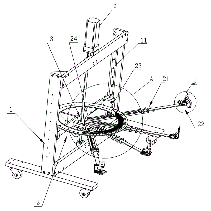
图1是本实用新型一种倒车雷达系统测试台架的立体结构示意图。Fig. 1 is a three-dimensional structural schematic diagram of a test bench for a parking radar system of the present invention.
图2是图1的A部放大结构示意图。Fig. 2 is a schematic diagram of the enlarged structure of part A of Fig. 1 .
图3是图1的B部放大结构示意图。FIG. 3 is a schematic diagram showing the enlarged structure of part B in FIG. 1 .
具体实施方式 Detailed ways
请参阅图1和图2,本实用新型一种倒车雷达系统测试台架,包括基架1、探头安装架2、丝杠螺母机构3。Please refer to FIG. 1 and FIG. 2 , a test stand for a parking radar system of the present invention includes a base frame 1 , a probe mounting frame 2 , and a lead screw nut mechanism 3 .
探头安装架2通过丝杠螺母机构3可竖直升降地连接在所述基架1上,探头安装架2用于安装探头(图中未示出)。The probe mounting frame 2 is vertically connected to the base frame 1 via a screw nut mechanism 3, and the probe mounting frame 2 is used for mounting a probe (not shown in the figure).
探头安装架2包括升降架20、水平杆21、探头安装座22;升降架20通过丝杠螺母机构3连接在基架1上,在丝杠螺母机构3的驱动下可以竖直升降,基架1上设有可引导该升降架20升降的导柱11,以保证该升降架20能平稳地升降;为了使该升降架20的升降准确并能直接得到升降值,丝杠螺母机构3由步进电机5驱动,并且在导柱11上设有可标示升降架20的高度的第一标尺(图中未示出)。The probe mounting frame 2 includes a lifting frame 20, a horizontal rod 21, and a
水平杆21包括固定杆211、以及滑动杆212和调整螺钉214;固定杆211的一端开设有第一贯通孔,第一固定螺栓24的螺杆段穿过该第一贯通孔螺接在升降架20上,将该固定杆211水平地固定在升降架20上,当需要调整该水平杆21的水平角度时,旋松该第一固定螺栓24就可转动水平杆21进行角度调整,调整完毕后拧紧该第一固定螺栓24,将该固定杆211固定;为了能定量准确地调整该水平杆21的水平角度,在升降架20上设有可标示水平杆21的水平角度位置的第一角度显示盘23,该水平杆21的固定杆211上设有指向该第一角度显示盘23上的刻度的第一指针217。固定杆211上开设有沿该固定杆211纵向延伸且横截面呈U型的滑槽210,滑动杆212可滑动地插设在该滑槽210中;该固定杆211上固定有横贯该滑槽210的固定带213,该固定带213位于远离固定杆211与升降架20连接部的部位上,调整螺钉214螺接在该固定带213上并可抵顶该滑动杆212,将滑动杆212定位在该固定杆211上;固定杆211上设有可标示该滑动杆212伸出固定杆211长度的第二标尺216;探头安装座22安装在该滑动杆212上。The horizontal rod 21 includes a fixed rod 211, a
请参阅图3,探头安装座22包括水平角度调节块231、竖直角度调节块232、探头安装板239。Please refer to FIG. 3 , the
水平角度调节块231上开设有第二贯通孔,第二固定螺栓237的螺杆段穿过该第二贯通孔螺接在滑动杆212上的远离固定杆211的部位上,将该水平角度调节块231水平安装在滑动杆212上,当需要调整该水平角度调节块231的水平角度时,旋松该第二固定螺栓237就可转动水平角度调节块231进行角度调整,调整完毕后拧紧该第二固定螺栓237,将该水平角度调节块231固定;为了能定量准确地调整该水平角度调节块231的水平角度,在滑动杆212上设有可标示水平角度调节块231的水平角度位置的第二角度显示盘233,该水平角度调节块231上设有指向该第二角度显示盘233上的刻度的第二指针235。The horizontal
竖直角度调节块232呈L型,其短臂上开设有第三贯通孔,第三固定螺栓238的螺杆段穿过该第三贯通孔螺接在所述水平角度调节块231的一竖直面上,将该竖直角度调节块232固定在水平角度调节块231上,当需要调整该竖直角度调节块232的垂直时,旋松该第三固定螺栓238就可转动竖直角度调节块232进行角度调整,调整完毕后拧紧该第三固定螺栓238,将该竖直角度调节块232固定;为了能定量准确地调整该竖直角度调节块232的垂直角度,在水平角度调节块231上设有可标示竖直角度调节块232的垂直位置的第三角度显示盘234,该竖直角度调节块232上设有指向该第三角度显示盘234上的刻度的第三指针236;探头安装板239固定在该竖直角度调节块232的长臂上,用于安装固定探头。The vertical
采用上述结构后,由于升降架20在步进电机5的驱动下能准确升降;安装在升降架20上的水平杆21的水平角度和长度可以调整,并且可根据不同的车型,设置不同数量的水平杆21;探头安装座22的探头安装板239可以通过水平角度调节块231和竖直角度调节块232分别调整水平角度和垂直角度,因此安装在探头安装板239上的探头的位置可以根据同一车型的不同高度测试的需要和对不同高度的车型的测试需要进行方便地调节。After the above-mentioned structure is adopted, since the lifting frame 20 can be lifted and lowered accurately under the drive of the stepping motor 5; Horizontal rod 21; the
Claims (13)
Priority Applications (1)
| Application Number | Priority Date | Filing Date | Title |
|---|---|---|---|
| CNU2007201721347U CN201145740Y (en) | 2007-09-26 | 2007-09-26 | A test bench for reversing radar system |
Applications Claiming Priority (1)
| Application Number | Priority Date | Filing Date | Title |
|---|---|---|---|
| CNU2007201721347U CN201145740Y (en) | 2007-09-26 | 2007-09-26 | A test bench for reversing radar system |
Publications (1)
| Publication Number | Publication Date |
|---|---|
| CN201145740Y true CN201145740Y (en) | 2008-11-05 |
Family
ID=40082623
Family Applications (1)
| Application Number | Title | Priority Date | Filing Date |
|---|---|---|---|
| CNU2007201721347U Expired - Lifetime CN201145740Y (en) | 2007-09-26 | 2007-09-26 | A test bench for reversing radar system |
Country Status (1)
| Country | Link |
|---|---|
| CN (1) | CN201145740Y (en) |
Cited By (8)
| Publication number | Priority date | Publication date | Assignee | Title |
|---|---|---|---|---|
| CN103163510A (en) * | 2013-02-27 | 2013-06-19 | 浙江吉利汽车研究院有限公司杭州分公司 | Static target vehicle of pre-collision safety system |
| CN104977575A (en) * | 2015-07-14 | 2015-10-14 | 芜湖市汽车产业技术研究院有限公司 | Radar test bench |
| CN105759251A (en) * | 2016-04-27 | 2016-07-13 | 江铃汽车股份有限公司 | Apparatus for checking backing radar |
| CN106133498A (en) * | 2014-04-09 | 2016-11-16 | 松下知识产权经营株式会社 | Vehicle evaluating apparatus |
| CN106249223A (en) * | 2016-08-31 | 2016-12-21 | 韦晨浩 | A kind of demarcation frame |
| CN106707264A (en) * | 2016-12-12 | 2017-05-24 | 山东康威通信技术股份有限公司 | Angle and distance testing device and method of ultrasonic probe |
| CN109959901A (en) * | 2017-12-26 | 2019-07-02 | 深圳市航盛电子股份有限公司 | A kind of reversing radar automated testing method, test equipment and storage medium |
| CN112415506A (en) * | 2020-11-03 | 2021-02-26 | 浙江海洋大学 | Unmanned ship is surveyed to shoal of fish |
-
2007
- 2007-09-26 CN CNU2007201721347U patent/CN201145740Y/en not_active Expired - Lifetime
Cited By (11)
| Publication number | Priority date | Publication date | Assignee | Title |
|---|---|---|---|---|
| CN103163510A (en) * | 2013-02-27 | 2013-06-19 | 浙江吉利汽车研究院有限公司杭州分公司 | Static target vehicle of pre-collision safety system |
| CN103163510B (en) * | 2013-02-27 | 2015-05-20 | 浙江吉利汽车研究院有限公司杭州分公司 | Static target vehicle of pre-collision safety system |
| CN106133498A (en) * | 2014-04-09 | 2016-11-16 | 松下知识产权经营株式会社 | Vehicle evaluating apparatus |
| CN104977575A (en) * | 2015-07-14 | 2015-10-14 | 芜湖市汽车产业技术研究院有限公司 | Radar test bench |
| CN105759251A (en) * | 2016-04-27 | 2016-07-13 | 江铃汽车股份有限公司 | Apparatus for checking backing radar |
| CN105759251B (en) * | 2016-04-27 | 2018-03-30 | 江铃汽车股份有限公司 | One kind examines astern radar device |
| CN106249223A (en) * | 2016-08-31 | 2016-12-21 | 韦晨浩 | A kind of demarcation frame |
| CN106707264A (en) * | 2016-12-12 | 2017-05-24 | 山东康威通信技术股份有限公司 | Angle and distance testing device and method of ultrasonic probe |
| CN109959901A (en) * | 2017-12-26 | 2019-07-02 | 深圳市航盛电子股份有限公司 | A kind of reversing radar automated testing method, test equipment and storage medium |
| CN112415506A (en) * | 2020-11-03 | 2021-02-26 | 浙江海洋大学 | Unmanned ship is surveyed to shoal of fish |
| CN112415506B (en) * | 2020-11-03 | 2023-09-05 | 浙江海洋大学 | A fish detection unmanned ship |
Similar Documents
| Publication | Publication Date | Title |
|---|---|---|
| CN207798422U (en) | The man-machine performance verification device of car belt | |
| CN103822796A (en) | Bump peristaltic test machine applicable to vehicle seat | |
| CN107192562A (en) | Shock absorber Abnormal Sound Trouble is quickly positioned and diagnostic test device | |
| CN119437912A (en) | Slope stability test device and test method | |
| CN104251759A (en) | Calibration device and method for six-dimensional force sensor of car end relationship test stand | |
| CN109738210A (en) | A performance testing device and testing method for dynamic vibration absorber of automobile drive shaft | |
| CN101387545B (en) | Ultrasonic liquid immersion transducer sound field precision measurement device | |
| CN113702954A (en) | Ultrasonic radar detection equipment | |
| CN206146524U (en) | Acoustic sensor support | |
| CN212082588U (en) | Quality testing device for opening and closing sound of automobile back door lock | |
| CN116481837B (en) | Auxiliary trolley for semi-trailer parking brake test and test method | |
| CN114526410A (en) | Land remote sensing monitoring device | |
| CN114397095B (en) | A threshold pedal assembly durability test equipment | |
| CN207963776U (en) | A kind of automobile washing plotting board | |
| CN208459025U (en) | Automobile front and rear bumper test device | |
| CN100399010C (en) | Automobile seat front seat longitudinal adjustment performance test machine | |
| CN107796626A (en) | A kind of mounting platform and its application method for automobile engine PIV measurements | |
| CN209197709U (en) | Steel ball roundness measuring device | |
| CN102589971A (en) | Head rest strength test bed frame for automobile seat | |
| CN208239211U (en) | Sedan car side door strength test device | |
| CN207850851U (en) | A kind of automotive seat harness buckling test device | |
| CN207689666U (en) | Reversing sensor test system | |
| CN213180686U (en) | Loudspeaker press-sound force measuring equipment | |
| CN221302704U (en) | Test bench and AR-HUD test system | |
| CN209069157U (en) | Steering wheel adjusts assembly |
Legal Events
| Date | Code | Title | Description |
|---|---|---|---|
| C14 | Grant of patent or utility model | ||
| GR01 | Patent grant | ||
| CX01 | Expiry of patent term | ||
| CX01 | Expiry of patent term |
Granted publication date: 20081105 |