CN201140000Y - Dish type vacuum filter distribution dish - Google Patents
Dish type vacuum filter distribution dish Download PDFInfo
- Publication number
- CN201140000Y CN201140000Y CN 200720016306 CN200720016306U CN201140000Y CN 201140000 Y CN201140000 Y CN 201140000Y CN 200720016306 CN200720016306 CN 200720016306 CN 200720016306 U CN200720016306 U CN 200720016306U CN 201140000 Y CN201140000 Y CN 201140000Y
- Authority
- CN
- China
- Prior art keywords
- vacuum filter
- gas distribution
- distribution plate
- ore
- vacuum
- Prior art date
- Legal status (The legal status is an assumption and is not a legal conclusion. Google has not performed a legal analysis and makes no representation as to the accuracy of the status listed.)
- Expired - Fee Related
Links
Images

Abstract
The utility model provides an air distribution disc of a disc vacuum filter, which is characterized in that a bridge plate of the existing air distribution disc is structurally improved, and the ore absorbing angle of the bridge plate of the existing air distribution disc is increased by 6 degrees to 12 degrees. The air distribution disc of a disc vacuum filter has the advantages that the ore absorbing angle is increased, and the range of a vacuum filtrating area is enlarged, thereby increasing the ore absorption capacity. The production capacity and the production quality of the existing disc vacuum filter can be increased by the improvement of the utility model.
Description
Technical field
The utility model belongs to the dewatering machine technical field, is specifically related to a kind of disk vacuum filter gas distribution plate of mine ore dressing machinery.
Background technology
In technical field dewatering operations such as iron ore concentrate, non-ferrous metal concentrate, nonmetallic ore, papermaking and chemical industry, often use disk vacuum filter.Disk vacuum filter be with vacuum as filtering power, make slurry carry out the equipment of Separation of Solid and Liquid; The dewatering operation that is suitable for fields such as iron ore concentrate, non-ferrous metal concentrate, clean fine coal, nonmetallic ore and chemical industry.
As shown in Figure 2, disk vacuum filter is a kind of solid-liquid separating equipment, filtering disk b drives by stepless speed regulation variable-speed motor and worm and wormwheel, make filter disk b in being full of the storage ore deposit groove d of ore pulp with certain rotational speed, when filtration disk b enters vacuum filtration district I, ore pulp becomes filtrate by filtering disk b in the storage ore deposit groove d under vacuum action, and filtrate is discharged to outside the machine through filtrate pipe and gas distribution plate a.Solid particle is attracted on the filter cloth of filtering table b both sides in the ore pulp becomes filter cake.When filtering disk b and produce mineral syrup liquid c and forward vacuum dehydration district II to, established filter cake leaves mineral syrup liquid c, continues sucking-off moisture under vacuum action.When forwarding mining area IV to, compressed air just blows off and filters the filter cake of disk b both sides in gas distribution plate a blows to sector disk b, and filter cake is discharged to outside the machine through the ore deposit groove e that falls.For preventing settling ore pulp, be equipped with paddle f in device bottom.From gas distribution plate a, be provided with two dead band III and V, its effect is that vacuum filtration district I and vacuum dehydration district II and the mining area IV that falls are separated, and with anti-channeling wind effect vacuum and discharging effect, will finish the work of online flushing filter cloth at dead band V simultaneously.Zhou Er renews continuously and carries out like this.
Gas distribution plate is the most important parts of this equipment in the filter, and the structure of these parts has a significant impact the efficient and the maintenance of disk vacuum filter, and the gas distribution plate effect all is the same in the filter, just the structure difference.The U.S. ends female section filter structurally relatively rationally comparatively speaking, the air-breathing time of this vacuum gas distribution plate parts is not interrupted, but this gas distribution plate vacuum filtration district be 74 ° its dead angle about 10 ° is arranged when vacuumizing, be not fully used, the ability in ore deposit is inhaled in the influence of the size of vacuum filtration district I (promptly inhaling the angle, ore deposit) as seen from Figure 2.
The utility model content
The utility model provides a kind of disk vacuum filter gas distribution plate, to solve the problems referred to above that existing disk vacuum filter gas distribution plate exists.
The purpose of this utility model is achieved in that the suction ore deposit angle with the gas distribution plate bridge plate increases α degree angle, and α=6 °~12 ° have the dead angle about 10 ° to utilize when vacuumizing, and enlarge vacuum filtration district scope, increase the ore deposit ability of inhaling.
Advantage of the present utility model and effect are, have increased suction ore deposit angle, enlarge vacuum filtration district scope, increase the ore deposit ability of inhaling, and by improvement of the present utility model the production capacity and the product quality of existing disk vacuum filter are improved.
Description of drawings
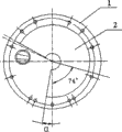
Accompanying drawing 1 is a structural representation of the present utility model;
Accompanying drawing 2 is the fundamental diagram of disk filter.
The specific embodiment
Below in conjunction with accompanying drawing the specific embodiment of the present utility model is elaborated.
As shown in Figure 1, the utility model will have now on the structure of gas distribution plate Bridge 1 plate and be improved, and the suction ore deposit angle of gas distribution plate bridge plate 2 is increased α degree angle, and α=6 °~12 ° enlarge vacuum filtration district scope, increase the ore deposit ability of inhaling; Experiment showed, that for Ys series disk vacuum filter gas distribution plate when α=9 °, its effect is best, inhales the thickness that the ore deposit time can increase filter cake by increasing, also can increase usage factor and reduce the moisture content of concentrate, enhance productivity and the quality of product.
Claims (2)
1, a kind of disk vacuum filter gas distribution plate is characterized in that bridge plate (2) architecture advances to gas distribution plate (1), and the suction ore deposit angle of its gas distribution plate bridge plate (2) increases α degree angle.
2, disk vacuum filter gas distribution plate according to claim 1 is characterized in that, it is 6 °~12 ° that described gas distribution plate bridge plate (2) is inhaled ore deposit angle increase angle [alpha].
Priority Applications (1)
| Application Number | Priority Date | Filing Date | Title |
|---|---|---|---|
| CN 200720016306 CN201140000Y (en) | 2007-11-27 | 2007-11-27 | Dish type vacuum filter distribution dish |
Applications Claiming Priority (1)
| Application Number | Priority Date | Filing Date | Title |
|---|---|---|---|
| CN 200720016306 CN201140000Y (en) | 2007-11-27 | 2007-11-27 | Dish type vacuum filter distribution dish |
Publications (1)
| Publication Number | Publication Date |
|---|---|
| CN201140000Y true CN201140000Y (en) | 2008-10-29 |
Family
ID=40067717
Family Applications (1)
| Application Number | Title | Priority Date | Filing Date |
|---|---|---|---|
| CN 200720016306 Expired - Fee Related CN201140000Y (en) | 2007-11-27 | 2007-11-27 | Dish type vacuum filter distribution dish |
Country Status (1)
| Country | Link |
|---|---|
| CN (1) | CN201140000Y (en) |
Cited By (3)
| Publication number | Priority date | Publication date | Assignee | Title |
|---|---|---|---|---|
| CN103520989A (en) * | 2013-10-31 | 2014-01-22 | 北方重工集团有限公司 | Air distributing device for vacuum filter |
| CN105833598A (en) * | 2016-06-15 | 2016-08-10 | 安徽华电宿州发电有限公司 | Distributing head of disk dewatering machine |
| CN112403088A (en) * | 2020-12-17 | 2021-02-26 | 辽宁五寰特种材料与智能装备产业技术研究院有限公司 | Novel double-vacuum disc type filter |
-
2007
- 2007-11-27 CN CN 200720016306 patent/CN201140000Y/en not_active Expired - Fee Related
Cited By (4)
| Publication number | Priority date | Publication date | Assignee | Title |
|---|---|---|---|---|
| CN103520989A (en) * | 2013-10-31 | 2014-01-22 | 北方重工集团有限公司 | Air distributing device for vacuum filter |
| CN105833598A (en) * | 2016-06-15 | 2016-08-10 | 安徽华电宿州发电有限公司 | Distributing head of disk dewatering machine |
| CN112403088A (en) * | 2020-12-17 | 2021-02-26 | 辽宁五寰特种材料与智能装备产业技术研究院有限公司 | Novel double-vacuum disc type filter |
| CN112403088B (en) * | 2020-12-17 | 2022-04-29 | 辽宁五寰特种材料与智能装备产业技术研究院有限公司 | Double-vacuum disc type filter |
Similar Documents
| Publication | Publication Date | Title |
|---|---|---|
| CN105524669B (en) | Coal gasification fine slag sorts and the method for reuse | |
| CN106733141B (en) | A kind of compound poor iron ore pre-selection production system | |
| CN103045777B (en) | Dry processing technique for iron-containing steel slag | |
| CN102092569A (en) | Spiral conveyor | |
| CN201140000Y (en) | Dish type vacuum filter distribution dish | |
| CN108392878A (en) | A kind of vertical coal slurry dewaterer | |
| CN207271464U (en) | A kind of tailing dry row's equipment that can be improved efficiency and reduce cost | |
| CN101966485B (en) | Before-filtering magnetic separator concentrating process | |
| CN2782219Y (en) | Hydraulic power separator | |
| CN106237708A (en) | A kind of Coal Preparation Plant coal slime dewatering system and method | |
| CN208894380U (en) | A kind of medicinal herb grinder group | |
| CN208166951U (en) | A kind of coal chemical industry gasified coal water slurry concentrate process units | |
| CN202638581U (en) | Horizontal eddy dry-type magnetic separator | |
| CN105396702A (en) | Fine coal centrifugal separation equipment capable of discharging materials continuously | |
| CN207126648U (en) | A kind of charcoal water wash system | |
| CN202683333U (en) | Shearing-type rinsing drum-type weak magnetic separator | |
| CN205628156U (en) | Integration industry solid waste continuous separation equipment | |
| CN201140001Y (en) | Dish type vacuum filter distribution dish | |
| CN104128033B (en) | A kind of high voltage double-layer filter for steel rolling Treatment of Sludge | |
| CN201064775Y (en) | Separator | |
| CN201923611U (en) | Spiral conveyer | |
| CN208468117U (en) | Shot-blasting machine with online pellet filter device | |
| CN206168075U (en) | Thermal coal coal separating plant coal slime dewatering system | |
| CN206028105U (en) | A portable screening machine for ceramsite filter production | |
| CN206965924U (en) | A kind of activated coke raw material iron removaling screening plant |
Legal Events
| Date | Code | Title | Description |
|---|---|---|---|
| C14 | Grant of patent or utility model | ||
| GR01 | Patent grant | ||
| CF01 | Termination of patent right due to non-payment of annual fee |
Granted publication date: 20081029 Termination date: 20151127 |