CN201125835Y - Faucet Generator - Google Patents

Faucet Generator Download PDF

Info

Publication number
CN201125835Y
CN201125835Y CNU2007201831370U CN200720183137U CN201125835Y CN 201125835 Y CN201125835 Y CN 201125835Y CN U2007201831370 U CNU2007201831370 U CN U2007201831370U CN 200720183137 U CN200720183137 U CN 200720183137U CN 201125835 Y CN201125835 Y CN 201125835Y
Authority
CN
China
Prior art keywords
impeller
rectifier
water tap
generating device
electricity generating
Prior art date
Legal status (The legal status is an assumption and is not a legal conclusion. Google has not performed a legal analysis and makes no representation as to the accuracy of the status listed.)
Expired - Fee Related
Application number
CNU2007201831370U
Other languages
Chinese (zh)
Inventor
占财兴
Current Assignee (The listed assignees may be inaccurate. Google has not performed a legal analysis and makes no representation or warranty as to the accuracy of the list.)
Construction Engineering Science & Technology Institute Co Ltd Of Xinjiang Production And Construction Corps
Original Assignee
Construction Engineering Science & Technology Institute Co Ltd Of Xinjiang Production And Construction Corps
Priority date (The priority date is an assumption and is not a legal conclusion. Google has not performed a legal analysis and makes no representation as to the accuracy of the date listed.)
Filing date
Publication date
Application filed by Construction Engineering Science & Technology Institute Co Ltd Of Xinjiang Production And Construction Corps filed Critical Construction Engineering Science & Technology Institute Co Ltd Of Xinjiang Production And Construction Corps
Priority to CNU2007201831370U priority Critical patent/CN201125835Y/en
Application granted granted Critical
Publication of CN201125835Y publication Critical patent/CN201125835Y/en
Anticipated expiration legal-status Critical
Expired - Fee Related legal-status Critical Current

Links

Images

Classifications

    • Y—GENERAL TAGGING OF NEW TECHNOLOGICAL DEVELOPMENTS; GENERAL TAGGING OF CROSS-SECTIONAL TECHNOLOGIES SPANNING OVER SEVERAL SECTIONS OF THE IPC; TECHNICAL SUBJECTS COVERED BY FORMER USPC CROSS-REFERENCE ART COLLECTIONS [XRACs] AND DIGESTS
    • Y02—TECHNOLOGIES OR APPLICATIONS FOR MITIGATION OR ADAPTATION AGAINST CLIMATE CHANGE
    • Y02E—REDUCTION OF GREENHOUSE GAS [GHG] EMISSIONS, RELATED TO ENERGY GENERATION, TRANSMISSION OR DISTRIBUTION
    • Y02E10/00—Energy generation through renewable energy sources
    • Y02E10/20—Hydro energy

Landscapes

  • Connection Of Motors, Electrical Generators, Mechanical Devices, And The Like (AREA)
  • Other Liquid Machine Or Engine Such As Wave Power Use (AREA)

Abstract

本实用新型公开了一种水龙头发电装置,包括管体,在管体内设置着具有水流通道的支撑架,支撑架与管体轴线相垂直,在支撑架上安装着叶轮,叶轮叶片的外周缘上分别设置着磁铁块,在叶轮四周的管体内壁上嵌装着封闭线圈,线圈通过导线与安装在管体内壁中的整流器相连,整流器外接用电器。使用时,将其安装在水龙头出口处,水流就会冲刷叶轮推其旋转进行发电并通过整流器供外接用电器使用。

Figure 200720183137

The utility model discloses a faucet power generation device, which comprises a pipe body. A support frame with a water flow channel is arranged in the pipe body. The support frame is perpendicular to the axis of the pipe body. An impeller is installed on the support frame. Magnet blocks are arranged respectively, and a closed coil is embedded on the inner wall of the tube around the impeller, and the coil is connected with a rectifier installed in the inner wall of the tube through a wire, and the rectifier is externally connected to an electrical appliance. When in use, it is installed at the outlet of the faucet, and the water flow will flush the impeller and push it to rotate to generate electricity and supply it to external electrical appliances through the rectifier.

Figure 200720183137

Description

The water tap electricity generating device
Technical field
The utility model relates to a kind of simple and easy electricity generating device, particularly a kind of water tap electricity generating device that utilizes the current generating on the water tap that is installed in.
Background technique
At present, people have developed various electricity generating devices, as flashlight with electric generation by itself.By rocking flashlight back and forth, the magnet piece in the flashlight moves back and forth and makes the encapsulated coil cutting magnetic line in the flashlight will produce electric current, makes the bulb of flashlight light.Be similar to so simple and easy electricity generating device and also have a lot, they have greatly enriched people's life.
The model utility content
The purpose of this utility model is to provide a kind of water tap electricity generating device, it is installed in just can utilizes current to generate electricity on the water tap, and it is simple in structure, is easy to make low production cost.
The purpose of this utility model is achieved in that a kind of water tap electricity generating device, comprise body, supporting frame with flow channel is being set in body, supporting frame and body axis are perpendicular, impeller is installed on supporting frame, magnet piece is being set respectively on the outer periphery of impeller blade, setting-in encapsulated coil on the inboard wall of tube body around the impeller, coil links to each other the external electric consumer of rectifier by lead with rectifier in being installed in inboard wall of tube body.
When the utility model uses, body is installed on the water tap, open switch, current will promote the impeller high speed rotating, the magnetic line of force that produces of encapsulated coil septum magnet piece like this, just can utilize current to generate electricity, the Ac of generation just can use for external electric consumer (such as little electric consumers such as electric shaver, flashlight, charger for mobile phone) after by rectifier rectification.So neither influencing water tap and use, can utilize the current generating again, is a kind of simple and easy electricity generating device of small and exquisite practicality.The utility model is simple in structure, is easy to make, and low production cost is easy to promote.
Description of drawings
The utility model is described in further detail below in conjunction with accompanying drawing.
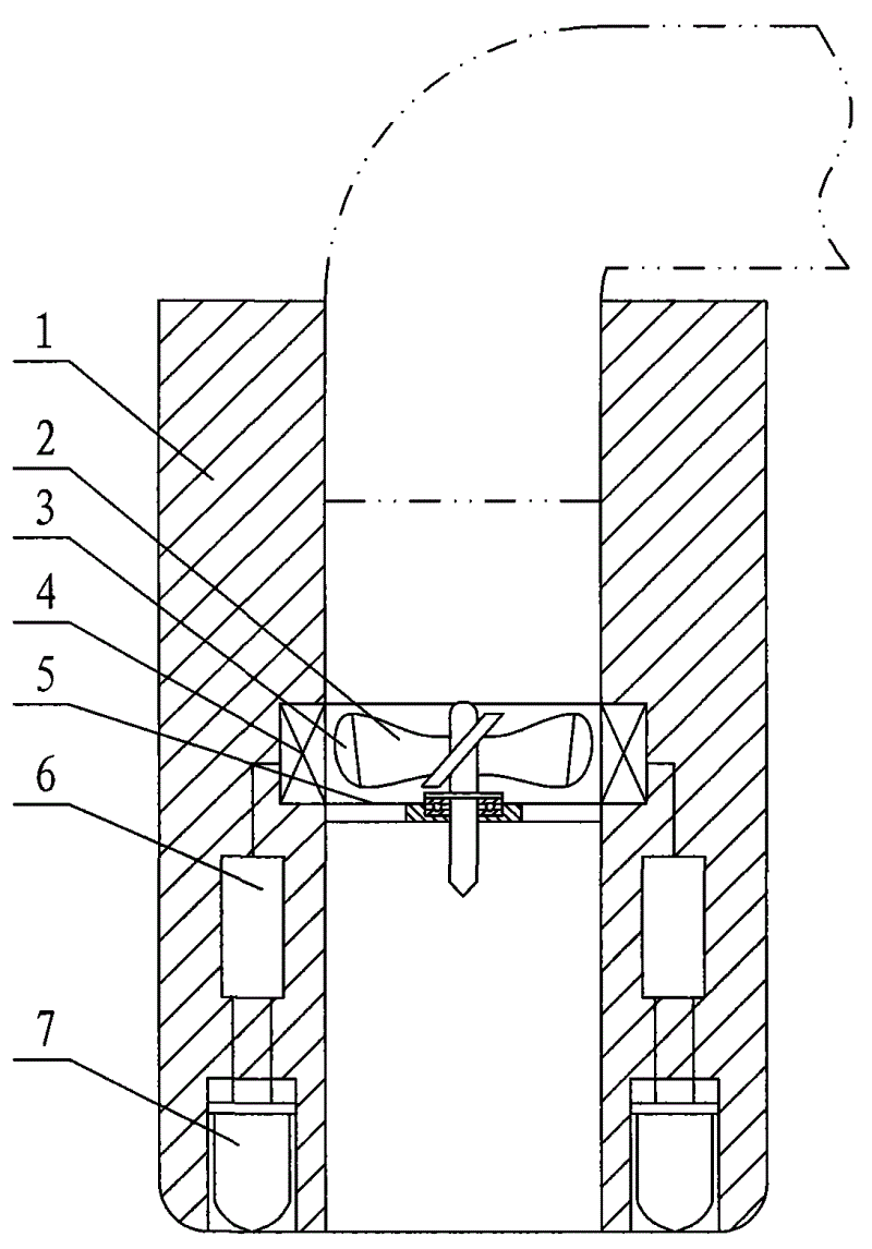
Fig. 1 looks cross-sectional view for master of the present utility model;
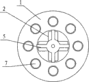
Fig. 2 is a worm's eye view of the present utility model.
Embodiment
A kind of water tap electricity generating device as shown in Figure 1 and Figure 2, comprises body 1, and the supporting frame 5 with flow channel is being set in body 1, and supporting frame 5 is cross.Supporting frame 5 is perpendicular with the body axis, impeller 2 by Bearing Installation on supporting frame 5, and under the impact of current, impeller 2 can high speed rotating.On the outer periphery of impeller 2 blades magnet piece 3 is being set respectively, setting-in encapsulated coil 4 on the inboard wall of tube body around the impeller 2.During impeller 2 rotation, the magnetic line of force that encapsulated coil 4 will septum magnet piece 3 produces Ac.Coil 4 links to each other with rectifier 6 in being installed in inboard wall of tube body by lead, and rectifier 6 external electric consumers (such as little electric consumers such as electric shaver, flashlight, charger for mobile phone) use.Charging circuit and storage battery or large value capacitor can also be set in inboard wall of tube body, can be stored into the electric current that produces in storage battery or the capacitor stand-by like this.
At body 1 end inner sealing LED lamp 7 is being set, LED lamp 7 and rectifier 6 link to each other by lead.Said LED lamp 7 is uniform ringwise to be arranged in body 1 end.The utility model can be become a power generation flashlight like this, use temporarily for people.
In actual use,, can also blow, blow impeller 2 rotary electrifications by air-flow facing to body 1 if use in the place that does not have water tap.

Claims (3)

1, a kind of water tap electricity generating device, comprise body (1), it is characterized in that: the supporting frame (5) with flow channel is being set in body (1), supporting frame (5) is perpendicular with the body axis, impeller (2) is installed on supporting frame (5), on the outer periphery of impeller (2) blade magnet piece (3) is being set respectively, setting-in encapsulated coil (4) on impeller (2) inboard wall of tube body all around, coil (4) links to each other the external electric consumer of rectifier (6) by lead with rectifier (6) in being installed in inboard wall of tube body.
2, water tap electricity generating device according to claim 1 is characterized in that: inner sealing is being provided with LED lamp (7) in body (1) end, and LED lamp (7) links to each other by lead with rectifier (6).
3, water tap electricity generating device according to claim 2 is characterized in that: said LED lamp (7) is uniform ringwise to be arranged in body (1) end.
CNU2007201831370U 2007-11-09 2007-11-09 Faucet Generator Expired - Fee Related CN201125835Y (en)

Priority Applications (1)

Application Number Priority Date Filing Date Title
CNU2007201831370U CN201125835Y (en) 2007-11-09 2007-11-09 Faucet Generator

Applications Claiming Priority (1)

Application Number Priority Date Filing Date Title
CNU2007201831370U CN201125835Y (en) 2007-11-09 2007-11-09 Faucet Generator

Publications (1)

Publication Number Publication Date
CN201125835Y true CN201125835Y (en) 2008-10-01

Family

ID=39999304

Family Applications (1)

Application Number Title Priority Date Filing Date
CNU2007201831370U Expired - Fee Related CN201125835Y (en) 2007-11-09 2007-11-09 Faucet Generator

Country Status (1)

Country Link
CN (1) CN201125835Y (en)

Cited By (4)

* Cited by examiner, † Cited by third party
Publication number Priority date Publication date Assignee Title
CN102787960A (en) * 2011-05-17 2012-11-21 上海天净管业有限公司 Hydroelectric generator system provided with external stator and arranged on water pipeline
CN103225876A (en) * 2013-05-13 2013-07-31 山东大学 Water self-heating device
CN103457411A (en) * 2013-05-09 2013-12-18 陈飞 Illuminating device for power generation through sprayed streams
CN105626357A (en) * 2016-03-15 2016-06-01 陕西科技大学 Energy-saving power generation device capable of being additionally arranged on water pipe

Cited By (5)

* Cited by examiner, † Cited by third party
Publication number Priority date Publication date Assignee Title
CN102787960A (en) * 2011-05-17 2012-11-21 上海天净管业有限公司 Hydroelectric generator system provided with external stator and arranged on water pipeline
CN103457411A (en) * 2013-05-09 2013-12-18 陈飞 Illuminating device for power generation through sprayed streams
CN103225876A (en) * 2013-05-13 2013-07-31 山东大学 Water self-heating device
CN103225876B (en) * 2013-05-13 2015-09-09 山东大学 Self-heating plumbing fixture
CN105626357A (en) * 2016-03-15 2016-06-01 陕西科技大学 Energy-saving power generation device capable of being additionally arranged on water pipe

Similar Documents

Publication Publication Date Title
CN103835867B (en) A kind of countryside portable waterpower wind-force compensating generator
CN103967688A (en) Water flow power generation device
CN202533127U (en) Self-generating remote-transmission water meter device without power source
CN102147277A (en) Electronic water meter with permanent magnetic generator
CN201926477U (en) Electronic water meter with permanent magnet generator
CN204476646U (en) A kind of small-sized household hydroelectric generator
CN204961166U (en) wind power plant
CN202092703U (en) Electronic water flow meter provided with hydroelectric generator
CN103375752B (en) Lamp fitting
CN207038096U (en) A water pipe self-generating sign device driven by a vertical axis water turbine
CN201159130Y (en) A power generating device installed in a pipeline
CN205423046U (en) Can install energy -saving power generation equipment on water pipe additional
CN201810464U (en) Hydroelectric power supply device of gas water heater
CN104179627B (en) A kind of Miniature flow generator
CN210343573U (en) A hydroelectric device
CN201666211U (en) Water pipe power generation device and radio using water pipe power generation device to generate electricity
CN206477946U (en) Micro-hydro generator
CN105626357B (en) A kind of energy-saving generating plant being installed on water pipe
CN103216387B (en) Two to rotary electrification equipment
CN201680026U (en) Power generation valve body
CN101825051A (en) Running water pipe electricity generator and radio using running water pipe electricity generator for generating electricity
CN201034062Y (en) Energy-saving charger
CN201153218Y (en) A mobile phone self-generating device
CN201696201U (en) A miniature through-flow hydroelectric power generation device for building water supply system
CN205532996U (en) Rivers energy conversion device

Legal Events

Date Code Title Description
C14 Grant of patent or utility model
GR01 Patent grant
C17 Cessation of patent right
CF01 Termination of patent right due to non-payment of annual fee

Granted publication date: 20081001

Termination date: 20101109