CN201120491Y - Single end blade chip flute R butt mill - Google Patents
Single end blade chip flute R butt mill Download PDFInfo
- Publication number
- CN201120491Y CN201120491Y CNU2007203057416U CN200720305741U CN201120491Y CN 201120491 Y CN201120491 Y CN 201120491Y CN U2007203057416 U CNU2007203057416 U CN U2007203057416U CN 200720305741 U CN200720305741 U CN 200720305741U CN 201120491 Y CN201120491 Y CN 201120491Y
- Authority
- CN
- China
- Prior art keywords
- milling cutter
- corner part
- round corner
- rake face
- cutter
- Prior art date
- Legal status (The legal status is an assumption and is not a legal conclusion. Google has not performed a legal analysis and makes no representation as to the accuracy of the status listed.)
- Expired - Fee Related
Links
Images

Abstract
The utility model relates to a single-end edge chip flute R end milling cutter. A circumferential cutting edge rake face and an R round corner part rake face adopt the smooth connection on the space curved surface, and the R round corner part has a changing rake angle structure. The circumferential cutting edge is in smooth connection with the R round corner part and has no inflection point. The R end milling cutter can improve the chip discharge performance and contour precision of the R milling cutter, and can strictly control the rake angle of the R round corner part and ensure the sharpness of the cutting edge. The R end milling cutter can improve the stability of cutting tools used in batches and the machining efficiency of the cutting tools and extend the service life by 50 percent, thereby reducing the use cost of the cutting tool.
Description
Affiliated field: the utility model relates to the R slotting cutter with single-ended sword chip pocket.
Background technology:
The R slotting cutter is mainly used in the clear angle processing of workpiece bottom land R as an important component part in the machining usefulness cutter, and the copying of forming surface.Along with popularizing of Digit Control Machine Tool, Computerized Numerical Control processing technology increasingly mature, each cutter uses crudy, manufacturing cost, the process reliability of merchant to product, and working (machining) efficiency has all proposed high requirement.The structure that traditional R milling cutter adopts end sword rake face to impose uniformity without examining individual cases owing to the R rake face is not carried out respective handling, causes its contour curve irregular, causes R fillet precision extremely unstable, and product processed does not more have precision and can say; At milling cutter end sword rake face and all sword rake faces of milling cutter joint step is arranged, and its space is narrow and small, causes smear metal to be flowed out and has some setbacks, the smear metal retardance, it is scarce to cause that easily cutter tooth collapses in roughing feed processing, can not carry out high efficiency processing; Cutting edge is not sharp, and cutting edge is discontinuous, and chip deformation is big during cutting, and resistance to cutting is big, causes processing vibration aggravation, causes cutter to collapse damage; Cutter depends primarily on other structures in the shape at R rake face place, so its structure changes with its dependency structure, as helical angle, all angle of cutting edge, end angle of cutting edge etc., this causes its control difficulty big, is difficult to guarantee consistency of product.
Summary of the invention:
The purpose of this utility model is that design a kind ofly can improve the chip removal performance of R milling cutter, the milling cutter of contour accuracy, improves the stability that cutter uses in batches, improves the working (machining) efficiency of cutter, prolongs cutter life, thereby reduces the use cost of cutter.The purpose of this utility model realizes by the following method: the anterior angle at control R fillet position guarantees that cutting edge is sharp.Week, the sword rake face adopted with R position rake face that space curved surface is smooth to be connected, and R fillet position is seamlessly transitted by Zhou Ren and fillet position for becoming preceding corner structure.Characteristics of the present utility model are: 1, R fillet precision is high and can stablize control.Because this milling cutter construction is to carry out the transition to fillet position rake face gradually from all sword rake faces, accurately controls its grinding track by special processing equipment, and on this track, carry out relief angle processing, so the precision of R fillet is high and stable.2, chip removal is smooth and easy.On former end sword rake face basis, widened chip space 30%, and owing to be connected with the space smooth surface between fillet position rake face and all sword rake faces, the smear metal smoothness of on rake face, sliding.The good fluidity of smear metal can adopt roughing feed processing, thereby improve machining efficient.3, cutting ability is good.Cutting edge is smooth transition from the end sword to Zhou Ren, cuts workpiece gradually, has avoided the unexpected variation of cutting force, thereby suppresses vibration cutting.This R slotting cutter anterior angle is sharp, and chip deformation is little, and cutting resistance is little, and tool wear is slow and wearing and tearing are even, reaches 50% thereby can improve cutter life.Can guarantee the processing stability produced in batches.
Description of drawings:
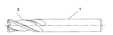
Fig. 1 is the single-ended sword chip pocket of a utility model R slotting cutter overall structure schematic diagram.
Fig. 2 is that the single-ended sword chip pocket of the utility model R slotting cutter nose part is divided local enlarged drawing.
The specific embodiment:
As shown in Figure 1, the utility model is a kind of single-ended sword chip pocket R slotting cutter, and this milling cutter is a bar type structure.Among Fig. 1,1 is shank, and 2 is blade.
Fig. 2 is this R milling cutter point of a knife fillet position enlarged drawing, 3 is end blade branch shown in (a), and 4 is the fillet part, and 5 is all blade branches.The A point is the fillet rake face and the contact mutually of Zhou Ren.Angle Y defines the position that A is ordered, and the scope of Y is-20 °~+ 45 °.(b) Q of angle shown in is the angle of end sword and Zhou Ren, and its span is 89 °~75 °.
Version key of the present utility model is that the anterior angle at R fillet position changes, and guarantees fillet position rake face and all sword rake face smooth transition, thereby it is smooth that smear metal is discharged.Guarantee the contour accuracy at R fillet position by reliable process equipment.The anterior angle of this milling cutter is sharp, and cutting edge from the fillet position to all sword transition slynesses, excellent cutting performance suppresses to occur vibration in the processing, thereby guarantees crudy, prolongs cutter life.
Claims (1)
1. single-ended sword chip pocket R slotting cutter, it is characterized in that: slotting cutter is a bar type structure, and all sword rake faces adopt with R fillet position rake face that space curved surface is smooth to be connected, and R fillet position is corner structure before becoming.
Priority Applications (1)
| Application Number | Priority Date | Filing Date | Title |
|---|---|---|---|
| CNU2007203057416U CN201120491Y (en) | 2007-11-16 | 2007-11-16 | Single end blade chip flute R butt mill |
Applications Claiming Priority (1)
| Application Number | Priority Date | Filing Date | Title |
|---|---|---|---|
| CNU2007203057416U CN201120491Y (en) | 2007-11-16 | 2007-11-16 | Single end blade chip flute R butt mill |
Publications (1)
| Publication Number | Publication Date |
|---|---|
| CN201120491Y true CN201120491Y (en) | 2008-09-24 |
Family
ID=40007711
Family Applications (1)
| Application Number | Title | Priority Date | Filing Date |
|---|---|---|---|
| CNU2007203057416U Expired - Fee Related CN201120491Y (en) | 2007-11-16 | 2007-11-16 | Single end blade chip flute R butt mill |
Country Status (1)
| Country | Link |
|---|---|
| CN (1) | CN201120491Y (en) |
Cited By (3)
| Publication number | Priority date | Publication date | Assignee | Title |
|---|---|---|---|---|
| CN102264496A (en) * | 2009-01-21 | 2011-11-30 | 三菱综合材料株式会社 | Radius end mill |
| CN106925826A (en) * | 2017-04-05 | 2017-07-07 | 苏州市联佳精密机械有限公司 | The process tool of aviation interior trim aluminium alloy component |
| CN109794634A (en) * | 2019-03-05 | 2019-05-24 | 苏州阿诺精密切削技术有限公司 | A kind of roughing bulk ceramics milling cutter |
-
2007
- 2007-11-16 CN CNU2007203057416U patent/CN201120491Y/en not_active Expired - Fee Related
Cited By (4)
| Publication number | Priority date | Publication date | Assignee | Title |
|---|---|---|---|---|
| CN102264496A (en) * | 2009-01-21 | 2011-11-30 | 三菱综合材料株式会社 | Radius end mill |
| CN102264496B (en) * | 2009-01-21 | 2014-05-28 | 三菱综合材料株式会社 | Radius end mill |
| CN106925826A (en) * | 2017-04-05 | 2017-07-07 | 苏州市联佳精密机械有限公司 | The process tool of aviation interior trim aluminium alloy component |
| CN109794634A (en) * | 2019-03-05 | 2019-05-24 | 苏州阿诺精密切削技术有限公司 | A kind of roughing bulk ceramics milling cutter |
Similar Documents
| Publication | Publication Date | Title |
|---|---|---|
| CN202606958U (en) | Two-blade milling cutter for high-speed cutting of aluminum | |
| CN101804478A (en) | Compound milling cutter for machining fir tree type blade root wheel groove | |
| CN201728411U (en) | Efficient cutting milling cutter with spiral taper | |
| CN201120491Y (en) | Single end blade chip flute R butt mill | |
| CN102489765A (en) | Non-slot-shared step cutter | |
| CN102266974A (en) | Coarse and fine integrated milling cutter | |
| CN204504407U (en) | Low module machine clip variable-position gear milling cutter in plate-like | |
| CN205464384U (en) | Boring machine adds cutter | |
| CN103302340B (en) | The progressive interpolation of a kind of digital control processing | |
| CN202344008U (en) | Stepped milling cutter without common groove | |
| CN209174981U (en) | A kind of assembly type high-precision end milling cutter | |
| CN211708208U (en) | Titanium alloy double-chip-groove round nose milling cutter | |
| CN201030447Y (en) | Highly effective auger-drill head | |
| CN207952739U (en) | A kind of cutting reamer cutter being processed and formed at one time for more sizes | |
| CN104174902A (en) | High-precision inner-cooling stepped drill | |
| CN112338249A (en) | Single-edge ball-end milling cutter for deep hole machining | |
| CN203281964U (en) | Efficient processing end-milling cutter | |
| CN208083535U (en) | A kind of milling cutter | |
| CN220445147U (en) | Milling cutter processing protection machanism | |
| CN211052554U (en) | Novel rhombus numerical control blade for slotting | |
| CN214079465U (en) | High-precision T-shaped hard alloy cutter | |
| CN109396517A (en) | A kind of assembly type high-precision end milling cutter | |
| CN216938597U (en) | Hard alloy milling cutter with burnishing edges | |
| CN216858357U (en) | Multi-tooth composite T-shaped milling cutter for hard alloy | |
| CN219093666U (en) | Precision grinding slotting blade |
Legal Events
| Date | Code | Title | Description |
|---|---|---|---|
| C14 | Grant of patent or utility model | ||
| GR01 | Patent grant | ||
| C17 | Cessation of patent right | ||
| CF01 | Termination of patent right due to non-payment of annual fee |
Granted publication date: 20080924 Termination date: 20091216 |