CN201097405Y - electrical connector - Google Patents
electrical connector Download PDFInfo
- Publication number
- CN201097405Y CN201097405Y CNU2007201256311U2007201256311U CN200720125631U CN201097405Y CN 201097405 Y CN201097405 Y CN 201097405Y CN U2007201256311U2007201256311 U CNU2007201256311U2007201256311 U CN U2007201256311U2007201256311U CN 200720125631 U CN200720125631 U CN 200720125631U CN 201097405 Y CN201097405 Y CN 201097405Y
- Authority
- CN
- China
- Prior art keywords
- elastic arm
- terminal
- contact
- electric connector
- electrical connector
- Prior art date
- Legal status (The legal status is an assumption and is not a legal conclusion. Google has not performed a legal analysis and makes no representation as to the accuracy of the status listed.)
- Expired - Fee Related
Links
Images


Classifications
-
- H—ELECTRICITY
- H01—ELECTRIC ELEMENTS
- H01R—ELECTRICALLY-CONDUCTIVE CONNECTIONS; STRUCTURAL ASSOCIATIONS OF A PLURALITY OF MUTUALLY-INSULATED ELECTRICAL CONNECTING ELEMENTS; COUPLING DEVICES; CURRENT COLLECTORS
- H01R12/00—Structural associations of a plurality of mutually-insulated electrical connecting elements, specially adapted for printed circuits, e.g. printed circuit boards [PCB], flat or ribbon cables, or like generally planar structures, e.g. terminal strips, terminal blocks; Coupling devices specially adapted for printed circuits, flat or ribbon cables, or like generally planar structures; Terminals specially adapted for contact with, or insertion into, printed circuits, flat or ribbon cables, or like generally planar structures
- H01R12/70—Coupling devices
- H01R12/71—Coupling devices for rigid printing circuits or like structures
- H01R12/712—Coupling devices for rigid printing circuits or like structures co-operating with the surface of the printed circuit or with a coupling device exclusively provided on the surface of the printed circuit
- H01R12/714—Coupling devices for rigid printing circuits or like structures co-operating with the surface of the printed circuit or with a coupling device exclusively provided on the surface of the printed circuit with contacts abutting directly the printed circuit; Button contacts therefore provided on the printed circuit
-
- H—ELECTRICITY
- H01—ELECTRIC ELEMENTS
- H01R—ELECTRICALLY-CONDUCTIVE CONNECTIONS; STRUCTURAL ASSOCIATIONS OF A PLURALITY OF MUTUALLY-INSULATED ELECTRICAL CONNECTING ELEMENTS; COUPLING DEVICES; CURRENT COLLECTORS
- H01R13/00—Details of coupling devices of the kinds covered by groups H01R12/70 or H01R24/00 - H01R33/00
- H01R13/02—Contact members
- H01R13/22—Contacts for co-operating by abutting
- H01R13/24—Contacts for co-operating by abutting resilient; resiliently-mounted
- H01R13/2435—Contacts for co-operating by abutting resilient; resiliently-mounted with opposite contact points, e.g. C beam
-
- H—ELECTRICITY
- H01—ELECTRIC ELEMENTS
- H01R—ELECTRICALLY-CONDUCTIVE CONNECTIONS; STRUCTURAL ASSOCIATIONS OF A PLURALITY OF MUTUALLY-INSULATED ELECTRICAL CONNECTING ELEMENTS; COUPLING DEVICES; CURRENT COLLECTORS
- H01R13/00—Details of coupling devices of the kinds covered by groups H01R12/70 or H01R24/00 - H01R33/00
- H01R13/02—Contact members
- H01R13/22—Contacts for co-operating by abutting
- H01R13/24—Contacts for co-operating by abutting resilient; resiliently-mounted
- H01R13/2457—Contacts for co-operating by abutting resilient; resiliently-mounted consisting of at least two resilient arms contacting the same counterpart
-
- H—ELECTRICITY
- H01—ELECTRIC ELEMENTS
- H01R—ELECTRICALLY-CONDUCTIVE CONNECTIONS; STRUCTURAL ASSOCIATIONS OF A PLURALITY OF MUTUALLY-INSULATED ELECTRICAL CONNECTING ELEMENTS; COUPLING DEVICES; CURRENT COLLECTORS
- H01R13/00—Details of coupling devices of the kinds covered by groups H01R12/70 or H01R24/00 - H01R33/00
- H01R13/02—Contact members
- H01R13/22—Contacts for co-operating by abutting
- H01R13/24—Contacts for co-operating by abutting resilient; resiliently-mounted
- H01R13/2464—Contacts for co-operating by abutting resilient; resiliently-mounted characterized by the contact point
- H01R13/2492—Contacts for co-operating by abutting resilient; resiliently-mounted characterized by the contact point multiple contact points
Landscapes
- Coupling Device And Connection With Printed Circuit (AREA)
Abstract
本实用新型公开了一种电连接器,用以电性连接晶片模组和印刷电路板。该电连接器包括设有若干端子收容槽的绝缘本体以及收容于相应端子收容槽内的若干导电端子。导电端子包括固持于端子收容槽内的基部以及分别自基部上下倾斜延伸的一对相对设置的弹性臂,该弹性臂可分别与两个电子元件电性接触。至少一个弹性臂中部设有开口,且自开口的一端朝向另一弹性臂方向延伸有肋骨部,当两个分离的电子元件分别压缩导电端子时,该弹性臂上的肋骨部可以与另一个弹性臂接触以减小电性导通路径。
The utility model discloses an electric connector, which is used for electrically connecting a chip module and a printed circuit board. The electrical connector includes an insulating body provided with a plurality of terminal accommodating grooves and a plurality of conductive terminals accommodated in the corresponding terminal accommodating grooves. The conductive terminal includes a base fixed in the terminal receiving groove, and a pair of opposite elastic arms extending obliquely up and down from the base respectively, and the elastic arms can electrically contact with two electronic components respectively. There is an opening in the middle of at least one elastic arm, and a rib portion extends from one end of the opening toward the other elastic arm. When two separated electronic components respectively compress the conductive terminals, the rib portion on the elastic arm can be connected with the other elastic arm. arm contact to reduce the electrical conduction path.
Description
【技术领域】【Technical field】
本实用新型关于一种电连接器,特别是一种可电性连接晶片模组和印刷电路板的电连接器。The utility model relates to an electrical connector, in particular to an electrical connector capable of electrically connecting a chip module and a printed circuit board.
【背景技术】【Background technique】
电连接器被广泛地应用于各种电子设备中,用以电性连接两个分离的电子元件,如,晶片模组和印刷电路板。其结构一般包括:设有端子收容槽的绝缘本体以及收容于上述端子收容槽中的若干导电端子。其中导电端子包括固持于端子收容槽中的基部以及自基部上下分别向上倾斜延伸的一对弹性臂,当电子元件压缩导电端子时,其弹性臂开始自初始状态开始倾斜,以在两个分离的电子元件之间提供信号传输路径。Electrical connectors are widely used in various electronic devices to electrically connect two separated electronic components, such as chip modules and printed circuit boards. Its structure generally includes: an insulating body provided with a terminal receiving groove, and a plurality of conductive terminals accommodated in the terminal receiving groove. Wherein the conductive terminal includes a base held in the terminal receiving groove and a pair of elastic arms extending obliquely upward from the base. Signal transmission paths are provided between electronic components.
然而,该种电连接器至少存在以下缺点:该电连接器的电性导通路径是这样实现的:晶片模组通过与导电端子弹性臂自由末端的接触点接触,从而将电性传到导电端子上,导电端子再将电性经由与晶片模组接触的弹性臂、基部、与印刷电路板接触的另一个弹性臂而将电性传至印刷电路板,故,该种电连接器的电性传输路径较远。However, this kind of electrical connector has at least the following disadvantages: the electrical conduction path of the electrical connector is realized in this way: the chip module contacts the contact point at the free end of the elastic arm of the conductive terminal, thereby transferring electricity to the conductive On the terminal, the conductive terminal transmits electricity to the printed circuit board through the elastic arm in contact with the chip module, the base, and another elastic arm in contact with the printed circuit board. Sexual transmission path is long.
鉴于上述缺失,确有必要提供一种改进的电连接器以克服上述缺点和不足。In view of the above deficiencies, it is indeed necessary to provide an improved electrical connector to overcome the above disadvantages and deficiencies.
【实用新型内容】【Content of utility model】
本实用新型的目的为提供一种电连接器,其可以缩短电性导通路径且具有良好的电性导通。The purpose of the utility model is to provide an electrical connector, which can shorten the electrical conduction path and has good electrical conduction.
为解决上述问题,本实用新型提供了一种电连接器,包括设有端子收容槽的绝缘本体以及收容于上述端子收容槽内的若干导电端子,每个导电端子包括固持于端子收容槽内的竖直基部以及分别自基部上下向上倾斜延伸且突出绝缘本体的一对弹性臂,其中每个弹性臂自由末端至少设有两个接触点以提供良好的电性接触,且每一个弹性臂中部设有开口,自该开口的一端朝向相对的弹性臂方向延伸出呈悬臂状的肋骨部以减小电性导通路径。In order to solve the above problems, the utility model provides an electrical connector, which includes an insulating body provided with a terminal receiving groove and a plurality of conductive terminals accommodated in the terminal receiving groove, each conductive terminal includes a terminal fixed in the terminal receiving groove A vertical base and a pair of elastic arms extending obliquely from the base up and down and protruding from the insulating body, wherein at least two contact points are provided at the free end of each elastic arm to provide good electrical contact, and a middle part of each elastic arm is provided There is an opening, and a cantilever-shaped rib extends from one end of the opening toward the direction of the opposite elastic arm to reduce the electrical conduction path.
与现有技术相比,本实用新型电连接器的导电端子弹性臂中部的肋骨部在晶片模组和印刷电路板的作用下,可相互接触,而不用经由基部,这样,可以减小电连接器的导通路径,此外,其自由末端多个接触的设置保证了晶片模组和印刷电路板与导电端子良好的电性接触。而现有技术并没有肋骨部的设置且弹性臂自由末端只有一个接触点,故,本实用新型电连接器可以克服现有技术电连接器中的缺点和不足。Compared with the prior art, the rib part in the middle part of the elastic arm of the conductive terminal of the electrical connector of the utility model can contact each other under the action of the chip module and the printed circuit board without going through the base, so that the electrical connection can be reduced. In addition, the setting of multiple contacts at the free end ensures good electrical contact between the chip module and the printed circuit board and the conductive terminal. However, the prior art does not have ribs and the free end of the elastic arm has only one contact point. Therefore, the electrical connector of the present invention can overcome the shortcomings and deficiencies of the prior art.
【附图说明】【Description of drawings】
图1是本实用新型电连接器的立体分解图。Fig. 1 is a three-dimensional exploded view of the electrical connector of the present invention.
图2是本实用新型电连接器的立体组合图。Fig. 2 is a three-dimensional assembled view of the electrical connector of the present invention.
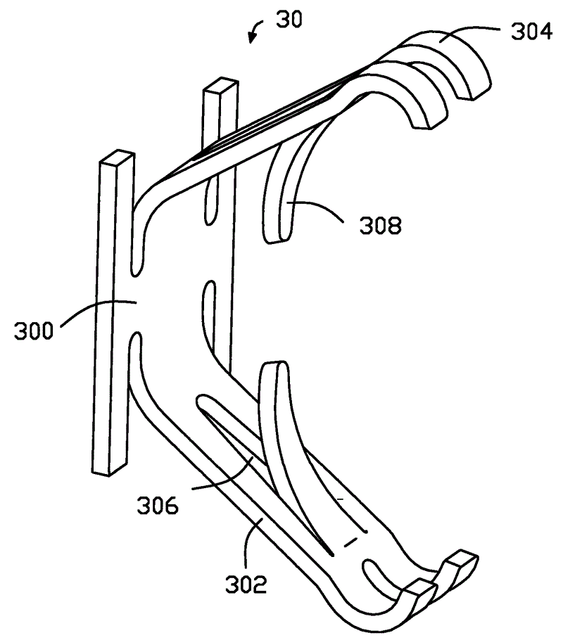
图3是本实用新型电连接器导电端子的立体示意图。Fig. 3 is a three-dimensional schematic view of the conductive terminal of the electrical connector of the present invention.
图4是图2所示的电连接器与两个电子元件的剖视图,其中导电端子尚未与电子元件接触。FIG. 4 is a cross-sectional view of the electrical connector shown in FIG. 2 and two electronic components, wherein the conductive terminals are not in contact with the electronic components.
图5类似于图4,只是导电端子已经与电子元件电性接触。FIG. 5 is similar to FIG. 4, except that the conductive terminals are in electrical contact with the electronic components.
【具体实施方式】【Detailed ways】
请参阅图1至图3,一种用来电性连接两个分离的电子元件(如,晶片模组40和印刷电路板50)的电连接器10包括设有若干端子收容槽204的绝缘本体20以及收容于上述端子收容槽204中的若干导电端子30。其中,导电端子30包括固持于端子收容槽204中的基部300以及分别自基部300上下向突出绝缘本体20方向倾斜延伸且相对设置的一对弹性臂302。每个弹性臂302在其自由末端设有多个接触点以与晶片模组40或者印刷电路板50电性连接,且每一个弹性臂302中部设有开口306,自该开口306的一端向与其相对的弹性臂302方向分别延伸出呈悬臂状的肋骨部308。Referring to FIGS. 1 to 3, an
请参阅图1、图4和图5,绝缘本体20包括与晶片模组40相对的上表面202、与印刷电路板50相对的下表面206,以及自上表面202和下表面206之间延伸的端子收容槽204。每个端子收容槽204包括贯穿的窄固持槽2040和宽收容槽2042。1, 4 and 5, the
请结合图3,导电端子30一般是由冲压而成的金属片制成,其包括H形的基部300以及自基部300上下倾斜延伸且相对设置的一对弹性臂302。该弹性臂302在其自由末端设有多个接触部(未标示)。接触部上设有不连续的接触点304。Referring to FIG. 3 , the
每一个弹性臂302中部设有开口306,且自该开口306的一端朝向与其相对的弹性臂302方向设有相对延伸且呈悬臂状的肋骨部308。该肋骨部308可经冲压或它技术而形成,在晶片模组40和印刷电路板50的作用下,该肋骨部308可彼此接触以在晶片模组40和印刷电路板50间提供较短的电性路径。Each
请参阅图2、图4和图5,当导电端子30插入至绝缘本体20的端子收容槽204时,其基部300固持于窄固持槽2040内,弹性臂302固持于宽收容槽2042中且其分别自基部300上下倾斜地凸出绝缘本体20以与晶片模组40上的导电片400和印刷电路板50上的导电元件500电性接触。Please refer to FIG. 2, FIG. 4 and FIG. 5, when the
本实用新型电连接器10导电端子30多个接触点304的设置以与晶片模组40或印刷电路板50电性连接,这样,可以提供导电端子30和晶片模组40或印刷电路板50良好的电性接触。The
请特别参阅图4和图5,初始时,导电端子30的弹性臂302处于自然状态,其两个肋骨部308相互分离,当弹性臂302被晶片模组40完全压下后,两个肋骨部308相互接触。此时,信号的传输路径为:从导电端子30与晶片模组40接触的弹性臂302的接触点304到肋骨部308再到导电端子30与印刷电路板50接触的另一弹性臂302的接触点304。换句话说,就是肋骨部308的设置提供了晶片模组40和印刷电路板50之间较短的电性路径。Please refer to FIGS. 4 and 5 in particular. Initially, the
需要指出的是,在本实施例中,弹性臂302中部的开口306以及自开口306的一端朝向与其相对的弹性臂302方向延伸的肋骨部308在一对弹性臂302上均有设置,其实,只在一个弹性臂302上设置肋骨部308也是可以的。It should be pointed out that, in this embodiment, the opening 306 in the middle of the
以上所述仅为本实用新型的一种实施方式,不是全部或唯一的实施方式,本领域普通技术人员通过阅读本实用新型说明书而对本实用新型技术方案采取的任何等效的变化,均为本实用新型的权利要求所涵盖。The above is only one embodiment of the utility model, not all or the only implementation. Any equivalent change to the technical solution of the utility model adopted by those of ordinary skill in the art by reading the specification of the utility model shall be considered as the present invention. covered by the claims of the utility model.
Claims (5)
Applications Claiming Priority (2)
| Application Number | Priority Date | Filing Date | Title |
|---|---|---|---|
| US11/492,149 US7341485B2 (en) | 2006-07-24 | 2006-07-24 | Land grid array socket |
| US11/492,149 | 2006-07-24 |
Publications (1)
| Publication Number | Publication Date |
|---|---|
| CN201097405Y true CN201097405Y (en) | 2008-08-06 |
Family
ID=38972001
Family Applications (1)
| Application Number | Title | Priority Date | Filing Date |
|---|---|---|---|
| CNU2007201256311U2007201256311U Expired - Fee Related CN201097405Y (en) | 2006-07-24 | 2007-07-24 | electrical connector |
Country Status (3)
| Country | Link |
|---|---|
| US (1) | US7341485B2 (en) |
| CN (1) | CN201097405Y (en) |
| TW (1) | TWM332273U (en) |
Cited By (8)
| Publication number | Priority date | Publication date | Assignee | Title |
|---|---|---|---|---|
| CN107968272A (en) * | 2017-01-12 | 2018-04-27 | 番禺得意精密电子工业有限公司 | Terminal |
| US10003150B1 (en) | 2017-07-14 | 2018-06-19 | Lotes Co., Ltd | Electrical connector and electronic device |
| US10116080B1 (en) | 2017-07-14 | 2018-10-30 | Lotes Co., Ltd | Electrical connector and electronic device |
| US10276953B2 (en) | 2017-05-12 | 2019-04-30 | Lotes Co., Ltd | Electrical connector |
| CN111342267A (en) * | 2018-12-19 | 2020-06-26 | 泰科电子日本合同会社 | Interposer and method of making interposer |
| US11146007B2 (en) | 2019-11-25 | 2021-10-12 | Lotes Co., Ltd. | Electrical connector and method for manufacturing the same |
| US11469533B2 (en) | 2019-01-08 | 2022-10-11 | Lotes Co., Ltd | Electrical terminal and electrical connector in vertical compression contact with chip module |
| USRE50783E1 (en) | 2019-01-08 | 2026-02-03 | Lotes Co., Ltd | Electrical terminal and electrical connector in vertical compression contact with chip module |
Families Citing this family (30)
| Publication number | Priority date | Publication date | Assignee | Title |
|---|---|---|---|---|
| CN200941464Y (en) * | 2006-06-23 | 2007-08-29 | 富士康(昆山)电脑接插件有限公司 | electrical connector |
| JP2008059810A (en) * | 2006-08-29 | 2008-03-13 | Japan Aviation Electronics Industry Ltd | Connector |
| US7692281B2 (en) * | 2007-02-16 | 2010-04-06 | Tyco Electronics Corporation | Land grid array module with contact locating features |
| JP5238928B2 (en) * | 2007-04-19 | 2013-07-17 | 並木精密宝石株式会社 | Feed terminal structure |
| JP5009190B2 (en) * | 2008-02-27 | 2012-08-22 | オリンパスメディカルシステムズ株式会社 | Electrical connector |
| TWM351483U (en) * | 2008-08-04 | 2009-02-21 | Hon Hai Prec Ind Co Ltd | Electrical connector |
| US7632156B1 (en) * | 2008-09-17 | 2009-12-15 | Cheng Uei Precision Industry Co., Ltd. | Connector and connector assembly having terminals with multiple contact areas |
| US9426918B2 (en) * | 2009-02-05 | 2016-08-23 | Oracle America, Inc. | Socket package including integrataed capacitors |
| TW201106540A (en) * | 2009-08-04 | 2011-02-16 | Hon Hai Prec Ind Co Ltd | Electrical connection device |
| CN102201623B (en) * | 2010-03-24 | 2013-03-13 | 富士康(昆山)电脑接插件有限公司 | Electric connector |
| CN201797115U (en) * | 2010-09-01 | 2011-04-13 | 富士康(昆山)电脑接插件有限公司 | Electrical connectors and their conductive terminals |
| US8287290B2 (en) * | 2011-02-08 | 2012-10-16 | General Electric Company | Device, system and method of an interface connector |
| US8672688B2 (en) * | 2012-01-17 | 2014-03-18 | International Business Machines Corporation | Land grid array interposer with compressible conductors |
| DE202012010365U1 (en) | 2012-10-29 | 2012-11-13 | Rosenberger Hochfrequenztechnik Gmbh & Co. Kg | Contact element and contact device |
| US9172161B2 (en) * | 2012-12-12 | 2015-10-27 | Amphenol InterCon Systems, Inc. | Impedance controlled LGA interposer assembly |
| JP2016046020A (en) * | 2014-08-20 | 2016-04-04 | 富士通コンポーネント株式会社 | Contact member |
| WO2016158567A1 (en) * | 2015-03-31 | 2016-10-06 | 株式会社エンプラス | Socket for electrical components, and production method therefor |
| CN109103646B (en) * | 2017-06-21 | 2021-05-25 | 富士康(昆山)电脑接插件有限公司 | Electrical connector |
| JP7142425B2 (en) * | 2017-10-23 | 2022-09-27 | タイコエレクトロニクスジャパン合同会社 | interposer assembly |
| TWI813739B (en) * | 2018-08-17 | 2023-09-01 | 英屬開曼群島商鴻騰精密科技股份有限公司 | Electrical connector |
| CN109713477B (en) * | 2018-11-28 | 2021-01-26 | 番禺得意精密电子工业有限公司 | Electrical connector |
| CN113875094A (en) | 2019-02-22 | 2021-12-31 | 安芬诺尔互连系统股份有限公司 | Connector assembly and method |
| JP7427382B2 (en) * | 2019-07-23 | 2024-02-05 | タイコエレクトロニクスジャパン合同会社 | interposer |
| CN111064025B (en) * | 2019-07-23 | 2021-05-25 | 番禺得意精密电子工业有限公司 | Electrical connector |
| CN211605463U (en) * | 2020-01-07 | 2020-09-29 | 番禺得意精密电子工业有限公司 | Electrical connector |
| TWM602744U (en) * | 2020-01-20 | 2020-10-11 | 唐虞企業股份有限公司 | Forced mechanism and connector constituted of the same |
| US20230178286A1 (en) * | 2020-06-19 | 2023-06-08 | Murata Manufacturing Co., Ltd. | Surface-mount-assembly z-shaped pin |
| US12051865B2 (en) * | 2021-12-28 | 2024-07-30 | Te Connectivity Solutions Gmbh | Socket connector |
| TWI828079B (en) * | 2022-03-16 | 2024-01-01 | 唐虞企業股份有限公司 | Electrical connector, conductive terminals and manufacturing method thereof |
| CN116667013A (en) * | 2023-05-30 | 2023-08-29 | 立讯精密工业股份有限公司 | Board-to-Board Connector |
Family Cites Families (5)
| Publication number | Priority date | Publication date | Assignee | Title |
|---|---|---|---|---|
| JPH11250966A (en) * | 1997-12-22 | 1999-09-17 | Whitaker Corp:The | connector |
| FR2809871B1 (en) * | 2000-06-05 | 2002-07-19 | Itt Mfg Entpr S Inc | ELECTRICAL CONNECTOR WITH IMPROVED CONTACT BLADES FOR CONNECTION OF AN INTEGRATED CIRCUIT (S) CARD |
| SG104969A1 (en) * | 2002-05-24 | 2004-07-30 | Fci Asia Technology Pte Ltd | An electrical connector |
| TWI282645B (en) * | 2004-04-16 | 2007-06-11 | Hon Hai Prec Ind Co Ltd | Electrical contact |
| TWM262874U (en) * | 2004-08-10 | 2005-04-21 | Starlink Electronics Corp | LGA terminal structure with changed circuit |
-
2006
- 2006-07-24 US US11/492,149 patent/US7341485B2/en not_active Expired - Fee Related
-
2007
- 2007-07-24 TW TW096212071U patent/TWM332273U/en unknown
- 2007-07-24 CN CNU2007201256311U2007201256311U patent/CN201097405Y/en not_active Expired - Fee Related
Cited By (12)
| Publication number | Priority date | Publication date | Assignee | Title |
|---|---|---|---|---|
| CN107968272A (en) * | 2017-01-12 | 2018-04-27 | 番禺得意精密电子工业有限公司 | Terminal |
| CN108110455A (en) * | 2017-01-12 | 2018-06-01 | 番禺得意精密电子工业有限公司 | Electric connector |
| CN107968272B (en) * | 2017-01-12 | 2019-08-30 | 番禺得意精密电子工业有限公司 | Terminal |
| CN108110455B (en) * | 2017-01-12 | 2020-08-28 | 番禺得意精密电子工业有限公司 | Electrical connector |
| US10276953B2 (en) | 2017-05-12 | 2019-04-30 | Lotes Co., Ltd | Electrical connector |
| US10003150B1 (en) | 2017-07-14 | 2018-06-19 | Lotes Co., Ltd | Electrical connector and electronic device |
| US10116080B1 (en) | 2017-07-14 | 2018-10-30 | Lotes Co., Ltd | Electrical connector and electronic device |
| CN111342267A (en) * | 2018-12-19 | 2020-06-26 | 泰科电子日本合同会社 | Interposer and method of making interposer |
| CN111342267B (en) * | 2018-12-19 | 2024-05-28 | 泰科电子日本合同会社 | Interposer and method for manufacturing interposer |
| US11469533B2 (en) | 2019-01-08 | 2022-10-11 | Lotes Co., Ltd | Electrical terminal and electrical connector in vertical compression contact with chip module |
| USRE50783E1 (en) | 2019-01-08 | 2026-02-03 | Lotes Co., Ltd | Electrical terminal and electrical connector in vertical compression contact with chip module |
| US11146007B2 (en) | 2019-11-25 | 2021-10-12 | Lotes Co., Ltd. | Electrical connector and method for manufacturing the same |
Also Published As
| Publication number | Publication date |
|---|---|
| US7341485B2 (en) | 2008-03-11 |
| US20080020638A1 (en) | 2008-01-24 |
| TWM332273U (en) | 2008-05-11 |
Similar Documents
| Publication | Publication Date | Title |
|---|---|---|
| CN109103646B (en) | Electrical connector | |
| US8079879B2 (en) | Receptacle connector for dual signal transmission protocol | |
| TWM332273U (en) | Board-to-board connector with grounding member | |
| CN201097406Y (en) | electrical connector | |
| US6565366B1 (en) | Electrical connector | |
| CN101212098B (en) | electrical connector terminal | |
| US20100035488A1 (en) | Contact terminal having receiving arms arranged to provide robust receiving space therebetween | |
| US7891991B2 (en) | Contact having soldered interconnection between first and second parts | |
| CN100470964C (en) | Electric connector | |
| CN201266708Y (en) | Electric connector terminal | |
| TWM399510U (en) | Electrical connector | |
| CN200941464Y (en) | electrical connector | |
| CN201142393Y (en) | electrical connector | |
| CN200941505Y (en) | electrical connector | |
| CN218123754U (en) | Electrical connection components and electrical connection devices | |
| CN100555767C (en) | Electric connector and manufacture method thereof | |
| US7134920B1 (en) | Electrical module chip connector | |
| JP3156557U (en) | Conductive terminal and electrical connector using the same | |
| CN202076441U (en) | Conductive terminal | |
| CN201112663Y (en) | Electric connector | |
| CN100355152C (en) | Electric connector | |
| CN201601290U (en) | electrical connector terminal | |
| CN201266781Y (en) | Electric connector | |
| CN113904140B (en) | Terminal, terminal assembly and electrical connector | |
| CN216648685U (en) | Front-lifting type connector for flexible printed circuit |
Legal Events
| Date | Code | Title | Description |
|---|---|---|---|
| C14 | Grant of patent or utility model | ||
| GR01 | Patent grant | ||
| C17 | Cessation of patent right | ||
| CF01 | Termination of patent right due to non-payment of annual fee |
Granted publication date: 20080806 |