CN201096705Y - Variable-capacity water-volume container based on fluid comprehensive compressibility - Google Patents
Variable-capacity water-volume container based on fluid comprehensive compressibility Download PDFInfo
- Publication number
- CN201096705Y CN201096705Y CNU2007200875992U CN200720087599U CN201096705Y CN 201096705 Y CN201096705 Y CN 201096705Y CN U2007200875992 U CNU2007200875992 U CN U2007200875992U CN 200720087599 U CN200720087599 U CN 200720087599U CN 201096705 Y CN201096705 Y CN 201096705Y
- Authority
- CN
- China
- Prior art keywords
- container
- fluid
- liquid
- compressibility
- gas
- Prior art date
- Legal status (The legal status is an assumption and is not a legal conclusion. Google has not performed a legal analysis and makes no representation as to the accuracy of the status listed.)
- Expired - Fee Related
Links
Images


Landscapes
- Investigating Strength Of Materials By Application Of Mechanical Stress (AREA)
- Investigation Of Foundation Soil And Reinforcement Of Foundation Soil By Compacting Or Drainage (AREA)
Abstract
本实用新型公开了一种基于流体综合压缩性可调的变容水量容器,涉及一种替代瞬态压力脉冲法测量岩石流体渗透系数实验装置中的水箱。包括进/出液口(1)、筒身(2)、液体腔(3)、分隔膜(4)、螺栓(5)、气体腔(6)、密封圈(7)、底盖(8)和进/出气口(9);从上到下,筒身(2)、密封圈(7)和底盖(8)通过螺栓(5)连接为一个密封的容器,在容器内设置有分隔膜(4)并形成液体腔(3)和气体腔(6);在筒身(2)的顶部设置有进/出液口(1),在底盖(8)下面设置有进/出气口(9)。本实用新型可实现优化试验装置,扩大测量范围,加快试验速度,提高实验精度的目的。
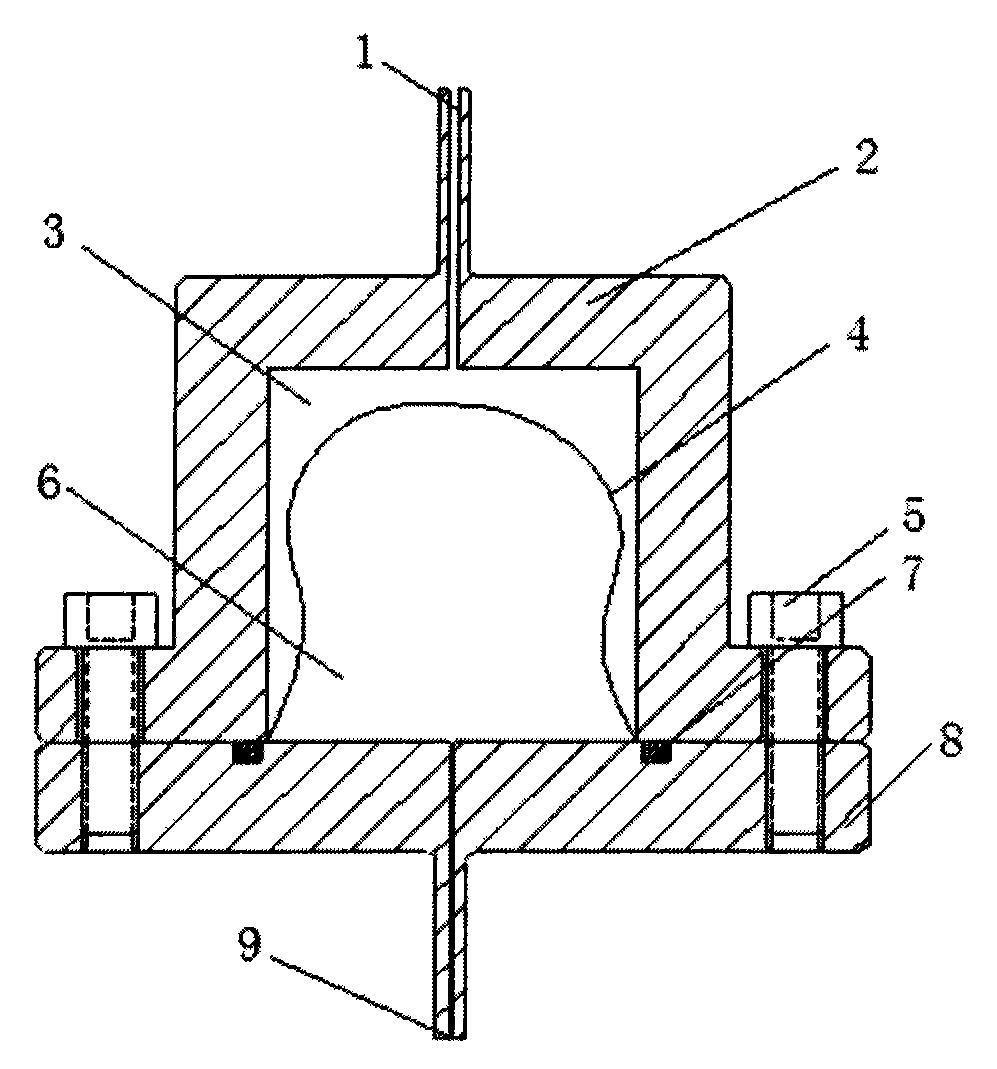
The utility model discloses a variable capacity water container based on fluid comprehensive compressibility and relates to a water tank in an experimental device for measuring rock fluid permeability coefficient instead of a transient pressure pulse method. Including liquid inlet/outlet (1), cylinder body (2), liquid chamber (3), separation membrane (4), bolts (5), gas chamber (6), sealing ring (7), bottom cover (8) and air inlet/outlet (9); from top to bottom, the cylinder body (2), sealing ring (7) and bottom cover (8) are connected by bolts (5) to form a sealed container, and a separation film is arranged in the container (4) and form a liquid chamber (3) and a gas chamber (6); the top of the cylinder body (2) is provided with an inlet/outlet port (1), and the bottom cover (8) is provided with an inlet/outlet port ( 9). The utility model can realize the purposes of optimizing the test device, enlarging the measuring range, speeding up the test speed and improving the test precision.
Description
技术领域technical field
本实用新型涉及一种替代瞬态压力脉冲法测量岩石流体渗透系数实验装置中的水箱;具体地说,主要是针对实验室内瞬态压力脉冲法测量岩石渗透系数的实验装置进行优化改进;改进后,容器内流体综合压缩性可调,且可调整至所需的大小,从而实现岩石流体渗透系数快速精确地测量。The utility model relates to a water tank in an experimental device for measuring the rock fluid permeability coefficient by a transient pressure pulse method; specifically, it mainly aims at optimizing and improving the experimental device for measuring the rock permeability coefficient by the transient pressure pulse method in the laboratory; the improvement Finally, the comprehensive compressibility of the fluid in the container is adjustable, and can be adjusted to the required size, so as to realize the rapid and accurate measurement of the rock fluid permeability coefficient.
背景技术Background technique
渗透性是孔隙和裂隙介质的一种重要性质。近年来,由于低渗透油气田的开发、放射性物质的地下存埋及二氧化碳等温室气体的地中隔离等重大工程问题的研究,迫切需要对具有较低渗透系数的天然和人工材料在复杂地质条件下的长期渗透性能有进一步了解。实验室内渗透测量方法有常水头法和变水头法,其中对于低渗透测量方法主要为变水头法。变水头法主要有恒流泵法、压力振荡法和压力脉冲法。实践表明:压力脉冲法因其理论成熟,操作容易,而应用较为广泛。但实际的测量精度很大程度上取决于测量系统的设计、制作和操作程序是否合理。Permeability is an important property of porous and fractured media. In recent years, due to the research on major engineering issues such as the development of low-permeability oil and gas fields, underground storage of radioactive substances, and underground isolation of greenhouse gases such as carbon dioxide, there is an urgent need to study natural and artificial materials with low permeability coefficients under complex geological conditions. The long-term penetration performance has a further understanding. There are constant water head method and variable water head method in laboratory infiltration measurement method, among which the variable water head method is mainly used for low permeability measurement method. The variable head method mainly includes constant flow pump method, pressure oscillation method and pressure pulse method. Practice shows that the pressure pulse method is widely used because of its mature theory and easy operation. However, the actual measurement accuracy largely depends on whether the design, production and operation procedures of the measurement system are reasonable.
瞬态压力脉冲法首先由Brace等于1968年提出并用于测量Westerly花岗岩的渗透系数,其实验原理如图6,试件(B)两端分别连接一个大小形状一定的上游水箱(A)和下游水箱(C),水箱内注满水,水的压缩性已知且不可变;水箱容积已知,由此可计算出水箱内流体容水量的大小,为一定值不可变。该实验只能得到渗透系数的近似解,且在水箱容水量不可改变的情况下,该试验的测量范围也具有一定的局限性,一般测量两个数量级范围内岩石流体渗透系数较准确。The transient pressure pulse method was first proposed by Brace et al. in 1968 and used to measure the permeability coefficient of Westerly granite. The experimental principle is shown in Figure 6. The two ends of the specimen (B) are respectively connected to an upstream water tank (A) and a downstream water tank with a certain size and shape. (C), the water tank is filled with water, and the compressibility of the water is known and invariable; the volume of the water tank is known, so the water capacity of the fluid in the water tank can be calculated, which is a certain value and invariable. This experiment can only obtain an approximate solution of the permeability coefficient, and in the case that the water capacity of the water tank cannot be changed, the measurement range of this experiment also has certain limitations. Generally, it is more accurate to measure the permeability coefficient of rock fluid within the range of two orders of magnitude.
此后,众多的研究者致力于求解渗透系数计算方法上的突破,Hsieh等给出了基于水头表达的渗流基本方程和无穷级数形式的解析解。Neuzi等提出了求解渗透系数和比贮留系数的图解方法。但是这些方法的主要问题是比较繁琐并易产生人为误差。Zhang M等提出了反分析的方法,该方法比图解法方便,并消除了人为任意性。Since then, many researchers have devoted themselves to solving the breakthrough in the calculation method of the permeability coefficient. Hsieh et al. have given the basic seepage equation based on the expression of water head and the analytical solution in the form of infinite series. Neuzi et al. proposed a graphical method for solving the permeability coefficient and specific retention coefficient. But the main problem of these methods is that they are cumbersome and prone to human errors. Zhang M et al. proposed an anti-analysis method, which is more convenient than the graphical method and eliminates artificial arbitrariness.
但是,截至现在,此类测量系统中的关键装置——水箱并没有实质性的改变。对于测量渗透性较低的岩石,用现有的实验装置将需要很长的时间,且测量结果误差较大。所以目前采用瞬态压力脉冲法的实验装置对于测量岩石流体渗透系数的适用范围非常狭窄。若要得到高精度的测量结果,在系统设计、装置制作和试验操作上还有很多需要注意和改进的地方。However, as of now, the key device in this type of measurement system, the water tank, has not changed substantially. For the measurement of rocks with low permeability, it will take a long time to use the existing experimental equipment, and the error of the measurement results is relatively large. Therefore, the current experimental devices using the transient pressure pulse method have a very narrow scope of application for measuring the permeability coefficient of rock fluids. In order to obtain high-precision measurement results, there are still many points to be noticed and improved in system design, device fabrication and test operation.
另外,在目前采用瞬态压力脉冲法实验装置,每次测量渗透系数跨越两个量级的岩石时都需要重新拆装,换成容水量大小较合适的水箱。容水量定义为容器内单位压力变化引起的流体体积改变量。传统瞬态压力脉冲法测量装置中水箱容水量与水箱容积成线性关系,在每一个既定容积水箱装置中只能测量两个量级范围内的渗透系数,所得到的测量结果误差在可接受范围内。因此,目前采用的瞬态压力脉冲法实验装置,需要配备不同容量的水箱,而且每次拆装都会引进更多的误差,从而影响测量结果。此外,以增大容器容积的方式增大容水量导致装置笨重和制造成本增加。In addition, the current experimental device using the transient pressure pulse method needs to be disassembled and replaced with a water tank with a suitable water capacity every time the rock whose permeability coefficient exceeds two orders of magnitude is measured. Water holding capacity is defined as the volume change of fluid caused by the change of unit pressure in the container. In the traditional transient pressure pulse method measurement device, the water capacity of the water tank has a linear relationship with the volume of the water tank. In each water tank device with a given volume, only the permeability coefficient within two orders of magnitude can be measured, and the error of the obtained measurement results is within an acceptable range. Inside. Therefore, the current transient pressure pulse method experimental device needs to be equipped with water tanks of different capacities, and each disassembly will introduce more errors, thereby affecting the measurement results. In addition, increasing the water holding capacity by increasing the volume of the container results in a bulky device and increased manufacturing costs.
基于目前采用传统瞬态压力脉冲法的测量装置的局限性,研究测量范围更广,测量精度更高的实验装置,具有非常重要的意义。Based on the limitations of the current measurement devices using the traditional transient pressure pulse method, it is of great significance to study experimental devices with wider measurement range and higher measurement accuracy.
发明内容Contents of the invention
本实用新型的目的就是为了克服现有技术存在的上述缺点和不足,提供一种基于流体综合压缩性可变的变容水量容器(简称容器),是一种替代采用瞬态压力脉冲法测量岩石流体渗透系数实验装置中的水箱。The purpose of this utility model is to overcome the above-mentioned shortcomings and deficiencies existing in the prior art, and to provide a variable-capacity water volume container (container for short) based on the variable comprehensive compressibility of the fluid, which is an alternative to the transient pressure pulse method for measuring rocks. The water tank in the experimental setup for fluid permeability coefficient.
本实用新型的目的是这样实现的:The purpose of this utility model is achieved in that:
如图1,本实用新型包括进/出液口(1)、筒身(2)、液体腔(3)、分隔膜(4)、螺栓(5)、气体腔(6)、密封圈(7)、底盖(8)和进/出气口(9);As shown in Figure 1, the utility model includes a liquid inlet/outlet (1), a barrel body (2), a liquid chamber (3), a separation film (4), a bolt (5), a gas chamber (6), a sealing ring (7) ), bottom cover (8) and air inlet/outlet (9);
从上到下,筒身(2)、密封圈(7)和底盖(8)通过螺栓(5)连接为一个密封的容器,在容器内设置有分隔膜(4)并形成液体腔(3)和气体腔(6);在筒身(2)的顶部设置有进/出液口(1),在底盖(8)下面设置有进/出气口(9)。From top to bottom, the cylinder body (2), sealing ring (7) and bottom cover (8) are connected by bolts (5) to form a sealed container, and a separation membrane (4) is arranged in the container to form a liquid chamber (3 ) and a gas chamber (6); a liquid inlet/outlet (1) is arranged on the top of the cylinder body (2), and an inlet/outlet (9) is arranged under the bottom cover (8).
本实用新型工作原理:The working principle of the utility model:
利用气体和液体的压缩系数量级相差较大,气体压缩性很大,液体压缩性很小的物理特性。将气体和液体同时置于同一容器内,通过分隔膜(4)将其隔开,而不会互相混合或溶解,以免影响容器内流体综合压缩性的计量。如果气液混合溶解,一来无法准确量化其混合后的压缩性,二来混合后的压缩性变化范围减小,所以必须要采用分隔膜(4)将气液隔开。具体地说,通过进/出液口(1)进液,进/出气口(9)出气,使得容器内液体体积增加,气体体积减少,从而降低了气液体积比,降低了容器内流体综合压缩性,压缩系数减小,容器容水量减小;同理,若增大气体体积,减少液体体积,即提高气液体积比,则容器内流体综合压缩性增加,压缩系数增大,容器容水量增大。The physical characteristic that the compressibility of the gas and the liquid is quite different in order of magnitude, the compressibility of the gas is very large, and the compressibility of the liquid is very small. The gas and the liquid are placed in the same container at the same time, separated by the separation membrane (4), and will not mix or dissolve each other, so as not to affect the measurement of the comprehensive compressibility of the fluid in the container. If the gas and liquid are mixed and dissolved, firstly, the compressibility after mixing cannot be accurately quantified, and secondly, the variation range of the compressibility after mixing is reduced, so a separation membrane (4) must be used to separate the gas and liquid. Specifically, liquid enters through the liquid inlet/outlet port (1) and gas exits through the air inlet/outlet port (9), so that the volume of the liquid in the container increases and the volume of the gas decreases, thereby reducing the gas-liquid volume ratio and reducing the overall volume of the fluid in the container. Compressibility, the compression coefficient decreases, and the water capacity of the container decreases; similarly, if the gas volume is increased and the liquid volume is reduced, that is, the gas-liquid volume ratio is increased, the comprehensive compressibility of the fluid in the container increases, the compression coefficient increases, and the container capacity increases. The amount of water increases.
整个过程实现了在不拆装调换不同体积水箱容器条件下,在不影响试验整体性和操作连续性条件下,水箱容水量可根据试验需求随意调整,直至合适大小。The whole process realizes that the water capacity of the water tank can be adjusted at will according to the test requirements until it reaches the appropriate size without disassembling and replacing the water tank containers of different volumes, without affecting the integrity of the test and the continuity of operation.
本实用新型具有以下优点和积极效果:The utility model has the following advantages and positive effects:
①在试验过程中,可实时调整改变容器内气液体积比,从而改变容器内流体综合压缩性,即改变容器容水量;① During the test, the gas-liquid volume ratio in the container can be adjusted in real time, thereby changing the comprehensive compressibility of the fluid in the container, that is, changing the water capacity of the container;
②试验原理直观、结构简单、精度高、效率高、稳定性好、易于操作、无需拆卸。②The test principle is intuitive, simple in structure, high in precision, high in efficiency, good in stability, easy to operate, and does not need to be disassembled.
③能根据不同岩石试件流体渗透系数测量需要,实现整个试验过程中只用一个水箱容器,从而有效地节省人力、物力和财力。③ According to the measurement needs of fluid permeability coefficient of different rock specimens, only one water tank container can be used in the whole test process, thus effectively saving manpower, material resources and financial resources.
④不仅便于试验操作,也避免了拆装调换不同体积水箱后,需要再次抽真空,再次注水,再次检查系统泄漏,再次标定等繁琐程序。④It is not only convenient for the test operation, but also avoids tedious procedures such as vacuuming again, refilling water, rechecking the system for leakage, and recalibrating after disassembling and replacing water tanks of different volumes.
总之,本实用新型可替代瞬态压力脉冲法测量岩石渗透系数试验装置中的水箱装置,实现优化试验装置,扩大测量范围,加快试验速度,提高实验精度的目的。In a word, the utility model can replace the water tank device in the test device for measuring the rock permeability coefficient by the transient pressure pulse method, realize the purpose of optimizing the test device, expanding the measurement range, speeding up the test speed and improving the test accuracy.
附图说明Description of drawings
图1是本实用新型结构示意图;Fig. 1 is a structural representation of the utility model;
图2是分隔膜结构示意图;Fig. 2 is a schematic diagram of the separation membrane structure;
图3是筒身结构示意图;Fig. 3 is a schematic view of the barrel structure;
图4是底盖结构示意图(主视);Fig. 4 is a schematic view of the structure of the bottom cover (front view);
图5是底盖结构示意图(俯视);Fig. 5 is a schematic view of the structure of the bottom cover (top view);
图6是传统瞬态压力脉冲法原理图。Figure 6 is a schematic diagram of the traditional transient pressure pulse method.
其中:in:
1-进/出液口; 2-筒身; 3-液体腔;1-in/out liquid port; 2-cylinder body; 3-liquid cavity;
4-分隔膜; 5-螺栓; 6-气体腔;4-separation membrane; 5-bolt; 6-gas cavity;
7-密封圈; 8-底盖; 9-进/出气口;7-sealing ring; 8-bottom cover; 9-inlet/outlet port;
A-上游水箱; B-试件; C-下游水箱。A-upstream water tank; B-test piece; C-downstream water tank.
具体实施方式Detailed ways
下面结合附图和实施示例对本实用新型进一步说明:Below in conjunction with accompanying drawing and implementation example the utility model is further described:
一、各部件的结构1. The structure of each component
1、分隔膜(4)1. Separator (4)
如图1、2,分隔膜(4)为一种由整体成膜工艺形成的可自由变形、不易断裂的圆筒形薄膜;薄膜材质可为:聚四氟乙烯、聚氯乙烯等塑料。As shown in Figures 1 and 2, the separation film (4) is a freely deformable, non-breakable cylindrical film formed by an integral film forming process; the film material can be: polytetrafluoroethylene, polyvinyl chloride and other plastics.
分隔膜(4)将容器分隔成两个腔:液体腔(3)和气体腔(6);随着气液体积比的变化,分隔膜(4)在容器内的形状也在不断变化;The separation film (4) separates the container into two chambers: the liquid chamber (3) and the gas chamber (6); as the gas-liquid volume ratio changes, the shape of the separation film (4) in the container is also constantly changing;
分隔膜(4)内置于筒身(2)内,分隔膜(4)的裙边被夹紧固定在筒身(2)和底盖(8)之间。The separation membrane (4) is built in the cylinder body (2), and the skirt of the separation membrane (4) is clamped and fixed between the cylinder body (2) and the bottom cover (8).
2、筒身(2)2. Barrel (2)
如图1、3,筒身(2)是一种采用通用压力容器形成方法制作成的容器;As shown in Fig. 1, 3, cylinder body (2) is a kind of container that adopts general pressure container forming method to make;
进/出液口(1)设在筒身(2)的上端。The liquid inlet/outlet (1) is arranged on the upper end of the cylinder body (2).
3、底盖(8)3. Bottom cover(8)
如图1、4、5,底盖(8)是一种采用通用压力容器形成方法制作成的盖板;As shown in Figures 1, 4, and 5, the bottom cover (8) is a cover plate made of a general pressure vessel forming method;
下进/出气口(9)设在底盖(8)的下端。The lower air inlet/outlet (9) is located at the lower end of the bottom cover (8).
4、密封圈(7)4. Sealing ring (7)
如图1、4、5,密封圈(7)嵌固于底盖(8)上板面的凹槽内;用于密封分隔膜(4)的裙边。As shown in Figures 1, 4, and 5, the sealing ring (7) is embedded in the groove on the upper surface of the bottom cover (8); it is used to seal the skirt of the separation membrane (4).
5、螺栓(5)5. Bolts (5)
如图1,螺栓(5)为常用件,连接筒身(2)和底盖(8),用于紧固密封整个容器。As shown in Figure 1, the bolt (5) is a common part, which connects the cylinder body (2) and the bottom cover (8), and is used to fasten and seal the entire container.
二、使用方法2. How to use
1、整个容器抽真空后,通过进/出液口(1)注入液体(如水)至液体腔(3)内,注满整个容器;对整个容器施加基压,排除液体腔(3)内的蒸汽。1. After the entire container is evacuated, inject liquid (such as water) into the liquid chamber (3) through the liquid inlet/outlet port (1) to fill the entire container; apply base pressure to the entire container to remove the liquid in the liquid chamber (3) steam.
2、整个容器施加基压排气后,通过进/出气口(9)注入气体(如空气)至气体腔(6)内,注入适当体积。2. After the base pressure is applied to the entire container to exhaust, inject gas (such as air) into the gas chamber (6) through the inlet/outlet port (9), and inject an appropriate volume.
3、注入气体时,气体腔(6)体积增大,分隔膜(4)胀开,液体腔(3)体积减小,部分液体通过进/出液口(1)排出容器;量测排出液体之质量可换算得所注入气体的体积。3. When gas is injected, the volume of the gas chamber (6) increases, the separation membrane (4) expands, the volume of the liquid chamber (3) decreases, and part of the liquid is discharged from the container through the liquid inlet/outlet port (1); measure the discharged liquid The mass can be converted to the volume of injected gas.
三、容器内流体综合容水量的计量3. Measurement of the comprehensive water capacity of the fluid in the container
流体容水量计量公式为:The fluid water capacity measurement formula is:
Cs=(Cw·Vw+Cg·Vg)/Vs (1)C s =(C w ·V w +C g ·V g )/V s (1)
Vs=Vw+Vg (2)V s =V w +V g (2)
其中:in:
Cs-流体综合压缩系数;C s -Comprehensive compressibility coefficient of fluid;
Cw-液体压缩系数;C w - liquid compressibility;
Cg-气体压缩系数;C g - gas compressibility;
Vs-容器体积;V s - vessel volume;
Vw-液体体积;V w - liquid volume;
Vg-气体体积。V g - gas volume.
容器体积已知,通过注气排液,量测排出液体质量换算得注入气体的体积,从而可得容器内液体和气体的体积;液体和气体的压缩系数目前有现成可靠的数据可用;此时,将各数据代入以上公式可得到容器内流体综合压缩系数Cs。由此可见,通过调节容器内气体体积的大小,就可以改变容器内流体综合压缩性大小。The volume of the container is known, and the volume of the injected gas can be converted by measuring the mass of the discharged liquid through gas injection and liquid discharge, so as to obtain the volume of the liquid and gas in the container; the compressibility coefficients of liquid and gas are currently available and reliable data are available; at this time , Substituting each data into the above formula can get the comprehensive compressibility coefficient C s of the fluid in the container. It can be seen that by adjusting the size of the gas volume in the container, the comprehensive compressibility of the fluid in the container can be changed.
Claims (2)
Priority Applications (1)
| Application Number | Priority Date | Filing Date | Title |
|---|---|---|---|
| CNU2007200875992U CN201096705Y (en) | 2007-10-18 | 2007-10-18 | Variable-capacity water-volume container based on fluid comprehensive compressibility |
Applications Claiming Priority (1)
| Application Number | Priority Date | Filing Date | Title |
|---|---|---|---|
| CNU2007200875992U CN201096705Y (en) | 2007-10-18 | 2007-10-18 | Variable-capacity water-volume container based on fluid comprehensive compressibility |
Publications (1)
| Publication Number | Publication Date |
|---|---|
| CN201096705Y true CN201096705Y (en) | 2008-08-06 |
Family
ID=39923758
Family Applications (1)
| Application Number | Title | Priority Date | Filing Date |
|---|---|---|---|
| CNU2007200875992U Expired - Fee Related CN201096705Y (en) | 2007-10-18 | 2007-10-18 | Variable-capacity water-volume container based on fluid comprehensive compressibility |
Country Status (1)
| Country | Link |
|---|---|
| CN (1) | CN201096705Y (en) |
Cited By (4)
| Publication number | Priority date | Publication date | Assignee | Title |
|---|---|---|---|---|
| CN104390863A (en) * | 2014-11-25 | 2015-03-04 | 河海大学 | Flexible impervious body joint structure hydraulic dynamic tester and test method |
| CN107703040A (en) * | 2017-09-19 | 2018-02-16 | 南京工程学院 | A kind of diaphragm type hydraulic pressure clamps rubber seal concrete impermeability test device |
| CN108291687A (en) * | 2015-11-25 | 2018-07-17 | 爱斯卡润特能源公司 | variable pressure container |
| CN110748635A (en) * | 2019-10-28 | 2020-02-04 | 江苏众力合创精密机械科技有限公司 | Efficient planetary gear reducer |
-
2007
- 2007-10-18 CN CNU2007200875992U patent/CN201096705Y/en not_active Expired - Fee Related
Cited By (6)
| Publication number | Priority date | Publication date | Assignee | Title |
|---|---|---|---|---|
| CN104390863A (en) * | 2014-11-25 | 2015-03-04 | 河海大学 | Flexible impervious body joint structure hydraulic dynamic tester and test method |
| CN104390863B (en) * | 2014-11-25 | 2017-02-01 | 河海大学 | Flexible impervious body joint structure hydraulic dynamic tester and test method |
| CN108291687A (en) * | 2015-11-25 | 2018-07-17 | 爱斯卡润特能源公司 | variable pressure container |
| CN108291687B (en) * | 2015-11-25 | 2021-03-16 | 爱斯卡润特能源公司 | Variable pressure vessel |
| CN107703040A (en) * | 2017-09-19 | 2018-02-16 | 南京工程学院 | A kind of diaphragm type hydraulic pressure clamps rubber seal concrete impermeability test device |
| CN110748635A (en) * | 2019-10-28 | 2020-02-04 | 江苏众力合创精密机械科技有限公司 | Efficient planetary gear reducer |
Similar Documents
| Publication | Publication Date | Title |
|---|---|---|
| CN110907334B (en) | Device and method for measuring radial flow oil-water relative permeability of conglomerate full-diameter core | |
| CN201532351U (en) | A device for testing rock gas permeability coefficient by variable volume pressure pulse method | |
| CN201732048U (en) | Porous concrete water permeability testing instrument | |
| CN104833618B (en) | To heterogeneous reservoir simulate the method and apparatus of profile control in laboratory | |
| CN106970000A (en) | Coal/shale extra-high absorption and Seepage Experiment evaluate shale gas adsorption method | |
| CN104897543A (en) | Multi-phase permeameter and rock permeability determination method | |
| CN111706321A (en) | An experimental device for multi-layer commingled mining of coalbed methane | |
| CN107063968B (en) | Concrete gas permeability testing device and method | |
| CN206223619U (en) | A kind of permeability coefficient of cement soil tester | |
| CN108316916A (en) | Mining pressure drop under different conditions of coal bed gas reservoir controls simulation experiment method | |
| CN107807084A (en) | A kind of rock sample seepage flow test device and method | |
| CN104764824A (en) | Device and method for measuring concentration distribution of CO2 soluble surfactant in CO2/water system during one-dimensional seepage | |
| CN102865899B (en) | High Temperature High Pressure rock core displacement process medium fluid volume in-situ measuring method and device thereof | |
| CN109765160A (en) | A kind of apparatus for unsaturated seepage experiment of rock cranny | |
| CN101382480A (en) | a variable volume container | |
| CN108169098A (en) | The reasonable mining speed simulator of coal bed gas straight well single-phase flow | |
| CN209182187U (en) | A CO2 flooding experimental device | |
| CN205719852U (en) | CO2 replacement shale gas and shale adsorption analysis simulation test device for shale gas or CO2 | |
| CN116537753A (en) | CO utilization 2 Multifunctional displacement system and method | |
| CN205103133U (en) | Bentonite infiltration coefficient measurement appearance | |
| CN206656946U (en) | Concrete gas testing permeability device | |
| CN108181440B (en) | An experimental device for testing the water quality index of reinjection water in large-scale underground water-sealed caves | |
| CN207832632U (en) | The reasonable mining speed simulator of coal bed gas straight well single-phase flow | |
| CN209103628U (en) | A kind of reynolds test instrument | |
| CN207019739U (en) | A kind of device for determining irregular seal cavity volume |
Legal Events
| Date | Code | Title | Description |
|---|---|---|---|
| C14 | Grant of patent or utility model | ||
| GR01 | Patent grant | ||
| C17 | Cessation of patent right | ||
| CF01 | Termination of patent right due to non-payment of annual fee |
Granted publication date: 20080806 Termination date: 20131018 |