CN201061985Y - Laminated six-link wheel-assembly hollow axle device - Google Patents
Laminated six-link wheel-assembly hollow axle device Download PDFInfo
- Publication number
- CN201061985Y CN201061985Y CNU2007201493020U CN200720149302U CN201061985Y CN 201061985 Y CN201061985 Y CN 201061985Y CN U2007201493020 U CNU2007201493020 U CN U2007201493020U CN 200720149302 U CN200720149302 U CN 200720149302U CN 201061985 Y CN201061985 Y CN 201061985Y
- Authority
- CN
- China
- Prior art keywords
- wheel
- hollow shaft
- connecting rod
- stacked
- connecting rods
- Prior art date
- Legal status (The legal status is an assumption and is not a legal conclusion. Google has not performed a legal analysis and makes no representation as to the accuracy of the status listed.)
- Expired - Fee Related
Links
Images

Landscapes
- Shafts, Cranks, Connecting Bars, And Related Bearings (AREA)
Abstract
本实用新型涉及一种叠片式六连杆轮对空心轴装置,具有套置在车轴上的空心轴,在所述车轴的两端固定有车轮,所述空心轴的两端分别设有一传动盘,其中一传动盘与驱动齿轮相连接,另一传动盘与固定在所述车轴一端的车轮相连接,其特征在于:所述传动盘与驱动齿轮、传动盘与车轮之间分别通过六个连杆相连接,所述连杆为由多个金属薄片层叠构成的叠片式连杆,每一叠片式连杆的一端与所述传动盘相连接,另一端与所述驱动齿轮或车轮相连接。本实用新型克服了公知的橡胶关节式连接结构的缺陷,减小了六连杆的结构尺寸,降低了簧下重量,从而提高了机车的动力学性能。且易于拆装,实现了机车转向架的更优化设计和免维护,降低了制造成本,节约设计空间。
The utility model relates to a hollow shaft device of a laminated six-link wheel set, which has a hollow shaft sleeved on the axle, wheels are fixed at both ends of the axle, and a transmission drive is respectively arranged at the two ends of the hollow shaft. One of the transmission discs is connected with the driving gear, and the other transmission disc is connected with the wheel fixed at one end of the axle. Connecting rods are connected, and the connecting rods are laminated connecting rods composed of a plurality of laminated metal sheets. One end of each laminated connecting rod is connected to the transmission disc, and the other end is connected to the driving gear or wheel. connected. The utility model overcomes the defects of the known rubber articulated connection structure, reduces the structural size of the six-link rod, reduces the unsprung weight, and thus improves the dynamic performance of the locomotive. And it is easy to disassemble and assemble, realizes the more optimized design and maintenance-free of the locomotive bogie, reduces the manufacturing cost, and saves the design space.
Description
技术领域 technical field
本实用新型涉及到一种机车转向架的六连杆轮对空心轴传动装置,特别是一种叠片式六连杆轮对空心轴装置。The utility model relates to a six-link wheel pair hollow shaft transmission device of a locomotive bogie, in particular to a laminated six-link wheel pair hollow shaft device.
背景技术 Background technique
目前,公知的机车转向架的六连杆轮对空心轴传动装置,为橡胶关节式的六连杆轮对空心轴装置,主要由轮对(车轮和车轴)、齿轮、空心轴、连杆销、橡胶关节、连杆、传力销、传动盘、压盖、止动垫等主要部件组成。At present, the known six-link wheel-to-hollow shaft transmission device of the locomotive bogie is a rubber-jointed six-link wheel-to-hollow shaft device, which is mainly composed of wheels (wheels and axles), gears, hollow shafts, and connecting rod pins. , rubber joints, connecting rods, power transmission pins, transmission discs, glands, stop pads and other main components.
其传力过程如下:齿轮转动→安装在齿轮上的连杆销→橡胶关节→连杆→另一橡胶关节→安装在空心轴的连杆销→空心轴→传力销→传动盘→另一连杆销→另一橡胶关节→另一连杆→安装在车轮的连杆销→驱动车轮。The force transmission process is as follows: gear rotation → connecting rod pin installed on the gear → rubber joint → connecting rod → another rubber joint → connecting rod pin installed on the hollow shaft → hollow shaft → power transmission pin → transmission disc → another Link pin→another rubber joint→another link→link pin mounted on the wheel→drive wheel.
如中国专利ZL98227524.2号中就公开了一种橡胶关节六连杆轮对空心轴传动装置,所述公知的橡胶关节式的六连杆轮对空心轴装置,两传动盘平行平面的轴向位移和角度变化是靠橡胶关节的刚度实现补偿相连,尽管能满足轮对空心轴的传动要求,但由于连杆和橡胶关节的特点,设计所需的空间尺寸较大,相应连杆的重量增大,增加了转向架簧下重量,不利于机车动力学性能的改善,给其它相关零件的设计、安装带来一定困难;橡胶关节维修拆装不便,且容易老化,寿命较短;连杆的加工要求很高,对重量偏差的要求也很敏感,且制造成本较高。For example, Chinese patent ZL98227524.2 discloses a rubber-joint six-link wheel-to-hollow shaft transmission device. In the known rubber-joint six-link wheel-to-hollow shaft device, the axial direction of the two drive discs parallel to the plane is The displacement and angle changes are compensated and connected by the rigidity of the rubber joint. Although it can meet the transmission requirements of the hollow shaft of the wheel set, due to the characteristics of the connecting rod and the rubber joint, the space required for the design is relatively large, and the weight of the corresponding connecting rod increases. Large, which increases the unsprung weight of the bogie, which is not conducive to the improvement of the dynamic performance of the locomotive, and brings certain difficulties to the design and installation of other related parts; the maintenance and disassembly of the rubber joint is inconvenient, and it is easy to age and has a short life; The processing requirements are very high, the requirements for weight deviation are also very sensitive, and the manufacturing cost is relatively high.
本设计人根据多年从事本领域工作的经验和知识,为克服公知技术中存在的上述缺陷,经过艰苦的研发,终于开发出本实用新型的叠片式六连杆轮对空心轴装置。According to the experience and knowledge of working in this field for many years, in order to overcome the above-mentioned defects in the known technology, the designer finally developed the hollow shaft device of the stacked six-link wheel set of the present utility model through arduous research and development.
实用新型内容Utility model content
本实用新型要解决的技术问题是提供一种叠片式六连杆轮对空心轴装置,以减小六连杆的结构空间,降低簧下重量,提高机车的动力学性能,达到六连杆的免维护和降低六连杆轮对空心轴装置的成本的目的。The technical problem to be solved by the utility model is to provide a laminated six-link wheel set hollow shaft device to reduce the structural space of the six-link, reduce the unsprung weight, improve the dynamic performance of the locomotive, and achieve six-link The purpose of maintenance-free and reducing the cost of the hollow shaft device of the six-link wheel set.
为此,本实用新型提供一种叠片式六连杆轮对空心轴装置,具有套置在车轴上的空心轴,在所述车轴的两端固定有车轮,所述空心轴的两端分别设有一传动盘,其中一传动盘与驱动齿轮相连接,另一传动盘与固定在所述车轴一端的车轮相连接,其特征在于:所述传动盘与驱动齿轮、传动盘与车轮之间分别通过六个连杆相连接,所述连杆为由多个金属薄片层叠构成的叠片式连杆,每一叠片式连杆的一端与所述传动盘相连接,另一端与所述驱动齿轮或车轮相连接。For this reason, the utility model provides a hollow shaft device of a laminated six-link wheel set, which has a hollow shaft sleeved on the axle, and wheels are fixed at both ends of the axle, and the two ends of the hollow shaft are respectively A transmission disc is provided, wherein one transmission disc is connected with the driving gear, and the other transmission disc is connected with the wheel fixed at one end of the axle. Connected by six connecting rods, the connecting rods are laminated connecting rods composed of a plurality of laminated metal sheets, one end of each laminated connecting rod is connected with the transmission disc, and the other end is connected with the drive plate. gears or wheels are connected.
如上所述的叠片式六连杆轮对空心轴装置,其中,所述传动盘上均布设有多个通孔,带有锥形的衬套贯穿所述通孔。In the hollow shaft device of the laminated six-link wheel set described above, a plurality of through holes are evenly distributed on the transmission disc, and a bush with a tapered shape penetrates through the through holes.
如上所述的叠片式六连杆轮对空心轴装置,其中,所述衬套与通孔相配合的外周面为锥形,该衬套的一端为固定端,设有大于所述通孔直径的止挡部;另一端为连接端,延伸至所述通孔的外部,为等直径柱状体;所述衬套的连接端设有内螺纹,所述叠片式连杆的一端套设在所述柱状体上,一山字型第一压盖盖合于所述衬套连接端,所述第一压盖两外侧竖直部顶抵于所述叠片式连杆,第一压盖中部的竖直部与衬套的连接端内螺纹相连接。The hollow shaft device of the stacked six-link wheel set as described above, wherein the outer peripheral surface of the bush matched with the through hole is tapered, one end of the bush is a fixed end, and a hole larger than the through hole is provided. The stop portion of the diameter; the other end is the connection end, which extends to the outside of the through hole and is a cylindrical body of equal diameter; the connection end of the bush is provided with an internal thread, and one end of the laminated connecting rod is sleeved On the columnar body, a mountain-shaped first gland is closed to the connecting end of the bush, and the two outer vertical parts of the first gland are pressed against the laminated connecting rod. The vertical part of the middle part of the cover is connected with the inner thread of the connecting end of the bushing.
如上所述的叠片式六连杆轮对空心轴装置,其中,所述车轮或驱动齿轮上均布固定有多个连杆销,所述连杆销的连接端延伸至所述车轮或驱动齿轮的外部,所述叠片式连杆的另一端套设在所述连杆销的连接端上;一山字型第二压盖盖合于所述连杆销的连接端,所述第二压盖两外侧竖直部顶抵于所述叠片式连杆,第二压盖中部的竖直部与所述连杆销的连接端固定连接。In the hollow shaft device of the stacked six-link wheel set as described above, a plurality of link pins are uniformly fixed on the wheel or drive gear, and the connecting ends of the link pins extend to the wheel or drive gear. The outside of the gear, the other end of the laminated connecting rod is sleeved on the connecting end of the connecting rod pin; a mountain-shaped second gland is covered on the connecting end of the connecting rod pin, and the first The two outer vertical parts of the second gland are against the laminated connecting rod, and the vertical part in the middle of the second gland is fixedly connected with the connecting end of the connecting rod pin.
如上所述的叠片式六连杆轮对空心轴装置,其中,所述各叠片式连杆与驱动齿轮两侧、车轮两侧平行设置。In the hollow shaft device of the stacked six-link wheel set described above, each of the stacked connecting rods is arranged parallel to both sides of the drive gear and both sides of the wheel.
如上所述的叠片式六连杆轮对空心轴装置,其中,设置在所述空心轴两端的传动盘,其中至少之一与所述空心轴为一体构成。In the hollow shaft device of the stacked six-link wheel set described above, at least one of the transmission discs arranged at both ends of the hollow shaft is integrally formed with the hollow shaft.
如上所述的叠片式六连杆轮对空心轴装置,其中,所述空心轴与分体设置的传动盘之间由螺栓和传力销固定连接。The hollow shaft device of the laminated six-link wheel set as described above, wherein, the hollow shaft is fixedly connected to the separate transmission plate by bolts and power transmission pins.
本实用新型的特点和优点是:Features and advantages of the utility model are:
本实用新型的叠片式六连杆轮对空心轴装置,连杆采用叠片式结构,由若干加工成规定形状的金属片叠加在一起,组成一个连杆,在机车运动中,通过金属片的变形来补偿相连接的两个传动盘平行平面之间的轴向位移和角度变化。所述叠片式连杆与传动盘和车轮、驱动齿轮之间分别由衬套、连杆销和压盖相连接,较公知的橡胶关节式连接结构减小了六连杆的结构尺寸,降低了簧下重量,从而提高了机车的动力学性能。此外,本实用新型的连杆与车轮、驱动齿轮或传动盘的连接与公知的橡胶关节完全不同,由于是采用锥形衬套或连杆销进行连接,因此易于拆装,并克服了橡胶关节易老化的缺陷,实现了机车转向架的更优化设计和免维护,降低了制造成本,并具有外型尺寸小,节约设计空间;使用寿命长的优点。In the hollow shaft device of the laminated six-link wheel set of the utility model, the connecting rod adopts a laminated structure, and a plurality of metal sheets processed into a specified shape are stacked together to form a connecting rod. During the movement of the locomotive, the metal sheet passes The deformation is used to compensate the axial displacement and angular change between the parallel planes of the two transmission discs connected. The laminated connecting rod is connected with the transmission disc, the wheel and the driving gear by bushing, connecting rod pin and gland respectively, which reduces the structural size of the six connecting rods compared with the known rubber joint connection structure, and reduces the The unsprung weight is reduced, thereby improving the dynamic performance of the locomotive. In addition, the connection between the connecting rod and the wheel, driving gear or transmission plate of the utility model is completely different from that of the known rubber joint. Because it is connected by a tapered bush or a connecting rod pin, it is easy to disassemble and assemble, and overcomes the rubber joint. The defect of easy aging realizes the more optimized design and maintenance-free of the locomotive bogie, reduces the manufacturing cost, and has the advantages of small size, saving design space and long service life.
附图说明 Description of drawings
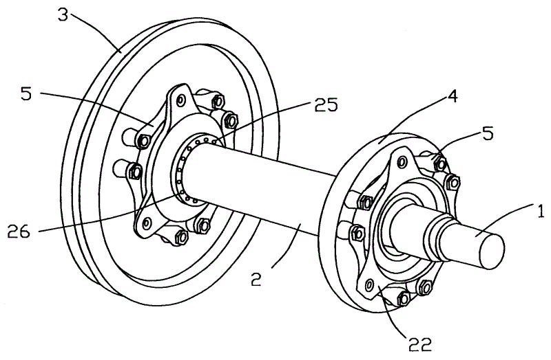
图1是本实用新型的叠片式六连杆轮对空心轴装置的结构示意图;Fig. 1 is the structural representation of the hollow shaft device of the stacked six-link wheel set of the utility model;
图2是本实用新型的叠片式六连杆轮对空心轴装置的剖视示意图;Fig. 2 is a schematic cross-sectional view of the hollow shaft device of the laminated six-link wheel set of the present invention;
图3A、图3B是本实用新型的叠片式六连杆轮对空心轴装置的叠片式连杆示意图,其图3A是主视示意图,图3B为立体示意图;Fig. 3A and Fig. 3B are schematic diagrams of the stacked connecting rods of the hollow shaft device of the stacked six-link wheel set of the present invention, and Fig. 3A is a schematic front view, and Fig. 3B is a schematic perspective view;
图4是本实用新型的叠片式六连杆轮对空心轴装置的叠片式连杆与传动盘的连接结构示意图;Fig. 4 is a schematic diagram of the connection structure between the laminated connecting rod and the transmission disc of the laminated six-link wheel set hollow shaft device of the present invention;
图5是本实用新型的叠片式六连杆轮对空心轴装置的叠片式连杆与车轮或驱动齿轮的连接结构示意图。5 is a schematic diagram of the connection structure between the laminated connecting rod and the wheel or driving gear of the hollow shaft device of the laminated six-link wheel set of the present invention.
具体实施方式 Detailed ways
为对本实用新型的目的、特征、技术效果有更加清楚的理解,现对照附图来说明本实用新型的叠片式六连杆轮对空心轴装置。In order to have a clearer understanding of the purpose, features, and technical effects of the utility model, the hollow shaft device of the laminated six-link wheel set of the utility model is now described with reference to the accompanying drawings.
如图1、2、3A、3B所示,本实用新型提出的叠片式六连杆轮对空心轴装置,具有套置在车轴1上的空心轴2,在所述车轴1的两端固定有车轮3,所述空心轴2的两端分别设有一传动盘21、22,其中一传动盘22与驱动齿轮4相连接,另一传动盘21与固定在所述车轴一端的车轮3相连接,其中,所述传动盘22与驱动齿轮4、传动盘21与车轮3之间分别通过六个连杆5相连接,所述连杆5为由多个金属薄片层叠构成的叠片式连杆,每一叠片式连杆5的一端(第一端)51与所述传动盘相连接,另一端(第二端)52与所述驱动齿轮4或车轮3相连接。所述各叠片式连杆5与驱动齿轮4的两侧、车轮3的两侧呈平行设置。As shown in Figures 1, 2, 3A, and 3B, the laminated six-link wheel set hollow shaft device proposed by the utility model has a
设置在所述空心轴2两端的传动盘21、22,与所述空心轴2可以为一体构成,也可以是分体式固定连接。在本实施例中,与驱动齿轮4相连接的传动盘22与所述空心轴2一体构成,与所述车轮3相连接的传动盘21通过螺栓25和传力销26与所述空心轴2固定为一体。The
当然所述两传动盘21、22也可以设置成均与空心轴为分体结构,通过螺栓和传力销与空心轴2固定为一体,以便于制造。所述传动盘21、22与空心轴2的结构并不限于此,该传动盘21、22与空心轴2也可为一体式结构,以提高其强度,减少连接部件。Of course, the two
所述传动盘21、22上均布设有多个通孔,带有锥形的衬套23贯穿所述通孔。如图4所示,所述衬套23与所述传动盘的通孔相配合的外周面为锥形,该衬套23的一端为固定端,设有大于所述通孔直径的止挡部231;另一端为连接端,延伸至所述通孔的外部,为等直径柱状体232;所述衬套23的连接端,即等直径柱状体232设有内螺纹,所述叠片式连杆5的一端套设在所述柱状体232上,一山字型第一压盖24盖合于所述衬套23的连接端,所述第一压盖24两外侧竖直部241顶抵于所述叠片式连杆5,第一压盖24中部的竖直部242与衬套23的连接端内螺纹相连接。A plurality of through holes are evenly distributed on the
如图5所示,所述车轮3或驱动齿轮4上均布固定有多个连杆销6,所述连杆销6的连接端61延伸至所述车轮3或驱动齿轮4的外部,所述连杆销6的连接端61设有内凹的嵌合孔63,所述叠片式连杆5的另一端套设在所述连杆销6的连接端61上;一山字型第二压盖62盖合于所述连杆销6的连接端61,所述第二压盖62两外侧竖直部621顶抵于所述叠片式连杆5,第二压盖62中部的竖直部622与所述连杆销6的连接端的嵌合孔63嵌合固定连接。As shown in Figure 5, a plurality of connecting rod pins 6 are uniformly fixed on the
如图1所示,在本实施例中,所述传动盘21、22上分别设有三个通孔,所述连杆5两个为一组,每组连杆的第一端51与所述传动盘相连接,第二端52分别与所述车轮3或驱动齿轮4相连接。当然,所述连杆5与车轮、驱动齿轮和传动盘的连接方式并不限于此,如也可以是在所述传动盘上设置六个通孔,每一连杆的第一端分别与所述传动盘相连接。As shown in Figure 1, in this embodiment, the
本实用新型的叠片式六连杆轮对空心轴装置的工作原理是:将两端设有传动盘21、22的所述空心轴2套置在车轴1上,连杆销6采用过盈配合分别镶嵌固定在车轮3上和驱动齿轮4的轮芯上,叠片式连杆5的第二端52套在连杆销6上,再加上止动垫后用压盖62压紧,为防止所述压盖62松动,可增加止动垫,并翻起止动垫边。设置于空心轴两端的传动盘21、22上分别镶嵌固定有带有锥形的衬套23,衬套23的连接端上设有与第一压盖24相配的内螺纹,叠片式连杆5的第一端51就套在衬套23的连接端上,再加上止动垫后用第一压盖24压紧,为防止所述压盖24松动,翻起止动垫边。这样依此类推,轮对的两侧各装有六个叠片式的连杆单元,连同轮对(车轮3和车轴1)、驱动齿轮4、空心轴2、传力销26、螺栓25、传动盘21、22等主要部件组成叠片式六连杆轮对空心轴装置。The working principle of the hollow shaft device of the stacked six-link wheel set of the utility model is: the
其传力过程为:驱动齿轮4转动→安装在驱动齿轮4上的连杆销6→与驱动齿轮4相连接的叠片式连杆5→镶嵌在传动盘22上的衬套23→传动盘22→空心轴2→传动盘21→镶嵌在传动盘21上的衬套23→与车轮3相连接的叠片式连杆5→安装在车轮3上的连杆销6→驱动车轮3。The force transmission process is: the driving gear 4 rotates → the connecting rod pin 6 installed on the driving gear 4 → the laminated
本实用新型采用多个金属薄片层叠构成的叠片式连杆5,通过金属片的变形来补偿相连接的两传动盘21、22平行平面之间的轴向位移和角度变化,本实用新型的叠片式连杆与传动盘21、22和车轮、驱动齿轮之间分别由衬套23、连杆销6和压盖相连接,较公知的橡胶关节式连接结构减小了六连杆的结构尺寸,降低了簧下重量,从而提高了机车的动力学性能,并克服了橡胶关节易于老化的缺陷。The utility model adopts a laminated connecting
唯上所述者,仅为本实用新型的具体实施例,不能以其限定本实用新型实施的范围,其等同组件的放大,缩小,置换,或依本实用新型专利保护范围所作的等同变化与修改,均仍然属于本实用新型权利要求书之涵盖范围。Only the above-mentioned ones are only specific embodiments of the present utility model, and cannot limit the scope of implementation of the present utility model with it. It is equivalent to the enlargement, reduction, replacement of components, or the equivalent changes made according to the protection scope of the utility model patent. Amendments still belong to the scope of coverage of the claims of the present invention.
Claims (7)
Priority Applications (1)
| Application Number | Priority Date | Filing Date | Title |
|---|---|---|---|
| CNU2007201493020U CN201061985Y (en) | 2007-05-25 | 2007-05-25 | Laminated six-link wheel-assembly hollow axle device |
Applications Claiming Priority (1)
| Application Number | Priority Date | Filing Date | Title |
|---|---|---|---|
| CNU2007201493020U CN201061985Y (en) | 2007-05-25 | 2007-05-25 | Laminated six-link wheel-assembly hollow axle device |
Publications (1)
| Publication Number | Publication Date |
|---|---|
| CN201061985Y true CN201061985Y (en) | 2008-05-21 |
Family
ID=39450356
Family Applications (1)
| Application Number | Title | Priority Date | Filing Date |
|---|---|---|---|
| CNU2007201493020U Expired - Fee Related CN201061985Y (en) | 2007-05-25 | 2007-05-25 | Laminated six-link wheel-assembly hollow axle device |
Country Status (1)
| Country | Link |
|---|---|
| CN (1) | CN201061985Y (en) |
Cited By (4)
| Publication number | Priority date | Publication date | Assignee | Title |
|---|---|---|---|---|
| CN111911545A (en) * | 2019-05-27 | 2020-11-10 | 中车大同电力机车有限公司 | Transmission mechanism and drive coupling |
| CN112109492A (en) * | 2019-06-20 | 2020-12-22 | 中车兰州机车有限公司 | Rail vehicle wheel mounting and positioning device |
| WO2021036831A1 (en) * | 2019-08-30 | 2021-03-04 | 北京海益同展信息科技有限公司 | Moving device and rail inspection robot |
| CN115366030A (en) * | 2022-09-22 | 2022-11-22 | 天津电力机车有限公司 | Assembly method and tool for axisymmetric parts of gear box structure driving device |
-
2007
- 2007-05-25 CN CNU2007201493020U patent/CN201061985Y/en not_active Expired - Fee Related
Cited By (6)
| Publication number | Priority date | Publication date | Assignee | Title |
|---|---|---|---|---|
| CN111911545A (en) * | 2019-05-27 | 2020-11-10 | 中车大同电力机车有限公司 | Transmission mechanism and drive coupling |
| WO2020238077A1 (en) * | 2019-05-27 | 2020-12-03 | 中车大同电力机车有限公司 | Transmission mechanism and driving shaft coupler |
| CN112109492A (en) * | 2019-06-20 | 2020-12-22 | 中车兰州机车有限公司 | Rail vehicle wheel mounting and positioning device |
| WO2021036831A1 (en) * | 2019-08-30 | 2021-03-04 | 北京海益同展信息科技有限公司 | Moving device and rail inspection robot |
| CN115366030A (en) * | 2022-09-22 | 2022-11-22 | 天津电力机车有限公司 | Assembly method and tool for axisymmetric parts of gear box structure driving device |
| CN115366030B (en) * | 2022-09-22 | 2025-07-08 | 天津电力机车有限公司 | Gear box structure driving device axisymmetric part assembling method and tooling |
Similar Documents
| Publication | Publication Date | Title |
|---|---|---|
| CN201833829U (en) | Novel half-shaft structural engineering machinery steering-driving front axle | |
| CN102529684B (en) | Wheel-side deceleration driving device of equal-length double wishbone suspension | |
| CN203920263U (en) | A kind of drive axle that is applicable to construction machinery and equipment | |
| CN201751219U (en) | Automobile front suspension lower sway arm assembly | |
| CN206797043U (en) | The multi-link lever suspension fork Direct wheel drives system of wheel hub motor direct-driving electric electrical automobile | |
| CN203157648U (en) | Balanced suspension system using cone-shaped rubber bearings | |
| CN206988318U (en) | A kind of universal joint for power transmission shaft | |
| CN211139450U (en) | Hydraulic steering drive front axle for wheel type engineering machinery and wheel type engineering machinery | |
| CN205022356U (en) | Vertical drive unit of electric fork -lift with connection pad | |
| CN211869078U (en) | Drive axle and sleeve flange thereof | |
| CN209925518U (en) | Gear ring support and hub bearing integrated structure | |
| CN201539512U (en) | A Universal Coupling | |
| CN103640436B (en) | Rear drive axle assembly | |
| CN201220577Y (en) | Medium-sized rear drive axle | |
| CN222522448U (en) | A wheel excavator electric drive axle assembly | |
| CN205631946U (en) | A wheel hub assembly for commercial transaxle | |
| CN203236972U (en) | Matching structure of automobile rim and automobile half axial flange | |
| CN202180711U (en) | 4.5 ton driving front axle | |
| CN105059113A (en) | Vehicle-bridge structure | |
| CN205706001U (en) | Semifloating axle shaft and driven cylindrical gear portal drive axle wheel limit structure integrally | |
| CN221803239U (en) | A new transmission shaft support frame | |
| CN217347361U (en) | Automobile driving axle housing | |
| CN218316086U (en) | Novel shaft type half shaft full-floating structure of tricycle axle | |
| CN203666389U (en) | Inspection robot and its walking mechanism | |
| CN224159449U (en) | Dual-shaft, dual-power electric drive structure for aircraft |
Legal Events
| Date | Code | Title | Description |
|---|---|---|---|
| C14 | Grant of patent or utility model | ||
| GR01 | Patent grant | ||
| C17 | Cessation of patent right | ||
| CF01 | Termination of patent right due to non-payment of annual fee |
Granted publication date: 20080521 Termination date: 20140525 |