CN201055736Y - Air separating and cleaning device - Google Patents
Air separating and cleaning device Download PDFInfo
- Publication number
- CN201055736Y CN201055736Y CNU200720147875XU CN200720147875U CN201055736Y CN 201055736 Y CN201055736 Y CN 201055736Y CN U200720147875X U CNU200720147875X U CN U200720147875XU CN 200720147875 U CN200720147875 U CN 200720147875U CN 201055736 Y CN201055736 Y CN 201055736Y
- Authority
- CN
- China
- Prior art keywords
- air
- cylinder
- filter
- separation
- partition
- Prior art date
- Legal status (The legal status is an assumption and is not a legal conclusion. Google has not performed a legal analysis and makes no representation as to the accuracy of the status listed.)
- Expired - Fee Related
Links
- 238000004140 cleaning Methods 0.000 title claims description 13
- 238000000926 separation method Methods 0.000 claims abstract description 36
- 238000005192 partition Methods 0.000 claims abstract description 20
- 239000000428 dust Substances 0.000 claims description 28
- 239000000463 material Substances 0.000 claims description 12
- 230000002093 peripheral effect Effects 0.000 claims description 2
- 230000000694 effects Effects 0.000 abstract description 8
- 239000012535 impurity Substances 0.000 abstract description 8
- XLYOFNOQVPJJNP-UHFFFAOYSA-N water Chemical compound O XLYOFNOQVPJJNP-UHFFFAOYSA-N 0.000 description 9
- 239000007789 gas Substances 0.000 description 7
- 238000001914 filtration Methods 0.000 description 6
- OKTJSMMVPCPJKN-UHFFFAOYSA-N Carbon Chemical compound [C] OKTJSMMVPCPJKN-UHFFFAOYSA-N 0.000 description 4
- 239000003921 oil Substances 0.000 description 3
- 239000004071 soot Substances 0.000 description 3
- 238000004332 deodorization Methods 0.000 description 2
- 150000002500 ions Chemical class 0.000 description 2
- 230000001954 sterilising effect Effects 0.000 description 2
- 238000004659 sterilization and disinfection Methods 0.000 description 2
- 239000002912 waste gas Substances 0.000 description 2
- 230000007613 environmental effect Effects 0.000 description 1
- 239000003517 fume Substances 0.000 description 1
- 210000002816 gill Anatomy 0.000 description 1
- 238000000034 method Methods 0.000 description 1
- 238000012986 modification Methods 0.000 description 1
- 230000004048 modification Effects 0.000 description 1
- 239000002245 particle Substances 0.000 description 1
- 239000000779 smoke Substances 0.000 description 1
Images



Classifications
-
- Y—GENERAL TAGGING OF NEW TECHNOLOGICAL DEVELOPMENTS; GENERAL TAGGING OF CROSS-SECTIONAL TECHNOLOGIES SPANNING OVER SEVERAL SECTIONS OF THE IPC; TECHNICAL SUBJECTS COVERED BY FORMER USPC CROSS-REFERENCE ART COLLECTIONS [XRACs] AND DIGESTS
- Y02—TECHNOLOGIES OR APPLICATIONS FOR MITIGATION OR ADAPTATION AGAINST CLIMATE CHANGE
- Y02A—TECHNOLOGIES FOR ADAPTATION TO CLIMATE CHANGE
- Y02A50/00—TECHNOLOGIES FOR ADAPTATION TO CLIMATE CHANGE in human health protection, e.g. against extreme weather
- Y02A50/20—Air quality improvement or preservation, e.g. vehicle emission control or emission reduction by using catalytic converters
- Y02A50/2351—Atmospheric particulate matter [PM], e.g. carbon smoke microparticles, smog, aerosol particles, dust
Landscapes
- Filtering Of Dispersed Particles In Gases (AREA)
Abstract
本实用新型是一种空气分离清净机装置,主要在一筒状机壳内装设有一抽风主机,所述的机壳在其上、下两端分别设有一进气口与一排气口而形成过滤通道,而可在所述的过滤通道间设有过滤设备者;其特征在:所述的机壳是包含有一上筒体与一下筒体,所述的上、下筒体之间有一隔板,所述的隔板中央有圆孔与设在下筒体内的抽风主机的吸气口相接,以及在所述的上、下筒体内分别装设有一前置分离构造与一空气滤网;据上述组合使用时,其能有效分离杂质以得到清新空气的功效。
The utility model is an air separation purifier device, which is mainly equipped with an exhaust main unit in a cylindrical casing, wherein the casing is respectively provided with an air inlet and an exhaust port at the upper and lower ends thereof to form a filter channel, and a filter device can be provided between the filter channels; the utility model is characterized in that: the casing comprises an upper cylinder and a lower cylinder, a partition is provided between the upper and lower cylinders, a circular hole is provided in the center of the partition to connect with the air inlet of the exhaust main unit provided in the lower cylinder, and a pre-separation structure and an air filter are respectively provided in the upper and lower cylinders; when used in the above combination, it can effectively separate impurities to obtain the effect of fresh air.
Description
技术领域technical field
本实用新型涉及空气清洁设备,特别是指一种空气分离清净机装置。The utility model relates to air cleaning equipment, in particular to an air separation and cleaning machine device.
背景技术Background technique
现在的社会对生活质量与环保意识的要求愈来愈高,甚至有些产业对废气的排放,以及室内空气的温度、湿度与落尘均有严格要求的情况下;故一部能确实有效分离与滤除空气中的杂质,而得到清净空气的空气分离清净机是有其必要的。Today's society has higher and higher requirements for quality of life and environmental protection awareness, and even some industries have strict requirements on exhaust gas emissions, as well as indoor air temperature, humidity and dust; therefore, one can really effectively separate and filter It is necessary to remove impurities in the air to obtain clean air.
本案实用新型设计人有鉴于上述人们对空气质量的要求愈来愈高的情况下;经过精心研究,并积个人从事所述的项产品的研究与设计多年的经验,终于研发设计出一种崭新的空气分离清净机装置。In view of the above-mentioned people’s higher and higher requirements for air quality, the designer of the utility model in this case finally developed and designed a brand-new The air separation cleaner device.
发明内容Contents of the invention
本实用新型主要目的在于:提供一种空气分离清净机装置,其可有效的滤除空气中所含的粉尘、灰烟、油烟或水气等杂质,且可延长抽风主机的使用后命的构造。The main purpose of the utility model is to provide an air separation and cleaning machine device, which can effectively filter out impurities such as dust, ash, oily smoke or water vapor contained in the air, and can prolong the life of the exhaust main engine. .
为达上述的目的,本实用新型空气分离清净机装置,主要在一筒状机壳内装设有一抽风主机,所述的机壳在其上、下两端分别设有一进气口与一排气口形成过滤通道,并在所述的过滤通道间设有一层以上的过滤设备者;其中,所述的机壳是包含有一上筒体与一下筒体迭置组成,所述的上筒体顶面中央具有一进气口,所述的下筒体底面设有排气口,以及在所述的上、下筒体之间设有一隔板,所述的隔板中央有圆孔;所述的抽风主机是装设在下筒体内的中央位置,包含一个固定在马达上的碟形壳体,与在碟形壳体内装设有一涡轮叶片,所述的涡轮叶片与马达的转轴连结而可旋转;所述的碟形壳体在其顶面具有一吸风口,与在其侧壁面沿其切线方向环设有数个向外的腮形出风口;所述的过滤设备包含设在上筒体内的前置分离构造与设在下筒体内的空气滤网。In order to achieve the above-mentioned purpose, the air separation cleaner device of the present utility model is mainly equipped with a main engine for exhausting air in a cylindrical casing, and the upper and lower ends of the casing are respectively provided with an air inlet and an exhaust. The mouth forms a filter channel, and more than one layer of filter equipment is arranged between the filter channels; wherein, the casing is composed of an upper cylinder and a lower cylinder, and the top of the upper cylinder is There is an air inlet in the center of the surface, the bottom surface of the lower cylinder is provided with an exhaust port, and a partition is provided between the upper and lower cylinders, and there is a round hole in the center of the partition; The exhaust air main engine is installed in the central position of the lower cylinder, including a disc-shaped housing fixed on the motor, and a turbine blade is installed in the disc-shaped housing, and the turbine blade is connected to the shaft of the motor so as to be rotatable ; The dish-shaped housing has an air suction port on its top surface, and several outward gill-shaped air outlets are arranged on its side wall along its tangential direction; The pre-separation structure and the air filter set in the lower cylinder.
与现有技术相比较,采用上述技术方案的本实用新型具有的优点在于:据上述组合使用时,所述的抽风主机启动旋转后,所述的上筒体内部形成负压,使废气由其顶面中央的进气口吸入,经前置分离构造将粉尘、烟灰或油、水等杂质与空气分离,其次,所述的初步经分离过滤后的空气才由抽风主机顶面的吸风口进入,再由其侧壁面的腮形出风口向外吹出,然后经设在下筒体的空气滤网进行第二次的过滤后,才由所述的下筒体底面的排气口排出,以能达到有效且较佳的空气过滤功效,并可延长抽风主机的使用寿命。Compared with the prior art, the utility model adopting the above-mentioned technical solution has the advantage that: according to the above-mentioned combined use, after the exhaust main engine starts to rotate, a negative pressure is formed inside the upper cylinder, so that the waste gas is discharged from it. The air inlet in the center of the top surface is inhaled, and the dust, soot, oil, water and other impurities are separated from the air through the pre-separation structure. Secondly, the air that has been initially separated and filtered enters through the suction port on the top surface of the exhaust main unit. , and then blow out from the gill-shaped air outlet on the side wall, and then pass through the air filter set on the lower cylinder for the second time to filter, and then be discharged from the exhaust port on the bottom of the lower cylinder, so as to To achieve effective and better air filtration effect, and prolong the service life of the exhaust air host.
附图说明Description of drawings
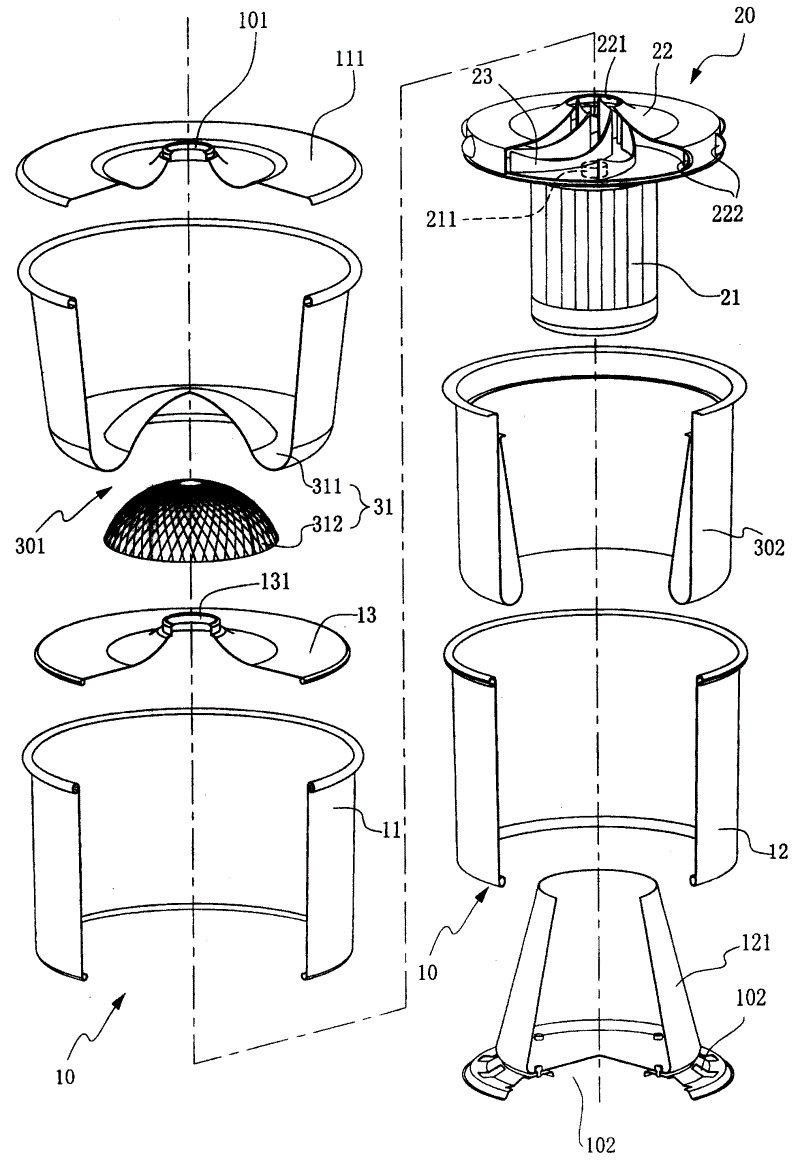
图1为本实用新型的一实施例的立体分解图;Fig. 1 is the three-dimensional exploded view of an embodiment of the utility model;
图2为图1的组合剖面图;Fig. 2 is the combined sectional view of Fig. 1;
图3为本实用新型另一实施例的组合剖面图;Fig. 3 is a combined sectional view of another embodiment of the utility model;
图4为本实用新型再一实施例的组合剖面图;Fig. 4 is a combined sectional view of yet another embodiment of the utility model;
图5为本实用新型又一实施例的组合剖面图。Fig. 5 is a combined sectional view of another embodiment of the present invention.
附图标记说明:10-机壳;20-抽风主机;40-底盖;50-导管;11-上筒体;12-下筒体;13-隔板;21-马达;22-碟形壳体;23-涡轮叶片;31-集尘组;32-空气清净组;33-油气分离组;41-导管接头;101-进气口;102-排气口;103-过滤通道;111-顶盖;121-罩体;131-圆孔;211-转轴;221-吸风口;222-腮形出风口;301-前置分离构造;302-空气滤网;311、321-集尘袋;312-网架;322、332-中筒;323、333-内管;324、334-空气滤材;331-环形集油网;3221、3322-盖板;3222、3323-腮形进风口;3321-腮形出风口。Explanation of reference signs: 10-casing; 20-exhaust main engine; 40-bottom cover; 50-duct; 11-upper cylinder; 12-lower cylinder; 13-baffle; 21-motor; 22-disc shell body; 23-turbine blade; 31-dust collection group; 32-air cleaning group; 33-oil-gas separation group; 41-conduit joint; 101-air inlet; 102-exhaust port; Cover; 121-cover body; 131-circular hole; 211-rotating shaft; 221-suction port; 222-gill-shaped air outlet; 301-front separation structure; 302-air filter; - grid frame; 322, 332 - middle tube; 323, 333 - inner tube; 324, 334 - air filter material; 331 - ring oil collecting net; 3221, 3322 - cover plate; 3222, 3323 - gill-shaped air inlet; 3321 -Gill-shaped air outlet.
具体实施方式Detailed ways
为使贵审查委员对本实用新型的构造、装置及其特征有更进一步的认识与了解,兹举其几个可行实施例并配合图式详细说明如下:In order to make your examining committee members have a further understanding and understanding of the structure, device and features of the present utility model, hereby cite several possible embodiments thereof and describe them in detail with the accompanying drawings as follows:
请参阅图1至图4所示,本实用新型空气分离清净机装置,主要在一机壳10内装设有一抽风主机20,所述的机壳10在其上、下两端分别设有一进气口101与一排气口102使在所述的壳体内形成一过滤通道103,并在所述的过滤通道103间设有一层以上的过滤设备者;其中,Please refer to Fig. 1 to shown in Fig. 4, the utility model air separation purifier device, mainly is equipped with an
所述的机壳10是包含有一上筒体11与一下筒体12迭置组成,所述的上筒体11顶面中央具有一进气口101,所述的下筒体12底面设有排气口102(所述的排气孔可有数个环设在底板周边或/与一个设在底面中央),以及在所述的上、下筒体11、12之间设有一隔板13,所述的隔板13中央有圆孔131,通过采用所述的圆孔131以连通上、下筒体11、12间的过滤通道103;The
所述的抽风主机20是装设在下筒体12内的中央位置,包含一个固定在马达21上的碟形壳体22,与在碟形壳体22内装设有一涡轮叶片23,所述的涡轮叶片23与马达21的转轴211连结而可旋转;所述的碟形壳体22在其顶面具有一吸风口221,与在其侧壁面沿其切线方向环设有数个向外的腮形出风口222;The air exhaust
所述的过滤设备包含设在上筒体11内的前置分离构造301与设在下筒体12内的空气滤网302。The filtering device includes a
如上述,本案实施时,所述的隔板13是装设固定在上筒体11的底部,其也可固定在下筒体12的顶端,或直接由抽风主机20的蝶形壳体22的顶板衍生制成。又,在抽风主机20的马达21外部得以一罩体121包覆,而使其与过滤通道103隔离,以便于控制过滤通道103的密闭性与防止马达积尘。As mentioned above, during the implementation of this case, the
据上述组合使用时,所述的抽风主机20启动旋转后,所述的上筒体11内部形成负压,使废气(待处理的空气)由其顶面中央的进气口101吸入,经前置分离构造301将粉尘、烟灰或油、水等杂质与空气分离,其次,所述的初步经分离过滤后的空气才由抽风主机20顶面的吸风口221进入,再由其侧壁面的腮形出风口222向外吹出,然后经设在下筒体12的空气滤网302进行第二次的过滤后,才由所述的下筒体12底面的排气口102排出,以达到分离杂质与清净空气的功效,并可通过采用多重的分离与过滤效果而延长装置的寿命。According to the combination of the above, after the
如上述的装置,其中所述的上筒体11内的前置分离构造301,可为一集尘组31或空气清净组32或油气分离组33,以因应用来分离与过滤粉尘、灰烟或油烟、水气等不同的杂质。As in the above-mentioned device, the
所述的集尘组31(如图1与图2所示),其包含一集尘袋311、一网架312组成,所述的集尘袋311是呈圆袋状,以其袋口套设在所述的上筒体11上端口缘及其顶盖111之间;所述的网架312是呈半球形,覆盖在所述的上、下筒体间的隔板13的圆孔131上方。组合使用时,所述的集尘袋311底部因网架312的支撑而与隔板13的圆孔131间形成有一空隙,避免所述的集尘袋311贴附在上筒体11的内壁与隔板13的上以可增加其透气面积,所以当废气由进气口101进入集尘袋311后,其能均匀的通过集尘袋311再由圆孔131进入下筒体12,而可发挥较大的滤尘效果。The dust collection group 31 (as shown in Fig. 1 and Fig. 2 ) comprises a
所述的空气清净组32(如图3所示),其包含一环形集尘袋321、一中筒322、一内管323,与设在中筒322与内管323间的数层空气滤材324所组成,所述的中筒322是固定在上、下筒体间的隔板13上,在其顶面设有一盖板3221,并在其底端的壁面上沿其切线方向环设有数个向内的腮形进风口3222;所述的内管323是套设在上述隔板13中央的圆孔131上,且其顶端与中筒322的盖板3221底面具有一段空间;所述的环形集尘袋321的外口缘是套设在所述的上筒体11上端口缘与顶盖111之间,其内口缘是套设在中筒322的顶缘及其盖板3221之间。组合使用时,其因中筒322与内管323的设置,使在所述的上筒体11内的过滤通道103形成由外而内曲折的型态,延长所述的信道的长度而可增设更多的空气滤材324,其行进路线如图中的箭头指标所示;又,其中除了有一环形集尘袋321的外,再配合在中筒322与内管323的通道间所设置的多层空气滤材324(如:活性碳或电极网...)的作用,使其具有除尘、除臭或杀菌或增加负离子的清净空气功效。The air cleaning group 32 (as shown in Figure 3 ) comprises an annular
所述的油气分离组33(如图4所示),其包含一环形集油(水)网331、一中筒332、一内管333,与设在中筒332与内管333间的数层空气滤材334所组成,所述的环形集油网331是设在所述的上筒体11内壁面与中筒332的外壁面之间;所述的中筒332是固定在上、下筒体间的隔板13上,在所述的中筒332顶端的壁面上沿其切线方向环设有数个向外的腮形出风口3321,在所述的腮形出风口3321下缘设有一盖板3322,并在所述的中筒332的底端壁面上沿其切线方向环设有数个向内的腮形进风口3323;所述的内管333是套设在上述隔板13中央的圆孔131上,且其顶端与中筒的盖板3322底面具有一段空间。Described oil-gas separation group 33 (as shown in Figure 4), it comprises an annular oil collection (water)
如上述组合使用时,所述的环形集油网331实施时可由多片垂直的网板以辐射状排列,或以多片环状网板上下多层排列,或以一网板以螺旋状绕设,以使废气中所含的油或水附着在所述的环形集油网331上,达到分离与收集空气中所含的油份或水份的目的;其次,因中筒332与内管333的设置,使在所述的上筒体11内的过滤通道103形成由外而内曲折的型态,延长所述的过滤信道的长度而可增设更多的空气滤材334,其行进路线如图中的箭头指标所示,故所述的一构造在经环形集油网331作初步的分离工作后,可再经设在中筒332与内管333的通道间所设置的空气滤材334(如;滤油网或活性碳、电极网...等),而进行第二次的分离油、水工作,或/与进行除尘、除臭或杀菌或增加负离子的清净空气工作,以达到本实用新型所预期的目的。When used in combination as described above, the annular
据上所述的各式前置分离构造301可在废气进入所述的抽风主机20的前,即可依不同的滤材或构造而过滤掉较大颗粒的粉尘或油质或水份等,进而达到将空气中的杂质分离过滤外,更可使所述的抽风主机20及其后端的空气滤网302可减少污染,以延长其使用寿命。According to the above-mentioned various
再请参阅图1至图4所示,所述的下筒体12内的空气滤网302是呈环状袋体,所述的空气滤网302的外口缘是套设在所述的下筒体12上端口缘上,其内口缘是套设在抽风主机20的碟形壳体22底板上,且所述的空气滤网302的网目较前置分离构造301中的滤网或滤材的网目(空隙)小;据而,其可滤除较细微的粉尘,达到较佳的空气清净效果。Please refer to Figures 1 to 4 again, the
另请参阅图5所示,其中也可在一空气分离清净机装置的下筒体12底面设一底盖40,所述的底盖40包覆在下筒体12底面的排气口102,并在所述的底盖40的一侧突出下筒体12周壁外,且向上设有一导管接头41;据而,当以一导管50连接在此一底盖40的导管接头41的后,所述的导管50的另一端可连接至另一空气分离清净机装置上端的进气口101,即可达到串连使用的多重过滤功效,以能进一步的提升所述的一产品的实用性与经济价值。See also shown in Fig. 5, wherein also can establish a
以上说明对本实用新型而言只是说明性的,而非限制性的,本领域普通技术人员理解,在不脱离权利要求所限定的精神和范围的情况下,可作出许多修改、变化或等效,但都将落入本实用新型的权利要求可限定的范围之内。The above description is only illustrative, rather than restrictive, of the present utility model. Those of ordinary skill in the art understand that many modifications, changes or equivalents can be made without departing from the spirit and scope defined in the claims. But all will fall within the limitable scope of the claims of the present utility model.
Claims (6)
Priority Applications (1)
| Application Number | Priority Date | Filing Date | Title |
|---|---|---|---|
| CNU200720147875XU CN201055736Y (en) | 2007-06-01 | 2007-06-01 | Air separating and cleaning device |
Applications Claiming Priority (1)
| Application Number | Priority Date | Filing Date | Title |
|---|---|---|---|
| CNU200720147875XU CN201055736Y (en) | 2007-06-01 | 2007-06-01 | Air separating and cleaning device |
Publications (1)
| Publication Number | Publication Date |
|---|---|
| CN201055736Y true CN201055736Y (en) | 2008-05-07 |
Family
ID=39424582
Family Applications (1)
| Application Number | Title | Priority Date | Filing Date |
|---|---|---|---|
| CNU200720147875XU Expired - Fee Related CN201055736Y (en) | 2007-06-01 | 2007-06-01 | Air separating and cleaning device |
Country Status (1)
| Country | Link |
|---|---|
| CN (1) | CN201055736Y (en) |
Cited By (6)
| Publication number | Priority date | Publication date | Assignee | Title |
|---|---|---|---|---|
| CN104562424A (en) * | 2015-02-03 | 2015-04-29 | 海宁汉德袜业有限公司 | Dust removal device in hosiery machine |
| CN104593941A (en) * | 2015-02-03 | 2015-05-06 | 海宁汉德袜业有限公司 | Dust Collecting Mechanism in Automatic Hosiery Knitting Machine |
| CN104740946A (en) * | 2015-01-05 | 2015-07-01 | 中山市兆美电子电器有限公司 | Air filter |
| CN105641990A (en) * | 2016-03-28 | 2016-06-08 | 张浩楠 | Sewage sand-filtering equipment |
| CN110613979A (en) * | 2018-06-19 | 2019-12-27 | 盐城市恒星石油化学有限公司 | A sulfur trioxide output purification process for white mineral oil production |
| CN110873375A (en) * | 2018-08-31 | 2020-03-10 | 广东美的白色家电技术创新中心有限公司 | Interception device, purification device and air purifier for air purification |
-
2007
- 2007-06-01 CN CNU200720147875XU patent/CN201055736Y/en not_active Expired - Fee Related
Cited By (11)
| Publication number | Priority date | Publication date | Assignee | Title |
|---|---|---|---|---|
| CN104740946A (en) * | 2015-01-05 | 2015-07-01 | 中山市兆美电子电器有限公司 | Air filter |
| CN104562424A (en) * | 2015-02-03 | 2015-04-29 | 海宁汉德袜业有限公司 | Dust removal device in hosiery machine |
| CN104593941A (en) * | 2015-02-03 | 2015-05-06 | 海宁汉德袜业有限公司 | Dust Collecting Mechanism in Automatic Hosiery Knitting Machine |
| CN104562424B (en) * | 2015-02-03 | 2016-08-24 | 海宁汉德袜业有限公司 | Dust removal device in hosiery machine |
| CN104593941B (en) * | 2015-02-03 | 2017-01-18 | 海宁汉德袜业有限公司 | Dust Collecting Mechanism in Automatic Hosiery Knitting Machine |
| CN105641990A (en) * | 2016-03-28 | 2016-06-08 | 张浩楠 | Sewage sand-filtering equipment |
| CN105641990B (en) * | 2016-03-28 | 2018-01-23 | 张浩楠 | A kind of sewage filter sand equipment |
| CN110613979A (en) * | 2018-06-19 | 2019-12-27 | 盐城市恒星石油化学有限公司 | A sulfur trioxide output purification process for white mineral oil production |
| CN110613979B (en) * | 2018-06-19 | 2023-08-04 | 盐城市恒星石油化学有限公司 | Sulfur trioxide output purification process for white mineral oil production |
| CN110873375A (en) * | 2018-08-31 | 2020-03-10 | 广东美的白色家电技术创新中心有限公司 | Interception device, purification device and air purifier for air purification |
| US11439934B2 (en) | 2018-08-31 | 2022-09-13 | Guangdong Midea White Home Appliance Technology Innovation Center Co., Ltd. | Capture device for purifying air, purification device and air purifier |
Similar Documents
| Publication | Publication Date | Title |
|---|---|---|
| US8012230B2 (en) | Structure of an impurities collecting bucket for an air separator and purifier | |
| US8012226B2 (en) | Air separator and purifier device | |
| CN106923748A (en) | Hand-held cyclone dust collection and corresponding dust pelletizing system | |
| CN106121877A (en) | A kind of air filter and electromotor | |
| KR100527358B1 (en) | Air cleaner having cyclone | |
| JP4390738B2 (en) | Air cleaner | |
| CN211676713U (en) | a dust removal device | |
| CN206001608U (en) | A kind of kitchen air purifying device | |
| CN102527182A (en) | Welding smoke purification device | |
| CN116530872A (en) | Dust-gas separation assembly, filtering device and cleaning equipment | |
| CN213955551U (en) | Dust removing device | |
| CN112892869A (en) | Electrostatic dust removal equipment with internal circulation type self-cleaning system | |
| CN207734833U (en) | A kind of Environmental-protecting dust-removing equipment | |
| CN105903276A (en) | Dust falling device | |
| CN111594489A (en) | Cyclone type air inlet particle combined filter for magnetic suspension air blower | |
| CN215892681U (en) | Multifunctional self-circulation air purifier | |
| CN206409326U (en) | Noise abatement air cleaner | |
| CN216986842U (en) | Dust removal filter cylinder, dust remover and dust removal system | |
| CN212415620U (en) | Dust collecting box of self-moving cleaning device and self-moving cleaning device with dust collecting box | |
| CN214440018U (en) | An internal circulation self-cleaning system for electrostatic dust removal equipment | |
| CN102293610B (en) | Cyclone separating device | |
| CN109331589B (en) | Absorption formula falls haze dust collecting system | |
| CN205128211U (en) | Multilayer multi -chamber sectional type dust remover | |
| CN105457401A (en) | Filtering component and air purifier | |
| CN218565717U (en) | Novel filter element structure of air purifier |
Legal Events
| Date | Code | Title | Description |
|---|---|---|---|
| C14 | Grant of patent or utility model | ||
| GR01 | Patent grant | ||
| CF01 | Termination of patent right due to non-payment of annual fee |
Granted publication date: 20080507 Termination date: 20160601 |