CN201055533Y - Sterilizing cabinet - Google Patents
Sterilizing cabinet Download PDFInfo
- Publication number
- CN201055533Y CN201055533Y CNU200720111200XU CN200720111200U CN201055533Y CN 201055533 Y CN201055533 Y CN 201055533Y CN U200720111200X U CNU200720111200X U CN U200720111200XU CN 200720111200 U CN200720111200 U CN 200720111200U CN 201055533 Y CN201055533 Y CN 201055533Y
- Authority
- CN
- China
- Prior art keywords
- cabinet
- steel wire
- cabinet body
- slide bar
- chute
- Prior art date
- Legal status (The legal status is an assumption and is not a legal conclusion. Google has not performed a legal analysis and makes no representation as to the accuracy of the status listed.)
- Expired - Fee Related
Links
Images

Abstract
The utility model discloses a disinfection cabinet, which comprises a cabinet body and a bottom plate. The cabinet body is provided with a cabinet door and the bottom plate is provided with a fan, an ultraviolet lamp tube, an inner guts and a plurality of pulling bars which are arranged in the inner guts. A lifting device is arranged between the cabinet body and the bottom plate. The lifting device comprises a motor, a steel wire and two pulleys. The motor is fixedly arranged on the top of the inner wall of the cabinet body, the two pulleys are respectively fixedly arranged the two sided of the inner wall of the cabinet body, the middle piece of the steel wire is connected with the motor. The two ends of the steel wire are penetrated and winded on the pulley and is connected with the inner guts. A guide device which comprises a chute and a slide bar is arranged in the lifting device. The utility model has the advantages that users can operate and control the lifting device through a function button, so the inner guts can move up and down inside or outside the cabinet body. The goods in the disinfection cabinet can be fetched and placed neatly and expediently. On the other hand, the mutual cooperation of the chute and the slide bar results in that the inner guts can reposefully move up and down inside and outside the cabinet body. In addition, the utility model is of simple structure, convenient processing and manufacturing, low cost and space saving.
Description
Technical field
This utility model relates to a kind of disinfecting device, especially relates to a kind of disinfection cabinet.
Background technology
Along with growth in the living standard, people more and more pay attention to the health problem of health, for guaranteeing the health of tableware, ensure the health of human body, and now a lot of families all have been equipped with Sterilization and Disinfection Equipment such as dishware disinfection cabinet.Existing disinfection cabinet kind is a lot of on the market, and as plug-type, suspension type and vertical opening door, these disinfection cabinets mainly are made up of cabinet, cabinet door, decontaminating apparatus and control device.Consider space saving problem, at present, a lot of families can use underslung dishware disinfection cabinet for saving kitchen space.But this underslung dishware disinfection cabinet can only adopt and be fixedly mounted on the wall, in case can not arbitrarily adjust the height of disinfection cabinet after the successful installation as required, if install too highly, what the kinsfolk was short reaches, and it is just relatively more dangerous to pick and place article from disinfection cabinet; If installed lowly, not only influenced spatial effective utilization, but also can hinder one's work, at this moment, caused great puzzlement to the user if wanting to readjust the position of disinfection cabinet must unload disinfection cabinet then and reinstall.
Summary of the invention
Technical problem to be solved in the utility model provides a kind of simple in structure, the disinfection cabinet that accessing article is convenient and practical.
This utility model solves the problems of the technologies described above the technical scheme that is adopted: a kind of disinfection cabinet, comprise cabinet and base plate, described cabinet is provided with the cabinet door, described base plate is provided with blower fan, quartz burner, inner bag and is arranged on the interior some baskets that draw of inner bag, is provided with lowering or hoisting gear between described cabinet and the described base plate.
Described lowering or hoisting gear comprises motor, steel wire and two pulleys, described motor is fixedly installed in described cabinet inwall top, described pulley is fixedly installed in both sides, described cabinet inwall top respectively, described steel wire stage casing is connected with described motor, described steel wire two ends are around described pulley, are connected with described inner bag.
Be provided with guider in the described lowering or hoisting gear, described guider comprises chute and slide bar, described chute is arranged at described cabinet inwall both sides, described slide bar is arranged at described inner bag both sides, described chute and described slide bar cooperatively interact, and described steel wire two ends are passed described chute and are connected with described slide bar.
Compared with prior art, advantage of the present utility model is to be provided with lowering or hoisting gear between cabinet and the base plate, the user can move up and down inner bag easily by function button operation control lowering or hoisting gear automatically inside and outside cabinet, can pick and place the article in the disinfection cabinet flexibly and easily; On the other hand, cooperatively interacting of the chute of guider and slide bar makes inner bag external enwergy in cabinet move up and down reposefully, and in addition, this utility model is simple in structure, convenient processing and manufacture, and cost is low, and has saved the space.
Description of drawings
Fig. 1 is in the intravital structural representation of cabinet for inner bag of the present utility model;
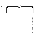
Fig. 2 is descend structural representation outside cabinet of inner bag of the present utility model;
Fig. 3 looks sketch map for the left side of the disinfection cabinet of Fig. 2.
The specific embodiment
Embodiment describes in further detail this utility model below in conjunction with accompanying drawing.
As Fig. 1, Fig. 2 and shown in Figure 3, a kind of disinfection cabinet comprises cabinet 1 and base plate 2, and cabinet 1 is provided with cabinet door 3, base plate 2 is provided with blower fan 4, quartz burner 5, inner bag 6 and is arranged on some baskets 7 that draw in the inner bag 6, and is provided with lowering or hoisting gear between cabinet 1 and the base plate 2.
Lowering or hoisting gear comprises motor 8, steel wire 9 and two pulleys 10, and motor 8 is fixedly installed in cabinet 1 inwall top, exportable predetermined power; Pulley 10 is fixedly installed in both sides, cabinet 1 inwall top respectively, and steel wire 9 stage casings are connected with motor 8, and steel wire 9 two ends are around pulley 10, are connected with inner bag 6.
Be provided with guider in lowering or hoisting gear, guider comprises chute 11 and slide bar 12, and chute 11 is arranged at cabinet 1 inwall both sides, and slide bar 12 is arranged at inner bag 6 both sides, and chute 11 cooperatively interacts with slide bar 12, and steel wire 9 two ends are passed chute 11 and are connected with slide bar 12.
In the present embodiment, cabinet door 3 is provided with function button 13 and display screen 14, realizes every function operations by function button 13, can observe duty of the present utility model by display screen 14.
Operation principle of the present utility model is as follows: when disinfection cabinet did not use, as shown in Figure 1, inner bag 6 was in the cabinet 1, and base plate 2 constitutes seal with cabinet 1 driving fit.The disinfection cabinet energized is used, when picking and placeing article, the user can be by the button with inner bag 6 decline functions in the function button on the lower cabinet door 3 13, at this moment, motor 8 starts, export pre-determined power, steel wire 9 is unclamped synchronously by two pulleys 10, the slide bar 12 that is connected with steel wire 9 at the uniform velocity descends along chute 11, in the time of outside inner bag 6 places cabinet 1 fully, as shown in Figure 2, motor 8 stops outputting power, and at this moment the user can pick and place article from drawing blue 7 easily; After article pick and place and finish, the user can be by the button with inner bag 6 rising functions in the function button on the lower cabinet door 3 13, at this moment, motor 8 is activated again, and outputting power makes steel wire 9 synchronously around rising, the slide bar 12 that is connected with steel wire 9 at the uniform velocity rises along chute 11, in inner bag 6 places cabinet 1 fully, during the complete driving fit of base plate 2 and cabinet 1, as shown in Figure 1, motor 8 stops outputting power, and at this moment the user can carry out disinfection to article.
Claims (3)
1. disinfection cabinet, comprise cabinet and base plate, described cabinet is provided with the cabinet door, and described base plate is provided with blower fan, quartz burner, inner bag and is arranged on the interior some baskets that draw of inner bag, it is characterized in that being provided with lowering or hoisting gear between described cabinet and the described base plate.
2. a kind of disinfection cabinet as claimed in claim 1, it is characterized in that described lowering or hoisting gear comprises motor, steel wire and two pulleys, described motor is fixedly installed in described cabinet inwall top, described pulley is fixedly installed in both sides, described cabinet inwall top respectively, described steel wire stage casing is connected with described motor, described steel wire two ends are around described pulley, are connected with described inner bag.
3. a kind of disinfection cabinet as claimed in claim 2, it is characterized in that being provided with guider in the described lowering or hoisting gear, described guider comprises chute and slide bar, described chute is arranged at described cabinet inwall both sides, described slide bar is arranged at described inner bag both sides, described chute and described slide bar cooperatively interact, and described steel wire two ends are passed described chute and are connected with described slide bar.
Priority Applications (1)
| Application Number | Priority Date | Filing Date | Title |
|---|---|---|---|
| CNU200720111200XU CN201055533Y (en) | 2007-06-25 | 2007-06-25 | Sterilizing cabinet |
Applications Claiming Priority (1)
| Application Number | Priority Date | Filing Date | Title |
|---|---|---|---|
| CNU200720111200XU CN201055533Y (en) | 2007-06-25 | 2007-06-25 | Sterilizing cabinet |
Publications (1)
| Publication Number | Publication Date |
|---|---|
| CN201055533Y true CN201055533Y (en) | 2008-05-07 |
Family
ID=39424376
Family Applications (1)
| Application Number | Title | Priority Date | Filing Date |
|---|---|---|---|
| CNU200720111200XU Expired - Fee Related CN201055533Y (en) | 2007-06-25 | 2007-06-25 | Sterilizing cabinet |
Country Status (1)
| Country | Link |
|---|---|
| CN (1) | CN201055533Y (en) |
Cited By (6)
| Publication number | Priority date | Publication date | Assignee | Title |
|---|---|---|---|---|
| CN102511702A (en) * | 2011-12-30 | 2012-06-27 | 苏州韩博厨房电器科技有限公司 | Novel food disinfection cabinet |
| CN101590249B (en) * | 2009-06-24 | 2012-08-22 | 马信芳 | Safety type lifting disinfecting Cabinet and lifting protection method thereof |
| CN103658098A (en) * | 2013-11-21 | 2014-03-26 | 南车青岛四方机车车辆股份有限公司 | Bearing, shaft box and accessory washing device and method |
| CN106620799A (en) * | 2016-11-03 | 2017-05-10 | 成都聚智工业设计有限公司 | Lifting type dynamic air-purification sterilizing vehicle |
| CN107412824A (en) * | 2017-07-10 | 2017-12-01 | 杭州老板电器股份有限公司 | A kind of disinfection cabinet |
| CN109602927A (en) * | 2018-12-25 | 2019-04-12 | 杭州丽博家居有限公司 | A kind of disinfection cabinet and its method for customizing based on UVC ultraviolet disinfection |
-
2007
- 2007-06-25 CN CNU200720111200XU patent/CN201055533Y/en not_active Expired - Fee Related
Cited By (8)
| Publication number | Priority date | Publication date | Assignee | Title |
|---|---|---|---|---|
| CN101590249B (en) * | 2009-06-24 | 2012-08-22 | 马信芳 | Safety type lifting disinfecting Cabinet and lifting protection method thereof |
| CN102511702A (en) * | 2011-12-30 | 2012-06-27 | 苏州韩博厨房电器科技有限公司 | Novel food disinfection cabinet |
| CN103658098A (en) * | 2013-11-21 | 2014-03-26 | 南车青岛四方机车车辆股份有限公司 | Bearing, shaft box and accessory washing device and method |
| CN103658098B (en) * | 2013-11-21 | 2016-08-17 | 中车青岛四方机车车辆股份有限公司 | Bearing, axle box and accessory cleaning device and method |
| CN106620799A (en) * | 2016-11-03 | 2017-05-10 | 成都聚智工业设计有限公司 | Lifting type dynamic air-purification sterilizing vehicle |
| CN107412824A (en) * | 2017-07-10 | 2017-12-01 | 杭州老板电器股份有限公司 | A kind of disinfection cabinet |
| CN109602927A (en) * | 2018-12-25 | 2019-04-12 | 杭州丽博家居有限公司 | A kind of disinfection cabinet and its method for customizing based on UVC ultraviolet disinfection |
| CN109602927B (en) * | 2018-12-25 | 2024-03-08 | 杭州丽博家居有限公司 | Sterilizing cabinet based on UVC ultraviolet sterilization and customizing method thereof |
Similar Documents
| Publication | Publication Date | Title |
|---|---|---|
| CN201055533Y (en) | Sterilizing cabinet | |
| CN101653615B (en) | Sterilizing cabinet with electrical drawing and lifting device | |
| CN201481857U (en) | Automatic pulling and pushing lifting device of drawers of sterilization cabinet or kitchen cabinet | |
| CN201055528Y (en) | Sterilizing cabinet | |
| CN209815425U (en) | Elevator button sterilizing device | |
| CN101686754B (en) | Liftable suspended cupboard | |
| JP2009011757A (en) | Elevating/lowering type wall cabinet for kitchen | |
| CN201260800Y (en) | Up-down disinfection cabinet | |
| CN103054348A (en) | Method and device enabling shoes to be hanged on ceiling for hidden storage | |
| CN204842427U (en) | Go into formula fume chamber | |
| CN202858308U (en) | Front-pull-down lifting type self-opening movable wall cupboard | |
| CN201481826U (en) | Embedded disinfection cabinet with lifting pull baskets | |
| CN204747038U (en) | Console mode fume chamber | |
| CN202288490U (en) | Foot-operated sterilized towel rack for operating room | |
| CN206652013U (en) | Sterilize pass-through box | |
| CN111991162B (en) | Medical care dressing change cart | |
| CN213911461U (en) | Medical protective equipment disinfection cabinet for epidemic prevention and control | |
| CN212117505U (en) | Multifunctional wardrobe | |
| CN211186344U (en) | Cleaning wardrobe with height adjusting function | |
| CN210842193U (en) | Lifting type disinfection cabinet and cupboard | |
| CN216393490U (en) | Hanging cabinet with electric lifting seasoning basket | |
| CN201481828U (en) | Embedded disinfection cabinet with pulling and lifting function | |
| CN207023756U (en) | A kind of down-sliding type cabinet drawer | |
| CN203989111U (en) | Sterilizing machine | |
| CN220442201U (en) | Intelligent integrated wardrobe |
Legal Events
| Date | Code | Title | Description |
|---|---|---|---|
| C14 | Grant of patent or utility model | ||
| GR01 | Patent grant | ||
| CF01 | Termination of patent right due to non-payment of annual fee |
Granted publication date: 20080507 Termination date: 20140625 |
|
| EXPY | Termination of patent right or utility model |