CN201031764Y - Non-contact metal seal structure of turbine main shaft - Google Patents
Non-contact metal seal structure of turbine main shaft Download PDFInfo
- Publication number
- CN201031764Y CN201031764Y CNU2007200956400U CN200720095640U CN201031764Y CN 201031764 Y CN201031764 Y CN 201031764Y CN U2007200956400 U CNU2007200956400 U CN U2007200956400U CN 200720095640 U CN200720095640 U CN 200720095640U CN 201031764 Y CN201031764 Y CN 201031764Y
- Authority
- CN
- China
- Prior art keywords
- sealing
- main shaft
- seal
- seat body
- axle sleeve
- Prior art date
- Legal status (The legal status is an assumption and is not a legal conclusion. Google has not performed a legal analysis and makes no representation as to the accuracy of the status listed.)
- Expired - Fee Related
Links
- 239000002184 metal Substances 0.000 title abstract description 6
- 238000007789 sealing Methods 0.000 claims abstract description 64
- 238000012423 maintenance Methods 0.000 claims description 15
- 229910001220 stainless steel Inorganic materials 0.000 claims description 3
- 239000010935 stainless steel Substances 0.000 claims description 3
- 239000000463 material Substances 0.000 claims description 2
- 239000007769 metal material Substances 0.000 claims description 2
- NJPPVKZQTLUDBO-UHFFFAOYSA-N novaluron Chemical compound C1=C(Cl)C(OC(F)(F)C(OC(F)(F)F)F)=CC=C1NC(=O)NC(=O)C1=C(F)C=CC=C1F NJPPVKZQTLUDBO-UHFFFAOYSA-N 0.000 claims 11
- 239000002699 waste material Substances 0.000 claims 3
- 238000007689 inspection Methods 0.000 abstract description 14
- XLYOFNOQVPJJNP-UHFFFAOYSA-N water Substances O XLYOFNOQVPJJNP-UHFFFAOYSA-N 0.000 abstract description 14
- 238000004519 manufacturing process Methods 0.000 abstract description 3
- 238000001816 cooling Methods 0.000 abstract description 2
- 238000011161 development Methods 0.000 abstract description 2
- 238000005461 lubrication Methods 0.000 abstract description 2
- 230000000694 effects Effects 0.000 description 2
- 238000005516 engineering process Methods 0.000 description 2
- 238000012986 modification Methods 0.000 description 2
- 230000004048 modification Effects 0.000 description 2
- 230000032683 aging Effects 0.000 description 1
- 238000013461 design Methods 0.000 description 1
- 230000018109 developmental process Effects 0.000 description 1
- 238000000034 method Methods 0.000 description 1
- 230000008092 positive effect Effects 0.000 description 1
- 239000004576 sand Substances 0.000 description 1
- 239000007787 solid Substances 0.000 description 1
Images

Classifications
-
- Y—GENERAL TAGGING OF NEW TECHNOLOGICAL DEVELOPMENTS; GENERAL TAGGING OF CROSS-SECTIONAL TECHNOLOGIES SPANNING OVER SEVERAL SECTIONS OF THE IPC; TECHNICAL SUBJECTS COVERED BY FORMER USPC CROSS-REFERENCE ART COLLECTIONS [XRACs] AND DIGESTS
- Y02—TECHNOLOGIES OR APPLICATIONS FOR MITIGATION OR ADAPTATION AGAINST CLIMATE CHANGE
- Y02E—REDUCTION OF GREENHOUSE GAS [GHG] EMISSIONS, RELATED TO ENERGY GENERATION, TRANSMISSION OR DISTRIBUTION
- Y02E10/00—Energy generation through renewable energy sources
- Y02E10/20—Hydro energy
Landscapes
- Sealing Devices (AREA)
Abstract
本实用新型涉及一种水轮机主轴无接触式金属密封结构,包括:主轴、轴套以及密封座体,主轴上固装有轴套,密封座体内圈上紧固有轴瓦并制有数个凹槽,密封座体下端连接有检修密封座体,该密封检修座体靠近轴套一侧嵌装有检修密封,密封座体轴瓦内侧面、检修密封座体内侧面与轴套之间设有间隙,密封座体最下或上层的凹槽上连接有密封排水管。其优点在于:该轴封的密封座体与轴套部分不接触,减少了不必要的磨损,延长了主轴密封的使用寿命;解决了水压密封因水压不稳而带来的密封性能不稳定的问题;在正常水轮机运行时不需要冷却或润滑,可降低生产成本,具有较好的市场发展前景。
The utility model relates to a non-contact metal sealing structure for a main shaft of a hydraulic turbine, comprising: a main shaft, a shaft sleeve and a sealing seat body, a shaft sleeve is fixedly installed on the main shaft, and a bearing bush is fastened on the inner ring of the sealing seat and several grooves are formed. The lower end of the seal seat body is connected with an inspection seal body, and the side of the seal inspection seat body close to the shaft sleeve is embedded with an inspection seal. A sealed drainage pipe is connected to the groove on the bottom or upper layer of the body. Its advantages are: the seal seat of the shaft seal is not in contact with the shaft sleeve, which reduces unnecessary wear and prolongs the service life of the main shaft seal; solves the problem of poor sealing performance of the hydraulic seal caused by unstable water pressure. Stability problem; no cooling or lubrication is required during normal turbine operation, which can reduce production costs and has a good market development prospect.
Description
技术领域technical field
本实用新型属于水轮机制造技术领域,特别是涉及一种结构简单、密封性能可靠且使用寿命长的水轮机主轴无接触式金属密封结构。The utility model belongs to the technical field of water turbine manufacturing, in particular to a non-contact metal sealing structure for a main shaft of a water turbine with simple structure, reliable sealing performance and long service life.
背景技术Background technique
水轮机主轴密封的主要作用是封阻水轮机转动部分与固定部分之间的间隙漏水。而水轮机主轴密封效果的好坏直接影响到机组的稳定运行。目前公知的水轮机比较常用的主轴密封形式为水压式密封,它是通过水压将密封块顶起,并与抗磨板摩擦,从而阻止水流通过,达到密封的目的。水压式密封的缺陷是:由于水压不稳会带来密封性能不稳定的问题;在水中有时会存在沙粒或固体物质,这样容易使轴套与密封座体(密封块和抗磨板)之间产生磨损加大,降低了密封件的使用寿命;此外由于密封块本身的材质所限,存在着老化问题,因此也会影响主轴密封的可靠性。The main function of the main shaft seal of the turbine is to block water leakage in the gap between the rotating part and the fixed part of the turbine. The quality of the sealing effect of the main shaft of the turbine directly affects the stable operation of the unit. At present, the commonly used main shaft seal form of known water turbines is a hydraulic seal, which uses water pressure to lift the seal block and rub against the wear plate, thereby preventing the passage of water and achieving the purpose of sealing. The disadvantages of hydraulic seals are: unstable sealing performance due to unstable water pressure; sand or solid matter sometimes exists in the water, which is easy to make the shaft sleeve and sealing seat (seal block and wear plate) ) between increased wear and tear, reducing the service life of the seal; in addition, due to the limited material of the seal block itself, there is an aging problem, which will also affect the reliability of the spindle seal.
发明内容Contents of the invention
本实用新型为解决公知技术中存在的技术问题而提供一种结构简单、密封性能可靠且使用寿命长的水轮机主轴无接触式金属密封结构。The utility model provides a non-contact metal sealing structure for a main shaft of a hydraulic turbine with simple structure, reliable sealing performance and long service life in order to solve the technical problems existing in the known technology.
本实用新型为解决公知技术中存在的技术问题所采取的技术方案是:The technical scheme that the utility model takes for solving the technical problem existing in the known technology is:
水轮机主轴无接触式金属密封结构,包括:主轴、轴套以及密封座体,其特征在于:主轴上固装有金属材料制的轴套,在密封座体内圈上紧固有轴瓦并制有数个凹槽,密封座体下端通过螺柱连接有检修密封座体,该密封检修座体靠近轴套一侧嵌装有检修密封,所述密封座体轴瓦内侧面、检修密封座体内侧面与轴套之间设有间隙,在密封座体的凹槽上连接有密封排水管。The non-contact metal seal structure of the main shaft of the water turbine, including: the main shaft, the shaft sleeve and the sealing seat body, is characterized in that: the shaft sleeve made of metal material is fixed on the main shaft, the bearing bush is fastened on the inner ring of the sealing seat and several Groove, the lower end of the seal seat body is connected with an inspection seal body through studs, the seal inspection seat body is embedded with an inspection seal on the side close to the shaft sleeve, the inner side of the bearing bush of the seal seat body, the inner side surface of the inspection seal seat and the shaft sleeve There is a gap between them, and a sealing drainage pipe is connected to the groove of the sealing seat body.
本实用新型还可以采用如下技术措施:The utility model can also adopt the following technical measures:
所述密封座体内圈至少制有三个凹槽。The inner ring of the sealing seat is formed with at least three grooves.
密封座体最上层的凹槽上连接有密封排水管,亦可在密封座体最下层的凹槽上连接有密封排水管。A sealing drainage pipe is connected to the groove on the uppermost layer of the sealing seat body, and a sealing drainage pipe may also be connected to the groove on the lowermost layer of the sealing seat body.
所述密封座体轴瓦内侧面与轴套之间的间隙为0.6-0.8mm。The gap between the inner surface of the bearing bush of the sealing seat body and the shaft sleeve is 0.6-0.8mm.
所述检修密封座体内侧面与轴套之间的间隙为1.8-2.0mm。The gap between the inner side of the maintenance seal seat and the shaft sleeve is 1.8-2.0mm.
所述密封座体轴瓦为燕尾状结构。The bearing shell of the sealing seat has a dovetail structure.
所述轴套为不锈钢材料制的轴套。The shaft sleeve is a shaft sleeve made of stainless steel.
本实用新型具有的优点和积极效果是:由于本实用新型将主轴轴套与密封座体、检修密封座体之间设有间隙,使该轴封的密封座体、检修密封座体与轴套部分不接触,减少了不必要的磨损,延长了主轴密封的使用寿命;无需密封清洁水,并解决了水压密封因水压不稳而带来的密封性能不稳定的问题;本密封结构在正常水轮机运行时不需要冷却或润滑,可降低生产成本;此外本实用新型设计结构简单合理、密封性能可靠,具有较好的社会效益和经济效益,并具市场发展前景。The advantages and positive effects of the utility model are: because the utility model provides a gap between the main shaft sleeve and the sealing seat body and the maintenance sealing seat body, the sealing seat body of the shaft seal, the maintenance sealing body and the shaft sleeve The parts are not in contact, which reduces unnecessary wear and prolongs the service life of the main shaft seal; it does not need to seal clean water, and solves the problem of unstable sealing performance of the hydraulic seal caused by unstable water pressure; the sealing structure is in the No cooling or lubrication is required during normal water turbine operation, which can reduce production costs; in addition, the utility model has a simple and reasonable design structure, reliable sealing performance, good social and economic benefits, and has a market development prospect.
附图说明Description of drawings
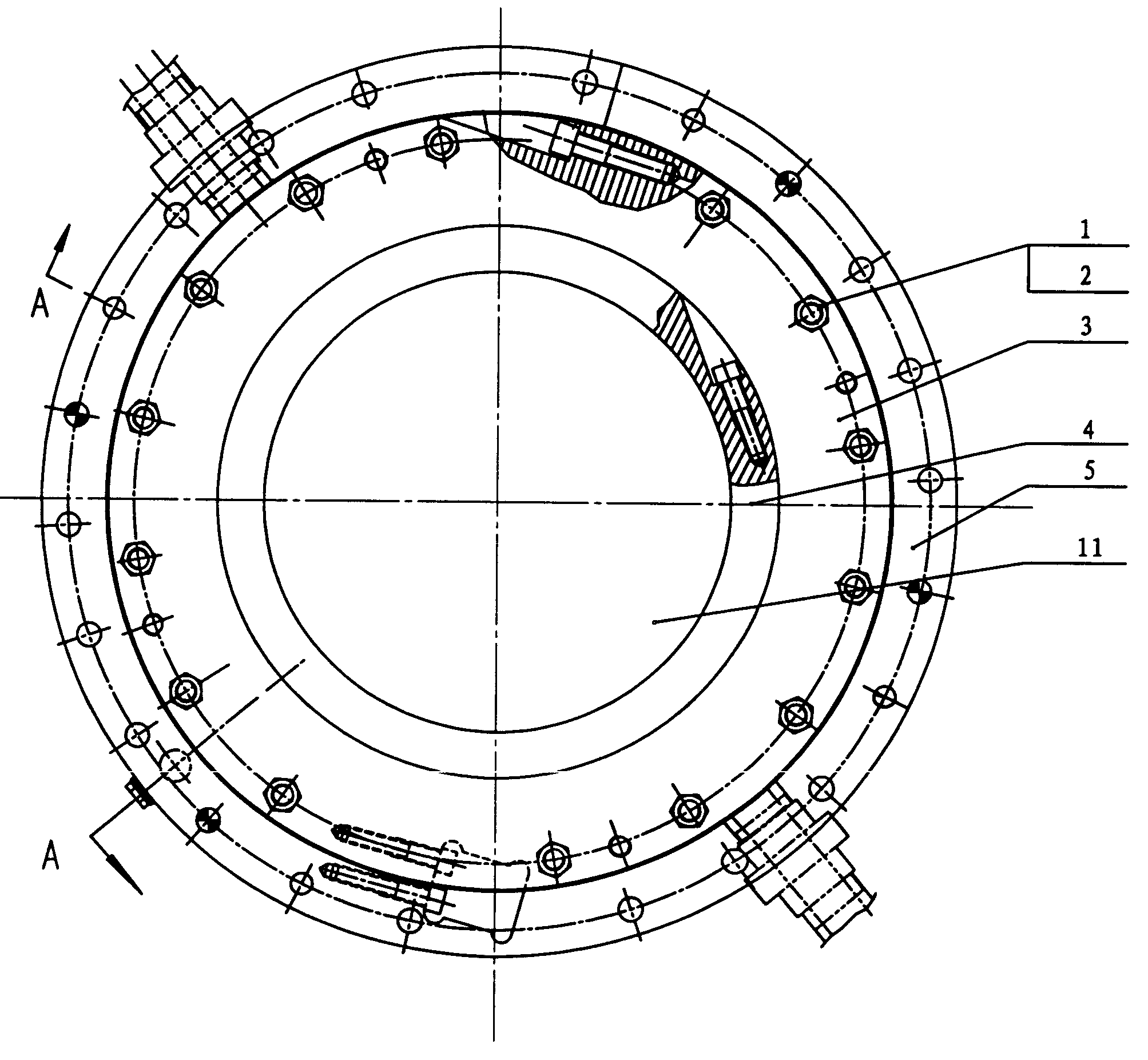
图1是本实用新型的结构示意图;Fig. 1 is a structural representation of the utility model;
图2是图1的A-A剖视图。Fig. 2 is a sectional view along A-A of Fig. 1 .
图中:1、螺柱;2、螺母;3、密封座体;3-1、凹槽;4、轴套;5、检修密封座体;6、密封条;7、检修密封;8、螺塞;9、垫圈;10、轴瓦;11、主轴;12、密封排水管;13、间隙。In the figure: 1. Stud; 2. Nut; 3. Seal body; 3-1. Groove; 4. Shaft sleeve; 5. Inspection seal body; 6. Sealing strip; Plug; 9. Gasket; 10. Bearing bush; 11. Main shaft; 12. Seal drain pipe; 13. Gap.
具体实施方式Detailed ways
为能进一步了解本实用新型的发明内容、特点及功效,兹例举以下实施例,并配合附图详细说明如下:In order to further understand the invention content, characteristics and effects of the present utility model, the following examples are given, and detailed descriptions are as follows in conjunction with the accompanying drawings:
请参阅图1和图2,水轮机主轴无接触式金属密封结构,包括:主轴11、轴套4以及密封座体3,主轴11上固装有不锈钢材料制的轴套4,在密封座体3内圈上紧固有呈燕尾状的轴瓦10并至少制有三个凹槽3-1,在密封座体最下或最上层的凹槽3-1上连接有两根对称分布的密封排水管12。密封座体下端通过螺柱1和螺母2紧固连接有检修密封座体5,检修密封座体固定在顶盖上,密封座体3与检修密封座体5的连接处还设有由橡胶材质制作的密封条6。该密封检修座体5靠近轴套4一侧嵌装有检修密封7,该检修密封7采用空气围带式密封,空气压力为0.5-0.8MPa。当水轮机组停机时,检修密封7充气膨胀与主轴紧密贴合,达到检修密封的目的。所述密封座体轴瓦10内侧面、检修密封座体5内侧面与轴套4之间设有间隙13,以形成转动部分轴套4与静止部分密封座体轴瓦10和检修密封座体5不接触。所述密封座体轴瓦内侧面与轴套之间的间隙为0.6-0.8mm,所述检修密封座体内侧面与轴套之间的间隙为1.8-2.0mm。所述检修密封座体5的外圆径向上还安装有用于调节检修密封7的螺塞8和垫圈9。Please refer to Figure 1 and Figure 2, the non-contact metal seal structure of the main shaft of the hydraulic turbine, including: the
以上所述,仅是本实用新型的较佳实施例而已,并非对本实用新型作任何形式上的限制,凡是依据本实用新型的技术实质对以上实施例所作的任何简单修改、等同变化与修饰,均属于本实用新型技术方案的范围内。The above is only a preferred embodiment of the utility model, and does not limit the utility model in any form. Any simple modification, equivalent change and modification made to the above embodiments according to the technical essence of the utility model, All belong to the scope of the technical solution of the utility model.
Claims (7)
Priority Applications (1)
| Application Number | Priority Date | Filing Date | Title |
|---|---|---|---|
| CNU2007200956400U CN201031764Y (en) | 2007-03-30 | 2007-03-30 | Non-contact metal seal structure of turbine main shaft |
Applications Claiming Priority (1)
| Application Number | Priority Date | Filing Date | Title |
|---|---|---|---|
| CNU2007200956400U CN201031764Y (en) | 2007-03-30 | 2007-03-30 | Non-contact metal seal structure of turbine main shaft |
Publications (1)
| Publication Number | Publication Date |
|---|---|
| CN201031764Y true CN201031764Y (en) | 2008-03-05 |
Family
ID=39163656
Family Applications (1)
| Application Number | Title | Priority Date | Filing Date |
|---|---|---|---|
| CNU2007200956400U Expired - Fee Related CN201031764Y (en) | 2007-03-30 | 2007-03-30 | Non-contact metal seal structure of turbine main shaft |
Country Status (1)
| Country | Link |
|---|---|
| CN (1) | CN201031764Y (en) |
Cited By (3)
| Publication number | Priority date | Publication date | Assignee | Title |
|---|---|---|---|---|
| CN101749165B (en) * | 2008-12-08 | 2012-03-07 | 国网新源控股有限公司回龙分公司 | Guide shoe clearance adjusting method for high rotary speed water turbine unit |
| CN102518806A (en) * | 2011-12-27 | 2012-06-27 | 重庆水轮机厂有限责任公司 | Spindle sealing device of axial flow hydraulic turbine |
| CN114876700A (en) * | 2022-06-13 | 2022-08-09 | 大唐雅安电力开发有限公司 | Water turbine maintenance sealing method and device based on air sealing |
-
2007
- 2007-03-30 CN CNU2007200956400U patent/CN201031764Y/en not_active Expired - Fee Related
Cited By (4)
| Publication number | Priority date | Publication date | Assignee | Title |
|---|---|---|---|---|
| CN101749165B (en) * | 2008-12-08 | 2012-03-07 | 国网新源控股有限公司回龙分公司 | Guide shoe clearance adjusting method for high rotary speed water turbine unit |
| CN102518806A (en) * | 2011-12-27 | 2012-06-27 | 重庆水轮机厂有限责任公司 | Spindle sealing device of axial flow hydraulic turbine |
| CN114876700A (en) * | 2022-06-13 | 2022-08-09 | 大唐雅安电力开发有限公司 | Water turbine maintenance sealing method and device based on air sealing |
| CN114876700B (en) * | 2022-06-13 | 2024-02-13 | 大唐雅安电力开发有限公司 | Water turbine maintenance sealing method based on air sealing |
Similar Documents
| Publication | Publication Date | Title |
|---|---|---|
| CN201621288U (en) | Two-seal surface stop valve with throttle teeth | |
| CN102927312A (en) | High-pressure top-mounted eccentric adjusting ball valve | |
| CN201516918U (en) | Anti-sand type controllable pitch propeller | |
| CN201401518Y (en) | Wear-resistant and sulfur-resistant double-sealed flat gate valve | |
| CN205639656U (en) | Blowdown trap | |
| CN206637030U (en) | A kind of flat cover sealing structure of high-pressure bottle | |
| CN217328512U (en) | Improved shaft end seal structure and its wear ring | |
| CN201858474U (en) | Novel rotary compensator structure | |
| CN201162057Y (en) | Pressure roller for electroplating unit | |
| CN111173667A (en) | Top cover water intake and pressure regulating device for mixed-flow unit with filtering function | |
| CN206159048U (en) | Centrifugation shurry pump | |
| CN104315147B (en) | Power type contactless main shaft sealing device | |
| CN204784719U (en) | A line contact L shape main shaft work sealing device for bearing seal | |
| CN205315713U (en) | Rotary kiln hood's high -efficient sealing device | |
| CN201599129U (en) | Pump Turbine Guide Vane Shaft Sealing Device | |
| CN202451825U (en) | Spindle seal self-compensating type structure | |
| CN202914369U (en) | Improved sealing structure of centrifugal pumps | |
| CN207437263U (en) | A kind of radial direction self-compensation type sealing | |
| CN221824461U (en) | A sealing device for axial flow pump turbine | |
| CN201372882Y (en) | New Type Hydraulic Turbine Main Shaft Sealing Assembly of "Non-contact Sealing Plus Rotary Pump Device" | |
| CN201126015Y (en) | Fluid kinetic pressure type seal machine for kettle | |
| CN106640669A (en) | Centrifugal slurry pump | |
| CN203500099U (en) | Low-pressure rotary shaft sealing device | |
| CN222717435U (en) | Novel sealing device on pull rod of medium-speed coal mill | |
| CN205401461U (en) | Shaft pivot bearing unloads die mould sealing washer |
Legal Events
| Date | Code | Title | Description |
|---|---|---|---|
| C14 | Grant of patent or utility model | ||
| GR01 | Patent grant | ||
| C17 | Cessation of patent right | ||
| CF01 | Termination of patent right due to non-payment of annual fee |
Granted publication date: 20080305 Termination date: 20120330 |