CN201024388Y - Hybrid bent frame for urban viaduct construction - Google Patents

Hybrid bent frame for urban viaduct construction Download PDF

Info

Publication number
CN201024388Y
CN201024388Y CNU2007200690375U CN200720069037U CN201024388Y CN 201024388 Y CN201024388 Y CN 201024388Y CN U2007200690375 U CNU2007200690375 U CN U2007200690375U CN 200720069037 U CN200720069037 U CN 200720069037U CN 201024388 Y CN201024388 Y CN 201024388Y
Authority
CN
China
Prior art keywords
steel pipe
steel
hybrid
construction
bent frame
Prior art date
Legal status (The legal status is an assumption and is not a legal conclusion. Google has not performed a legal analysis and makes no representation as to the accuracy of the status listed.)
Expired - Fee Related
Application number
CNU2007200690375U
Other languages
Chinese (zh)
Inventor
李申杰
张铭
罗玲丽
Current Assignee (The listed assignees may be inaccurate. Google has not performed a legal analysis and makes no representation or warranty as to the accuracy of the list.)
Shanghai City No4 Building Co Ltd
Original Assignee
Shanghai City No4 Building Co Ltd
Priority date (The priority date is an assumption and is not a legal conclusion. Google has not performed a legal analysis and makes no representation as to the accuracy of the date listed.)
Filing date
Publication date
Application filed by Shanghai City No4 Building Co Ltd filed Critical Shanghai City No4 Building Co Ltd
Priority to CNU2007200690375U priority Critical patent/CN201024388Y/en
Application granted granted Critical
Publication of CN201024388Y publication Critical patent/CN201024388Y/en
Anticipated expiration legal-status Critical
Expired - Fee Related legal-status Critical Current

Links

Classifications

    • Y—GENERAL TAGGING OF NEW TECHNOLOGICAL DEVELOPMENTS; GENERAL TAGGING OF CROSS-SECTIONAL TECHNOLOGIES SPANNING OVER SEVERAL SECTIONS OF THE IPC; TECHNICAL SUBJECTS COVERED BY FORMER USPC CROSS-REFERENCE ART COLLECTIONS [XRACs] AND DIGESTS
    • Y02—TECHNOLOGIES OR APPLICATIONS FOR MITIGATION OR ADAPTATION AGAINST CLIMATE CHANGE
    • Y02A—TECHNOLOGIES FOR ADAPTATION TO CLIMATE CHANGE
    • Y02A30/00—Adapting or protecting infrastructure or their operation
    • Y02A30/60—Planning or developing urban green infrastructure

Landscapes

  • Bridges Or Land Bridges (AREA)

Abstract

本实用新型涉及一种城市高架桥施工用混合式排架,包括一组间隔排列的钢管立柱,钢管立柱的底部固定在混凝土基础上,顶部上面固定连接有横梁,其特点是:相邻钢管立柱之间纵横向垂直平面内均用剪刀撑固定连接,中间用槽钢水平连接形成整体刚性框架。本实用新型由于采用混合支架,相对于传统的钢管满堂支架每立方空间米的含钢量大降低,从而使排架的稳定性得到了大大提高,又节省了工程造价;同时又能适用于现浇箱梁桥面高、箱体大、施工作业面受多层立体交通限制、施工周围环境复杂条件下的施工要求。

Figure 200720069037

The utility model relates to a hybrid bent frame for urban viaduct construction, which comprises a group of steel pipe columns arranged at intervals. The bottom of the steel pipe columns is fixed on the concrete foundation, and a beam is fixedly connected to the top. The vertical, horizontal, and vertical planes are fixed and connected with scissors braces, and the middle is horizontally connected with channel steel to form an overall rigid frame. Because the utility model adopts the mixed bracket, the steel content per cubic meter of the traditional steel pipe full-room bracket is greatly reduced, so that the stability of the bent bracket is greatly improved, and the engineering cost is saved; at the same time, it can be applied to the existing The pouring box girder has high bridge deck, large box body, the construction work surface is restricted by multi-layer three-dimensional traffic, and the construction surrounding environment is complex.

Figure 200720069037

Description

The hybrid framed bent of overhead road of city bridge construction
Technical field
The utility model relates to the framed bent that uses in a kind of overhead road of city building operations, especially a kind of hybrid framed bent of overhead road of city bridge construction that is used for surpassing height more than 30 meters.
Background technology
At present, in the overhead road of city building operations, cast-in-situ box girder adopts high framed bent method or bridge fabrication machine to realize usually.
One of cast-in-situ box girder method is to adopt traditional fastener steel tube solid matter framed bent, since cast-in-place beam from heavy load greatly, highly high, the total length of the fastener steel tube framed bent system vertical rod that 30m is above and the rod member compressive strain that the vertical rod banjo fixing butt jointing causes are bigger, and globality is affected.
Two of cast-in-situ box girder method is to adopt the bridge fabrication machine of municipal engineering to construct.But big for the case beam from heavy load, the wide and disunity of width, the column spacing is irregular, and the non-type viaduct of span then difficulty of construction is very big, the construction costs height.
Therefore for the cast-in-situ box girder bridge floor liftoff very high, casing is big from heavy load, width is wide, span is not of uniform size, the viaduct of layer stereo traffic restriction under the construction operation face, construction surrounding environment complexity, as above marine loop wire is crossed over the rack form that the cast-in-situ box girder construction of overpass bridge place, rainbow plum road just can't be adopted traditional full hall steel pipe, also can't use the construction of bridge fabrication machine bridge machine.
Summary of the invention
The utility model is for solving cast-in-situ box girder bridge floor height, casing is big, the construction operation face is subjected to layer stereo traffic restriction, construction surrounding environment complex conditions lower support framed bent technical problem, and the hybrid framed bent of a kind of overhead road of city bridge construction that provides.
For solving the problems of the technologies described above, the technical solution adopted in the utility model is as follows:
The hybrid framed bent of a kind of overhead road of city bridge construction, comprise one group of spaced large diameter steel pipe column, be characterized in: the bottom of ¢ 580 steel pipe posts is fixed on the concrete foundation, in vertical plane, all use the angle steel bridging fixedly connected between the adjacent steel tube column in length and breadth, every 12m high with No. 16 channel-section steel levels in length and breadth to being connected to form the integral rigidity framework.No. 56 i iron of laying are as the girder of steel platform above the steel pipe post top, lay No. 36 i iron on No. 56 i iron as the platform secondary beam, re-lay No. 12 i iron brace summer as the steel pipe support vertical rod, steel structure support is set up full hall bowl fastening type or fastener type steel pipe support again with top.Framed bent height on No. 12 i iron can by its down the height of steel platform control.
Steel pipe post top and bottom surface are equipped with flange, and flange is provided with several bolts hole; Upper and lower being connected and fixed by its flange and with bolt of steel pipe post connects; Bridging is welded by angle steel; The diameter of steel pipe post is 580mm, and wall thickness is 12mm, and length is 6m.
The utility model promptly adopts the bigger steel pipe of diameter to set up the rack form of platform in conjunction with full hall fastener steel tube owing to adopt combined support.Set up a steel platform with ¢ 580 steel pipes and shaped steel, on the steel platform, set up ¢ 48 steel pipe framed bents again.Scaffolding height control steel pipe framed bent scaffolding height by the steel platform.This structure work efficiency height is saved steel, framed bent resistance to overturning number, and safe mass easily guarantees.Steel content with respect to traditional every cubic space rice of steel pipe full framing reduces greatly, thereby makes the stability of framed bent obtain improving greatly, has saved construction costs again; Can be applicable to again that simultaneously cast-in-situ box girder bridge floor height, casing are big, the construction operation face is subjected to the construction requirement under layer stereo traffic restriction, the construction surrounding environment complex conditions.
Description of drawings
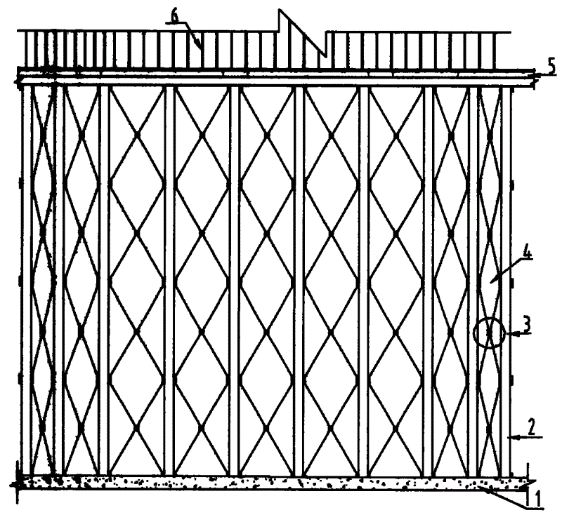
Fig. 1 is a structural representation of the present utility model.
The specific embodiment
Below in conjunction with accompanying drawing and embodiment the utility model is further described.Should be understood that these embodiment only to be used to the utility model is described and be not used in the restriction scope of the present utility model.Should be understood that in addition those skilled in the art can make various changes or modifications the utility model after the content of having read the utility model instruction, these equivalent form of values fall within the application's appended claims institute restricted portion equally.
As shown in Figure 1, the hybrid framed bent of overhead road of city bridge construction of the present utility model comprises one group of spaced steel pipe post 2, and the bottom of steel pipe post 2 is fixed on concrete 1 basis, is fixedly connected with crossbeam 5 above the top.
The diameter of steel pipe post 2 is 580mm, and wall thickness is 12mm, and length is 6m.Carry out spelling with steel pipe at length direction according to the height needs, at the certain height place, the horizontal connection platform is set, it is 48mm steel pipe framed bent 6 systems that steel structure support adopts diameter with top.
The steel pipe post 2 vertical flange that utilize the steel pipe upper and lower end to be provided with that connect, each flange is provided with several bolts hole, connects by bolt.
In vertical plane, be fixedly welded with bridging 3 between the steel pipe post 2 in length and breadth, thereby form an integral rigidity framework.Bridging 3 adopts angle steel 100X100X10mm.Steel pipe end face at contact platform place is set up a junction plate, and the horizontal connection platform adopts channel-section steel 4 conducts in length and breadth to the contact rod member, and channel-section steel 4 adopts electric welding to connect with the steel plate of setting up that is connected.In whole plane, the horizontal connection bridging is set.
Claims (4)

1.一种城市高架桥施工用混合式排架,包括一组间隔排列的钢管立柱(2),钢管立柱(2)的底部固定在混凝土(1)基础上,顶部上面固定连接有横梁(5),其特点是:相邻钢管立柱(2)之间纵横向垂直平面内均用剪刀撑(3)固定连接,中间用槽钢(4)水平连接形成整体刚性框架。1. A hybrid bent frame for urban viaduct construction, comprising a group of steel pipe columns (2) arranged at intervals, the bottom of the steel pipe columns (2) is fixed on the concrete (1) foundation, and a crossbeam (5) is fixedly connected to the top , which is characterized in that: the adjacent steel pipe columns (2) are fixedly connected by scissors braces (3) in the vertical, horizontal and vertical planes, and the middle is horizontally connected by channel steel (4) to form an integral rigid frame. 2.根据权利要求1所述的城市高架桥施工用混合式排架,其特征在于,所述钢管立柱(2)顶部和底面均设有法兰盘,法兰盘上设有若干个螺栓孔;钢管立柱(2)上、下连接固定通过其法兰盘并用螺栓连接。2. The hybrid bent frame for urban viaduct construction according to claim 1, characterized in that, the top and bottom surfaces of the steel pipe column (2) are provided with flanges, and the flanges are provided with several bolt holes; The steel pipe column (2) is connected and fixed up and down through its flange and connected with bolts. 3.根据权利要求1所述的城市高架桥施工用混合式排架,其特征在于,所述剪刀撑(3)由角钢焊接而成。3. The hybrid bent frame for urban viaduct construction according to claim 1, characterized in that the scissor brace (3) is welded by angle steel. 4.根据权利要求1或2所述的城市高架桥施工用混合式排架,其特征在于,所述钢管立柱(2)的直径为580mm,壁厚为12mm,长度为6m。4. The hybrid bent frame for urban viaduct construction according to claim 1 or 2, characterized in that the steel pipe column (2) has a diameter of 580mm, a wall thickness of 12mm, and a length of 6m.
CNU2007200690375U 2007-04-18 2007-04-18 Hybrid bent frame for urban viaduct construction Expired - Fee Related CN201024388Y (en)

Priority Applications (1)

Application Number Priority Date Filing Date Title
CNU2007200690375U CN201024388Y (en) 2007-04-18 2007-04-18 Hybrid bent frame for urban viaduct construction

Applications Claiming Priority (1)

Application Number Priority Date Filing Date Title
CNU2007200690375U CN201024388Y (en) 2007-04-18 2007-04-18 Hybrid bent frame for urban viaduct construction

Publications (1)

Publication Number Publication Date
CN201024388Y true CN201024388Y (en) 2008-02-20

Family

ID=39098242

Family Applications (1)

Application Number Title Priority Date Filing Date
CNU2007200690375U Expired - Fee Related CN201024388Y (en) 2007-04-18 2007-04-18 Hybrid bent frame for urban viaduct construction

Country Status (1)

Country Link
CN (1) CN201024388Y (en)

Cited By (4)

* Cited by examiner, † Cited by third party
Publication number Priority date Publication date Assignee Title
CN101974884A (en) * 2010-10-22 2011-02-16 山东省路桥集团有限公司 Tower-type triangular bracket system
CN103334381A (en) * 2013-06-25 2013-10-02 宁波市政工程建设集团股份有限公司 Full-bracket track-bogie bearing and moving device and construction method for installing steel box girders
CN108827683A (en) * 2018-07-20 2018-11-16 中国水利水电第七工程局有限公司 A kind of bridge bracket reverse drawing precompressed mechanism and its pre- pressure detection method
CN109440650A (en) * 2018-11-22 2019-03-08 上海市基础工程集团有限公司 Modular rack system and construction method suitable for urban viaduct Fast Installation

Cited By (5)

* Cited by examiner, † Cited by third party
Publication number Priority date Publication date Assignee Title
CN101974884A (en) * 2010-10-22 2011-02-16 山东省路桥集团有限公司 Tower-type triangular bracket system
CN103334381A (en) * 2013-06-25 2013-10-02 宁波市政工程建设集团股份有限公司 Full-bracket track-bogie bearing and moving device and construction method for installing steel box girders
CN103334381B (en) * 2013-06-25 2015-01-07 宁波市政工程建设集团股份有限公司 Full-bracket track-bogie bearing and moving device and construction method for installing steel box girders
CN108827683A (en) * 2018-07-20 2018-11-16 中国水利水电第七工程局有限公司 A kind of bridge bracket reverse drawing precompressed mechanism and its pre- pressure detection method
CN109440650A (en) * 2018-11-22 2019-03-08 上海市基础工程集团有限公司 Modular rack system and construction method suitable for urban viaduct Fast Installation

Similar Documents

Publication Publication Date Title
CN201292573Y (en) Local sleeve steel tube reinforced concrete prefabricated column for IMS system
CN105735464B (en) A kind of assembled composite structure and its installation method
CN102392536B (en) Construction method for long-span hanging vestibule type template support system
CN205443958U (en) Composite truss support of big cantilever bent cap
CN106193589B (en) Concrete superelevation heavy type beam and overlapping board combining structure method for supporting
CN106121057A (en) A kind of steel column web-type splicing node and installation method
CN107869195A (en) A kind of shaped steel steel column and column cap sizing punching block construction method
CN107882179A (en) Modular prefabricated steel-concrete combined frame structure
CN110409624A (en) A large-scale equipment installation and main structure reverse calculation and construction method
CN103243638B (en) Bridge space radioactive concrete-filled steel tube bridge pier and construction method thereof
CN100424298C (en) Construction method of making laminated floor slab with upper support frame
CN2818421Y (en) Upper bearing frame for laminated floorslab construction
CN104652661A (en) Semirigid frame-external recycled concrete wall panel and fabrication method
CN217104743U (en) Lower beam support of large-inclination-angle tower column
CN207700746U (en) The upper buttress of existing building base isolation reinforcement constructs
CN207582806U (en) A kind of fire-proof shock-proof cylinder system constructing structure
CN115387233A (en) Construction method for large-span and large-volume bent cap of transition pier of composite beam cable-stayed bridge
CN101701493B (en) Template support system of box type girder cast-in-place concrete floor plate of steel frame construction
CN207987777U (en) A kind of high pier girder steel pushing tow support device
CN102797224B (en) Paving method and template supporting device of bridge deck slab
CN206681262U (en) A kind of prefabricated Concrete-Filled Square Steel Tube coupling beam of multilayer
CN205444451U (en) H-shaped steel combined base for light house
CN107806252A (en) The upper buttress construction and its construction method of existing building base isolation reinforcement
CN223329706U (en) Truss support system suitable for pouring large-angle oblique leg V-shaped pier No. 0 block
CN219569550U (en) Hanging die structure for cast-in-situ part of horizontal prefabricated part

Legal Events

Date Code Title Description
C14 Grant of patent or utility model
GR01 Patent grant
C17 Cessation of patent right
CF01 Termination of patent right due to non-payment of annual fee

Granted publication date: 20080220

Termination date: 20100418