CN200988491Y - Side wall structure of railway vehicle body - Google Patents
Side wall structure of railway vehicle body Download PDFInfo
- Publication number
- CN200988491Y CN200988491Y CNU2006201579370U CN200620157937U CN200988491Y CN 200988491 Y CN200988491 Y CN 200988491Y CN U2006201579370 U CNU2006201579370 U CN U2006201579370U CN 200620157937 U CN200620157937 U CN 200620157937U CN 200988491 Y CN200988491 Y CN 200988491Y
- Authority
- CN
- China
- Prior art keywords
- side wall
- vehicle body
- rail vehicle
- wall structure
- frame
- Prior art date
- Legal status (The legal status is an assumption and is not a legal conclusion. Google has not performed a legal analysis and makes no representation as to the accuracy of the status listed.)
- Expired - Lifetime
Links
- 238000003466 welding Methods 0.000 claims abstract description 9
- 230000003014 reinforcing effect Effects 0.000 claims description 11
- 238000000034 method Methods 0.000 claims description 3
- 230000002787 reinforcement Effects 0.000 abstract description 5
- 239000003351 stiffener Substances 0.000 abstract description 2
- 238000010586 diagram Methods 0.000 description 8
- 238000013461 design Methods 0.000 description 5
- 238000012545 processing Methods 0.000 description 5
- 238000004519 manufacturing process Methods 0.000 description 4
- 229910001220 stainless steel Inorganic materials 0.000 description 2
- 239000010935 stainless steel Substances 0.000 description 2
- 230000007812 deficiency Effects 0.000 description 1
- 238000011161 development Methods 0.000 description 1
- 230000000694 effects Effects 0.000 description 1
- 238000012360 testing method Methods 0.000 description 1
- 238000012546 transfer Methods 0.000 description 1
Images


Classifications
-
- Y—GENERAL TAGGING OF NEW TECHNOLOGICAL DEVELOPMENTS; GENERAL TAGGING OF CROSS-SECTIONAL TECHNOLOGIES SPANNING OVER SEVERAL SECTIONS OF THE IPC; TECHNICAL SUBJECTS COVERED BY FORMER USPC CROSS-REFERENCE ART COLLECTIONS [XRACs] AND DIGESTS
- Y02—TECHNOLOGIES OR APPLICATIONS FOR MITIGATION OR ADAPTATION AGAINST CLIMATE CHANGE
- Y02T—CLIMATE CHANGE MITIGATION TECHNOLOGIES RELATED TO TRANSPORTATION
- Y02T30/00—Transportation of goods or passengers via railways, e.g. energy recovery or reducing air resistance
Landscapes
- Body Structure For Vehicles (AREA)
Abstract
本实用新型所述的轨道车辆车体侧墙结构,是在车体侧墙中采用整体式加强筋板来取代现有补强梁的补强方式,以实现提高补强外板平整度和承载能力的目的。其侧墙结构具有由若干个垂直立柱和水平横梁相互搭接构成的侧墙骨架;在每一相邻的立柱和横梁的搭接处,分别通过一联结板进行连接固定;在每一相邻的立柱和横梁构成的框架内,分别连接有一整体式的筋板;在侧墙骨架和若干个框架内层筋板的外部,点焊连接有一层外板结构。
The side wall structure of the rail vehicle body described in the utility model adopts an integral stiffener plate in the side wall of the car body to replace the existing reinforcement beam, so as to improve the flatness and bearing capacity of the reinforced outer plate the goal of. Its side wall structure has a side wall skeleton composed of several vertical columns and horizontal beams overlapped with each other; each adjacent column and beam is connected and fixed by a connecting plate; each adjacent In the frame composed of upright columns and beams, there is an integral rib plate connected respectively; on the outside of the side wall skeleton and several inner rib plates of the frame, a layer of outer plate structure is connected by spot welding.
Description
技术领域technical field
本实用新型是一种新型车体结构,具体地是在轨道车辆不锈钢侧墙中采用的内层筋板结构以加强车体外板的平整度,属于机械制造领域。The utility model relates to a novel car body structure, in particular an inner rib plate structure adopted in a stainless steel side wall of a rail vehicle to strengthen the flatness of the outer plate of the car body, and belongs to the field of mechanical manufacturing.
背景技术Background technique
随着我国社会经济的发展,城市轨道交通得到了较大普及和推广。为保证轨道车辆的高速运行和舒适性,需要提高车体侧墙外板的平整度。同时为了节约运营成本、实现车体的轻量化,也需要采用薄壁式侧墙结构。但是,现有轨道车辆的薄壁侧墙外板的平整度是较难保证的。With the development of my country's social economy, urban rail transit has been greatly popularized and promoted. In order to ensure the high-speed operation and comfort of rail vehicles, it is necessary to improve the flatness of the outer panels of the side walls of the vehicle body. At the same time, in order to save operating costs and realize the lightweight of the car body, it is also necessary to adopt a thin-walled side wall structure. However, it is relatively difficult to ensure the flatness of the thin-walled side wall outer panels of existing rail vehicles.
通常为了保证轨道车辆薄壁外板的平整度,是在结构梁的空挡处相应地焊接有补强梁,以达到补强外板的目的。但是,采用这种补强梁通常只能补强外板、提高外板的刚度,并不能有效地参与整个车体的承载。同时,由于需要焊接的补强梁较多,由其参与组成的梁柱骨架结构的平整度就无法保证。而且,焊接补强梁的工艺技术复杂,在实际生产过程中难于控制车体加工的质量。Usually, in order to ensure the flatness of the thin-walled outer plate of the rail vehicle, a reinforcing beam is welded correspondingly at the gap of the structural beam to achieve the purpose of reinforcing the outer plate. However, the use of this kind of reinforcing beam can only reinforce the outer panel and increase the rigidity of the outer panel, and cannot effectively participate in the load bearing of the entire vehicle body. At the same time, due to the large number of reinforcing beams that need to be welded, the flatness of the beam-column skeleton structure composed of them cannot be guaranteed. Moreover, the technology of welding the reinforcing beam is complicated, and it is difficult to control the quality of the car body processing in the actual production process.
实用新型内容Utility model content
本实用新型所述的轨道车辆车体侧墙结构,在于解决上述问题和不足而在车体侧墙中采用整体式加强筋板来取代现有补强梁的补强方式。The rail vehicle body side wall structure described in the utility model is to solve the above-mentioned problems and deficiencies by adopting an integral stiffener plate in the car body side wall to replace the reinforcing method of the existing reinforcing beam.
本实用新型的设计目的之一,在于采用整体式冲压成形的内层筋板来替代补强梁,通过在车体侧墙骨架的框架内焊接内层筋板以实现补强外板平整度。One of the design purposes of the utility model is to replace the reinforcing beam with the inner layer rib plate formed by integral stamping, and realize the flatness of the reinforced outer plate by welding the inner layer rib plate in the framework of the car body side wall skeleton.
本实用新型的另一设计目的在于,通过框架内的内层筋板参与整体车体侧墙的承载,以进一步提高轨道车辆整体的承载能力。Another design purpose of the utility model is to further improve the overall bearing capacity of the rail vehicle by participating in the load bearing of the side wall of the overall car body through the inner ribs in the frame.
为实现上述设计目的,所述轨道车辆车体侧墙结构具有:In order to achieve the above design purpose, the side wall structure of the rail vehicle body has:
由若干个垂直立柱和水平横梁相互搭接构成的侧墙骨架;The side wall skeleton is composed of several vertical columns and horizontal beams overlapping each other;
在每一相邻的立柱和横梁的搭接处,分别通过一联结板进行连接固定;At the lap joints of each adjacent column and beam, connect and fix them through a connecting plate;
在每一相邻的立柱和横梁构成的框架内,分别连接有一整体式的内层筋板;In the frame formed by each adjacent column and beam, an integral inner rib is connected respectively;
在侧墙骨架和若干个框架内层筋板的外部,点焊连接有一层外板结构。On the outside of the side wall frame and several inner ribs of the frame, a layer of outer plate structure is connected by spot welding.
如上述方案内容的轨道车辆车体侧墙结构,改变了现有局部补强梁的侧墙补强结构,将这些补强梁统一为一个整体组件,通过拉延成型的整体式内层筋板,实现了以内层筋板的平整度来决定外板平整度的设计效果。内层筋板与侧墙骨架焊接后,也可以有效地分散载荷重量,使得侧墙整体应力集中情况大为减少。The side wall structure of the rail vehicle body such as the content of the above scheme changes the side wall reinforcement structure of the existing partial reinforcement beams, and unifies these reinforcement beams into an integral component, and realizes In order to determine the design effect of the flatness of the outer plate by the flatness of the inner rib plate. After the inner rib plate is welded to the side wall frame, it can also effectively disperse the load weight, so that the overall stress concentration of the side wall is greatly reduced.
所述的内层筋板通过整体冲压拉延成型,其一侧面具有突出的、规则排列的环状加强凸起。The inner rib plate is formed by integral stamping and drawing, and has protruding and regularly arranged ring-shaped reinforcing protrusions on one side.
通过应力和载荷试验对比,为提高连接内层筋板后的整体侧墙框架的承载能力,本实用新型所述的内层筋板,其侧面的环状加强凸起具有以下三种结构排列方式。Through the comparison of stress and load tests, in order to improve the bearing capacity of the overall side wall frame after connecting the inner ribs, the inner ribs described in the utility model have the following three structural arrangements for the ring-shaped reinforcing protrusions on the side .
第一种结构方式是,所述内层筋板的侧面,设置有一组呈水平方向排列的环状凸起。The first structural mode is that a group of annular protrusions arranged in the horizontal direction is provided on the side of the inner rib.
第二种结构方式是,所述的内层筋板,也可以是在其侧面设置一组呈垂直方向排列的环状凸起。The second structural mode is that the inner ribs may also be provided with a group of ring-shaped protrusions arranged in a vertical direction on its side.
第三种结构方式是,在所述内层筋板的侧面,分别设置一组呈垂直方向和水平方向排列的环状凸起,两组环状凸起的外缘彼此相连而形成为一整体式结构。The third structure is that a group of ring-shaped protrusions arranged in the vertical direction and horizontal direction are respectively arranged on the side of the inner rib plate, and the outer edges of the two groups of ring-shaped protrusions are connected to each other to form a whole formula structure.
为加强生产工艺的可操作性和提高侧墙骨架的承载能力,本实用新型的进一步改进设计是,在由垂直立柱和水平横梁相互搭接构成的侧墙骨架两侧,分别通过点固工艺连接所述的联结板和内层筋板;In order to strengthen the operability of the production process and improve the bearing capacity of the side wall frame, the further improved design of the utility model is that on both sides of the side wall frame formed by overlapping vertical columns and horizontal beams, they are respectively connected by point-fixing technology. The connecting plate and the inner rib;
即在侧墙骨架的搭接处的内侧,连接所述的联结板;That is, the connecting plate is connected to the inner side of the lap joint of the side wall skeleton;
在侧墙骨架的每一框架的外侧,分别连接所述的内层筋板。On the outside of each frame of the side wall skeleton, the inner ribs are respectively connected.
所述的立柱和横梁,其横截面形状均为“U”形。The cross-sectional shape of the column and the beam is "U".
所述的联结板,具有“十”字形状的平面结构。The connecting plate has a planar structure in the shape of a "cross".
综上内容,所述的轨道车辆车体侧墙结构具有以下优点:In summary, the rail vehicle body side wall structure has the following advantages:
1、采用上述方案的轨道车辆车体侧墙结构,其整体冲压内层筋板具有较高的传递载荷能力、相应地减轻了车体侧墙重量。1. In the side wall structure of the rail vehicle body adopting the above scheme, the overall stamped inner rib plate has a higher load transfer capacity, and correspondingly reduces the weight of the side wall of the car body.
2、整体侧墙具有较高的表面平整度,减少了外板调平工作量,提高了车体外观效果。2. The overall side wall has a high surface flatness, which reduces the workload of leveling the outer panel and improves the appearance of the car body.
3、简化侧墙整体加工工艺,特别是减少了自动点焊机的编程工作量。3. Simplify the overall processing technology of the side wall, especially reduce the programming workload of the automatic spot welding machine.
附图说明Description of drawings
现结合以下附图对本实用新型做进一步地说明Now in conjunction with following accompanying drawing, the utility model is described further
图1是所述轨道车辆车体侧墙的局部结构图;Fig. 1 is a partial structural diagram of the side wall of the rail vehicle body;
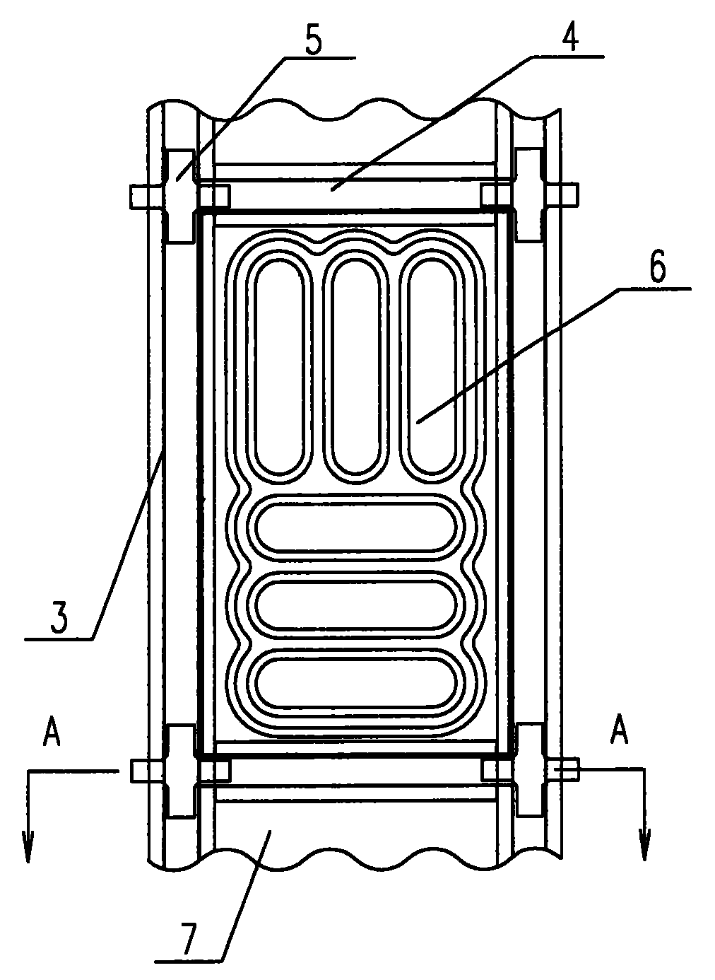
图2是单一框架结构示意图;Fig. 2 is a schematic diagram of a single frame structure;
图3是图2中的A-A向剖面图;Fig. 3 is A-A to sectional view among Fig. 2;
图4是所述内层筋板的平面和侧向结构对比图;Fig. 4 is the planar and lateral structural contrast diagram of described inner rib;
图5是所述立柱的平面和截面结构对比图;Fig. 5 is the planar and cross-sectional structure comparison diagram of described column;
图6是所述横梁的平面和截面结构对比图;Fig. 6 is the planar and cross-sectional structure comparison diagram of described beam;
图7是所述联结板的平面和侧面结构对比图;Fig. 7 is a plane and a side structure comparison diagram of the connecting plate;
图8是所述外板的结构图;Fig. 8 is a structural diagram of the outer plate;
图9和图10分别是具有其他形状的环状凸起的内层筋板示意图。Fig. 9 and Fig. 10 are respectively schematic diagrams of inner ribs with annular protrusions of other shapes.
如图1至图8所示,侧墙1,车窗2,立柱3,横梁4,联结板5,内层筋板6,外板7,筋板环状凸起8,点固或点焊加工点9。As shown in Fig. 1 to Fig. 8, side wall 1,
具体实施方式Detailed ways
实施例1,如图1至图8所示,所述轨道车辆的车体侧墙1具有,由若干个垂直立柱3和水平横梁4相互搭接构成的侧墙骨架,在每一搭接处连接有联结板5。Embodiment 1, as shown in Figures 1 to 8, the car body side wall 1 of the rail vehicle has a side wall skeleton composed of several
在每一骨架框架内,连接有一整体式的内层筋板6。In each skeleton frame, an integral
在侧墙骨架和内层筋板6的外部,通过点焊连接有一层外板7。On the outside of the side wall frame and the
在生产加工时,以整体冲压成形的内层筋板6来替代现有的板梁补强的结构方式。During production and processing, the existing plate girder reinforcement structure is replaced by the integrally stamped and formed
先将点焊成形的长方型框架定位,然后将内层筋板6点固在这个框架之间。Position the rectangular frame formed by spot welding first, and then fix the inner rib plate at 6 points between the frame.
如图3所示,在点固或点焊加工点9,将外板7、内层筋板6和骨架加工成一个统一体。As shown in Fig. 3, at the
通过拉延成型加工成形的内层筋板6,可以选用不锈钢材质。The
如图4所示,所述的内层筋板6,其侧面设置有呈垂直方向和水平方向排列的环状凸起8,两组环状凸起8的外缘彼此相连而形成为一整体式结构。As shown in Figure 4, the side of the
也可以采用如下结构方案,如图9所示,所述的内层筋板6,其侧面设置有一组呈水平方向排列的环状凸起8。The following structural scheme can also be adopted. As shown in FIG. 9 , the
或者,如图10所示,所述的内层筋板6,是在其侧面设置一组呈垂直方向排列的环状凸起8。Alternatively, as shown in FIG. 10 , the
Claims (8)
Priority Applications (1)
| Application Number | Priority Date | Filing Date | Title |
|---|---|---|---|
| CNU2006201579370U CN200988491Y (en) | 2006-11-13 | 2006-11-13 | Side wall structure of railway vehicle body |
Applications Claiming Priority (1)
| Application Number | Priority Date | Filing Date | Title |
|---|---|---|---|
| CNU2006201579370U CN200988491Y (en) | 2006-11-13 | 2006-11-13 | Side wall structure of railway vehicle body |
Publications (1)
| Publication Number | Publication Date |
|---|---|
| CN200988491Y true CN200988491Y (en) | 2007-12-12 |
Family
ID=38939532
Family Applications (1)
| Application Number | Title | Priority Date | Filing Date |
|---|---|---|---|
| CNU2006201579370U Expired - Lifetime CN200988491Y (en) | 2006-11-13 | 2006-11-13 | Side wall structure of railway vehicle body |
Country Status (1)
| Country | Link |
|---|---|
| CN (1) | CN200988491Y (en) |
Cited By (6)
| Publication number | Priority date | Publication date | Assignee | Title |
|---|---|---|---|---|
| CN102019937A (en) * | 2010-11-26 | 2011-04-20 | 中国北车集团大连机车车辆有限公司 | Urban rail stainless steel vehicle partitioning side wall module |
| CN103010237A (en) * | 2011-09-23 | 2013-04-03 | 南车青岛四方机车车辆股份有限公司 | Railway vehicle side wall and welding method thereof |
| CN106428055A (en) * | 2016-10-31 | 2017-02-22 | 中车齐齐哈尔车辆有限公司 | Side wall plate of wagon and wagon provided with side wall plate |
| CN109050553A (en) * | 2018-09-26 | 2018-12-21 | 重庆中车长客轨道车辆有限公司 | A kind of railcar and its headstock and skeleton |
| CN111806480A (en) * | 2020-07-28 | 2020-10-23 | 中车青岛四方机车车辆股份有限公司 | Rail vehicle side wall and rail vehicle |
| CN113002575A (en) * | 2021-01-04 | 2021-06-22 | 中车青岛四方机车车辆股份有限公司 | Modularized assembly welding structure and method for side wall unit of rail vehicle |
-
2006
- 2006-11-13 CN CNU2006201579370U patent/CN200988491Y/en not_active Expired - Lifetime
Cited By (8)
| Publication number | Priority date | Publication date | Assignee | Title |
|---|---|---|---|---|
| CN102019937A (en) * | 2010-11-26 | 2011-04-20 | 中国北车集团大连机车车辆有限公司 | Urban rail stainless steel vehicle partitioning side wall module |
| CN103010237A (en) * | 2011-09-23 | 2013-04-03 | 南车青岛四方机车车辆股份有限公司 | Railway vehicle side wall and welding method thereof |
| CN103010237B (en) * | 2011-09-23 | 2015-12-02 | 南车青岛四方机车车辆股份有限公司 | Rail vehicle side wall and welding method thereof |
| CN106428055A (en) * | 2016-10-31 | 2017-02-22 | 中车齐齐哈尔车辆有限公司 | Side wall plate of wagon and wagon provided with side wall plate |
| CN109050553A (en) * | 2018-09-26 | 2018-12-21 | 重庆中车长客轨道车辆有限公司 | A kind of railcar and its headstock and skeleton |
| CN111806480A (en) * | 2020-07-28 | 2020-10-23 | 中车青岛四方机车车辆股份有限公司 | Rail vehicle side wall and rail vehicle |
| CN113002575A (en) * | 2021-01-04 | 2021-06-22 | 中车青岛四方机车车辆股份有限公司 | Modularized assembly welding structure and method for side wall unit of rail vehicle |
| CN113002575B (en) * | 2021-01-04 | 2023-03-03 | 中车青岛四方机车车辆股份有限公司 | Modularized assembly welding structure and method for side wall unit of rail vehicle |
Similar Documents
| Publication | Publication Date | Title |
|---|---|---|
| CN201907513U (en) | Stainless steel rail passenger train body | |
| CN202593527U (en) | Sunken air conditioner installation structure of railway vehicle | |
| CN103287509B (en) | A kind of Lightweight coach body structure | |
| CN110466550B (en) | Rail vehicle side wall structure and rail vehicle | |
| CN203439041U (en) | Sidewall panel beam structure of light rail vehicle | |
| CN202324341U (en) | Cross-tank-shaped composite steel column | |
| CN202413808U (en) | Railway vehicle side wall | |
| CN201494452U (en) | Roof and side wall connection structure for rail vehicles | |
| CN102079315A (en) | Flat wagon center sill | |
| JP5986190B2 (en) | Rail vehicle structure | |
| CN201416231Y (en) | A composite I-beam | |
| CN201224409Y (en) | Stainless steel subway side wall framework module | |
| CN201411789Y (en) | H-shaped beam and H-shaped column weak axis connection node | |
| CN111071342B (en) | Electric automobile white automobile body rear end coupling assembling | |
| CN203391782U (en) | Roof structure of subway vehicle without side beams | |
| CN201856769U (en) | Stainless steel rail vehicle side wall blank window structure | |
| CN112026808B (en) | Side wall unit, vehicle body and rail vehicle | |
| CN207015453U (en) | A kind of front floor body structure of vehicle | |
| CN203246507U (en) | Vehicle body reinforcing structure | |
| CN112026809A (en) | End side wall structure, vehicle body, and rail vehicle | |
| CN202163445U (en) | Bottom frame for automatic dumper on railway | |
| CN202449080U (en) | Strengthening structure for automobile floor framework | |
| CN110065509B (en) | Car body door corner structure, car body and rail train | |
| CN202029858U (en) | Railway tub gondola car side wall assembly | |
| CN201646866U (en) | A connection assembly connecting the longitudinal beam of the automobile and the side beam of the front wheel house |
Legal Events
| Date | Code | Title | Description |
|---|---|---|---|
| C14 | Grant of patent or utility model | ||
| GR01 | Patent grant | ||
| C56 | Change in the name or address of the patentee |
Owner name: CSR, QINGDAO SIFANG RAILWAY CO., LTD. Free format text: FORMER NAME: CSR SIFANG RAILWAY CO., LTD. |
|
| CP03 | Change of name, title or address |
Address after: Qingdao, Chengyang District, Shandong City, Hong Hu Zhen, zip code: 266111 Patentee after: CSR Qingdao Sifang Locomotive and Rolling Stock Co., Ltd. Address before: Qingdao, Chengyang District, Shandong City, Hong Hu Zhen, zip code: 266111 Patentee before: CSR Sifang Locomotive and Rolling Stock Co., Ltd. |
|
| CX01 | Expiry of patent term |
Granted publication date: 20071212 |
|
| EXPY | Termination of patent right or utility model |