CN200939124Y - Endoscope apparatus - Google Patents
Endoscope apparatus Download PDFInfo
- Publication number
- CN200939124Y CN200939124Y CNU2006200017874U CN200620001787U CN200939124Y CN 200939124 Y CN200939124 Y CN 200939124Y CN U2006200017874 U CNU2006200017874 U CN U2006200017874U CN 200620001787 U CN200620001787 U CN 200620001787U CN 200939124 Y CN200939124 Y CN 200939124Y
- Authority
- CN
- China
- Prior art keywords
- image
- endoscope
- card
- endoscope apparatus
- cpu
- Prior art date
- Legal status (The legal status is an assumption and is not a legal conclusion. Google has not performed a legal analysis and makes no representation as to the accuracy of the status listed.)
- Expired - Lifetime
Links
Images


Classifications
-
- G—PHYSICS
- G02—OPTICS
- G02B—OPTICAL ELEMENTS, SYSTEMS OR APPARATUS
- G02B23/00—Telescopes, e.g. binoculars; Periscopes; Instruments for viewing the inside of hollow bodies; Viewfinders; Optical aiming or sighting devices
- G02B23/24—Instruments or systems for viewing the inside of hollow bodies, e.g. fibrescopes
- G02B23/2476—Non-optical details, e.g. housings, mountings, supports
- G02B23/2484—Arrangements in relation to a camera or imaging device
-
- A—HUMAN NECESSITIES
- A61—MEDICAL OR VETERINARY SCIENCE; HYGIENE
- A61B—DIAGNOSIS; SURGERY; IDENTIFICATION
- A61B1/00—Instruments for performing medical examinations of the interior of cavities or tubes of the body by visual or photographical inspection, e.g. endoscopes; Illuminating arrangements therefor
- A61B1/00002—Operational features of endoscopes
- A61B1/0002—Operational features of endoscopes provided with data storages
- A61B1/00022—Operational features of endoscopes provided with data storages removable
-
- A—HUMAN NECESSITIES
- A61—MEDICAL OR VETERINARY SCIENCE; HYGIENE
- A61B—DIAGNOSIS; SURGERY; IDENTIFICATION
- A61B1/00—Instruments for performing medical examinations of the interior of cavities or tubes of the body by visual or photographical inspection, e.g. endoscopes; Illuminating arrangements therefor
- A61B1/00002—Operational features of endoscopes
- A61B1/00039—Operational features of endoscopes provided with input arrangements for the user
- A61B1/0004—Operational features of endoscopes provided with input arrangements for the user for electronic operation
-
- A—HUMAN NECESSITIES
- A61—MEDICAL OR VETERINARY SCIENCE; HYGIENE
- A61B—DIAGNOSIS; SURGERY; IDENTIFICATION
- A61B1/00—Instruments for performing medical examinations of the interior of cavities or tubes of the body by visual or photographical inspection, e.g. endoscopes; Illuminating arrangements therefor
- A61B1/00002—Operational features of endoscopes
- A61B1/00043—Operational features of endoscopes provided with output arrangements
- A61B1/00045—Display arrangement
- A61B1/0005—Display arrangement combining images e.g. side-by-side, superimposed or tiled
-
- A—HUMAN NECESSITIES
- A61—MEDICAL OR VETERINARY SCIENCE; HYGIENE
- A61B—DIAGNOSIS; SURGERY; IDENTIFICATION
- A61B1/00—Instruments for performing medical examinations of the interior of cavities or tubes of the body by visual or photographical inspection, e.g. endoscopes; Illuminating arrangements therefor
- A61B1/04—Instruments for performing medical examinations of the interior of cavities or tubes of the body by visual or photographical inspection, e.g. endoscopes; Illuminating arrangements therefor combined with photographic or television appliances
- A61B1/042—Instruments for performing medical examinations of the interior of cavities or tubes of the body by visual or photographical inspection, e.g. endoscopes; Illuminating arrangements therefor combined with photographic or television appliances characterised by a proximal camera, e.g. a CCD camera
Abstract
An endoscope device in which endoscope images and patient information can be recorded in a removable storage medium and in which the endoscope images and patient information recorded in the storage medium can be reproduced. The endoscope device has a selection means for reproducing the endoscope images in a list form and selecting at least one endoscope image from the reproduced list; a displaymeans for inputting additional information other than the patient information, adding the additional information to the endoscope image selected by the selection means, and displaying the result; and a recording/reproduction means for recording the selected endoscope image and the additional information in the storage medium or reproducing the image and the information.
Description
Technical field
This utility model relates to endoscope apparatus, and in more detail, relating to the reproducing part that is recorded in the endoscopic images in the dismounting storage medium freely is the endoscope apparatus of feature.
Background technology
In recent years, endoscope is used widely in medical field and industrial field.And, recently, belt endoscope outside the television camera that the television camera with image unit has been installed in the eyepiece portion of optical profile type endoscope or be equipped with the endoscope apparatus that the captured endoscopic images of fujinon electronic video endoscope of image unit is presented on the monitor at leading section and also be used widely.
For this endoscope apparatus, many types that can be recorded in the endoscopic images that uses endoscope to photograph the technology that in the dismounting storage medium freely, also can reproduce that have had been proposed in the past.
For example, in the endoscope information recording system of Japanese kokai publication hei 6-96170 communique record, disclosed following technology: by image information that image fetching unit read and the audio information recording that reads by the sound reading unit in blocking the shape recording medium.
And the endoscopic system of putting down in writing in Japanese kokai publication hei 11-89792 communique has carry out the apparatus for processing of video signals of signal processing from the image pickup signal of endoscope.The video signal output control unit that this apparatus for processing of video signals has is being detected under the situation of being installed to as the PC card of storage medium on the PC draw-in groove by the card detecting unit at least, from the signal processing unit that described image pickup signal is handled, the memory control unit outputting video signal to the memorizer that the freeze frame of endoscopic images is stored in the PC card, record in the described PC card.
And, disclosed following technology in the endoscope image pick-up device of Japanese kokai publication hei 11-32983 communique record: this endoscope image pick-up device has the storage card of the external memory unit of a plurality of regulons of the adjusting of carrying out the video signal characteristic in the signal processing unit and the regulated value that this regulon is stored in conduct, by control unit, set according to being stored in the action that regulated value in the storage card changes described regulon.
In recent years, for this endoscope apparatus, in order to analyze effectively in the image sets of service recorder after the inspection in recording mediums such as PC card or storage card and to diagnose, select a plurality of desired images in the image sets of wishing from described recording medium, to write down, show or print as 1 width of cloth image.
Yet, in described prior art, has following problem, promptly under the situation that the image that writes down in reading recording mediums such as PC card or storage card reproduces, the guide look demonstration or the full frame that can only carry out breviary demonstration etc. show, selects a plurality of images of expectation in the image sets that can not store and show or print as 1 width of cloth image from described storage medium.
And, in order to analyze effectively and to diagnose, wish for selected image, the additional information beyond the remarks patient information from behind, note for example, however in described prior art, have can not the remarks note problem.
[patent documentation 1] Japanese kokai publication hei 6-96170 communique
[patent documentation 2] Japanese kokai publication hei 11-89792 communique
[patent documentation 3] Japanese kokai publication hei 11-32983 communique
The utility model content
Therefore, this utility model is In view of the foregoing to propose, and the purpose of this utility model provides a kind of endoscope apparatus, selects a plurality of images the image sets that can store in storage medium, and shows or record as 1 width of cloth image with note.
According to endoscope apparatus of the present utility model can be in dismounting storage medium freely storage endoscope image and patient information, perhaps can reproduce the described endoscopic images and the patient information of record in the described storage medium, this endoscope apparatus has: selected cell, its form with catalog is reproduced a plurality of described endoscopic images, and selects at least one endoscopic images from the catalog of this reproduction; Display unit, it imports the additional information beyond the described patient information, and is attached on the endoscopic images of being selected by described selected cell and shows; And the record-playback unit, it is recorded in the endoscopic images of described selection and described additional information in the described storage medium or reproduces.
Description of drawings
Fig. 1 illustrates the 1st embodiment of endoscope apparatus of the present utility model, is the integrally-built block diagram that endoscope apparatus is shown.
Fig. 2 is the front elevation of surface structure that the video processor of Fig. 1 is shown.
Fig. 3 is the vertical view of surface structure that the keyboard of Fig. 1 is shown.
Fig. 4 illustrates the key diagram that is used to the operating procedure selecting image and make up annotating images.
Fig. 5 is illustrated in the key diagram that the annotating images that makes up among Fig. 4 is recorded the folder structure under the interior situation of storage card.
Fig. 6 illustrates the 2nd embodiment of endoscope apparatus of the present utility model, is the block diagram of schematic configuration that the video processor of endoscope apparatus is shown.
Fig. 7 illustrates the variation of the access LED of the 2nd embodiment, is the block diagram of structure that the containing section of video processor 4 is shown.
Fig. 8 is used for the key diagram that the 3rd embodiment to endoscope apparatus of the present utility model describes.
Fig. 9 is used for the key diagram that the variation to the 3rd embodiment describes.
Figure 10 is used for the key diagram that the 4th embodiment to endoscope apparatus of the present utility model describes.
Figure 11 illustrates the 5th embodiment of endoscope apparatus of the present utility model, is the block diagram of major part that the video processor of endoscope apparatus is shown.
Figure 12 is the figure that the demonstration example of monitor is shown.
Figure 13 describes the variation of the 5th embodiment, is the key diagram that the treatment step of CPU is shown.
Figure 14 illustrates the filename that the processing according to Figure 13 generates and the figure of endoscopic images.
Figure 15 illustrates the 6th embodiment of endoscope apparatus of the present utility model, is the flow chart that the control example of the CPU in this endoscope apparatus is shown.
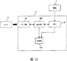
Figure 16 is the block diagram of major part variation, video processor that the endoscope apparatus of the 1st to the 6th embodiment is shown.
The specific embodiment
Below, with reference to accompanying drawing embodiment of the present utility model is described.
<the 1 embodiment 〉
Fig. 1 illustrates the 1st embodiment of endoscope apparatus of the present utility model, is the integrally-built block diagram that endoscope apparatus is shown.As shown in Figure 1, the endoscope apparatus 1 of present embodiment has: fujinon electronic video endoscope (being designated hereinafter simply as endoscope) 2, light supply apparatus 3, video processor 4, observation monitor (hereinafter referred to as monitor) 5, video printer 6, keyboard 7, mouse 8, USB storage 9 and storage card (PC card) 10.
Endoscope 2 is inserted in the body cavity, is used for making a video recording in the body cavity.Light supply apparatus 3 produces the illumination light of observing usefulness.4 pairs of endoscopies of video processor, 2 taken picture signals are carried out signal processing.Monitor 5 shows endoscopic images.Video printer 6 is printed endoscopic images.Keyboard 7 and mouse 8 carry out the operation indication and the data input of endoscope apparatus integral body.USB storage 9 be can be on video processor 4 dismounting storage medium freely.PC card 10 be can be on video processor 4 dismounting storage medium freely.
In addition, described light supply apparatus 3 constitutes one with described video processor 4, yet also can be split.
Described endoscope 2 has: insert endoceliac insertion section 2A with elongated shape, and the operating portion 2B that is arranged on the rear end of this insertion section 2A.
In the 2A of this insertion section, penetratingly inserted the photoconduction 16 that transmits illumination light.Optical connector 14 dismounting of the rear end of this photoconduction 16 are connected on the light supply apparatus 3 freely.And optical connector 14 transmits the illumination light of supplying with from light supply apparatus 3.The illumination light of this transmission is further passed through illuminating lens 17, the subject 2C side of the endoceliac affected part that throws light on etc. from the front end face on the illuminating window (not shown) of the leading section 2a that is installed in insertion section 2A.
On this leading section 2a, be provided with the observation window (not shown) in abutting connection with ground with illuminating window, objective lens optical system 18 is installed on this observation window.On the image space of this objective lens optical system 18, form the optical image of illuminated subject 2C.This image space is provided with the CCD 19 as solid-state imager, and the optical image of imaging is carried out opto-electronic conversion.
This CCD 19 is electrically connected with video processor 4 via running through the holding wire, adapter 11, cable 12 and the adapter 13 that wait in the 2A of insertion section.Then, carry out the resulting picture signal of opto-electronic conversion (image pickup signal) by CCD 19 and be set at 20 amplifications of the interior amplifier of leading section 2a.Afterwards, this image pickup signal outputs to video processor 4 via described holding wire, adapter 11, cable 12 and adapter 13.
And, in operating portion 2B of this endoscope 2 etc., be provided with CCD identifying information portion 22 and switch 21.CCD identifying information portion 22 stores the model information (for example identifying information of CCD etc.) of endoscope 2 and electronic shutter speed etc.Switch 21 is used to make this CCD 19 to be driven to carry out observing pattern.
Light supply apparatus 3 has lamp 23, light modulation portion 24 and dimming control part 25.Lamp 23 is xenon lamps of irradiates light etc.Light modulation portion 24 is arranged on the illumination path of this lamp 23, has a plurality of light filters, illumination light illumination aperture and rotary filter etc., regulates the illumination light quantity.Dimming control part 25 these light modulation portions 24 of control.
This dimming control part 25 is according to the control signal of supplying with via adapter 13, cable 12, adapter 11 and holding wire from the dimming control part 30 of video processor 4 described later, controls described light modulation portion 24.
And this video processor 4 constitutes picture signal is flowed according to the order of A/D change-over circuit 26, prime Video processing portion 27, isolation part 28, rear-class video handling part 31, pictorial display/overlapping 32 and D/A change-over circuit 34.
A/D change-over circuit 26 converts the image pickup signal from CCD 19 outputs to digital signal.27 pairs of view data from 26 outputs of A/D change-over circuit of prime Video processing portion are carried out pre-treatment.31 pairs of view data from isolation part 28 of rear-class video handling part are carried out post processing.Pictorial display/overlapping 32 pairs view data from this rear-class video handling part 31 are that USB storage 9 or storage card 10 interior view data are synthesized and overlapping processing with being stored in exterior storage medium described later.D/A change-over circuit 34 converts the digital signal from pictorial display/overlapping 32 output to analogue signal.
And, this video processor 4 has: dimming control part 30, catch portion 33, CPU 38, bus 39, RAM 40, flash memory 41, I/O port 42, panel 43, (PeriferalComponent Interconnect: Peripheral Component Interconnect) bus bridge 44 for PCI, pci bus 45, USB (Universal Serial Bus: USB (universal serial bus)) master controller 46, PC card controller 48 and UART (Universal Asynchronous Receiver Transmitter: the abbreviation of UART Universal Asynchronous Receiver Transmitter, hereinafter referred to as UART) 50.
The dimming control part 25 of the described light supply apparatus 3 of dimming control part 30 controls.Catching portion 33 catches from the view data of rear-class video handling part 31 or from the view data of storage mediums such as described storage card 10.CPU 38 carries out the various control actions of device integral body.Bus 39 is used for CPU 38 is coupled together with RAM 40, flash memory 41, I/O port 42 and pci bus bridge 44.Pci bus bridge 44, USB master controller 46, PC card controller 48, UART 50, catch portion 33 and pictorial display/be connected to pci bus 45 for overlapping 32.
And video processor 4 has: adapter 35, adapter 36, splicing ear 37, connecting portion 47 and slot 49.
In the video processor 4 of said structure, as shown in Figure 1, carry out the A/D conversion from the picture signal that CCD 19 obtains by A/D change-over circuit 26, and output to prime Video processing portion 27.
Afterwards, the view data behind the digitized is handled by the prime that prime Video processing portion 27 implements color separated etc., outputs to rear-class video handling part 31 afterwards after being isolated by isolation part 28.
The Video processing of in this rear-class video handling part 31, the view data supplied with being implemented that γ conversion, emphasizing contour and amplification are dwindled etc.Afterwards, view data with overlapping from the view data (also comprising OSD (On-Screen Display: show on the screen) display image) and the Word message of cpu circuit side described later, outputs to D/A change-over circuit 34 by pictorial display/overlapping 32.
In D/A change-over circuit 34 that the view data of being supplied with is simulated.View data after this is simulated outputs to monitor 5 and video printer 6 via described adapter 35,36.Like this, by the image (endoscopic images) of monitor 5 demonstrations based on the picture signal of being supplied with, and by the image of video printer 6 printings based on the picture signal of being supplied with.
In addition, in the present embodiment,,, as previously mentioned, in operating portion 2B of endoscope 2 etc., be provided with CCD identifying information portion 22 in order to drive the different a plurality of CCD 19 of drive condition such as pixel count for endoscope apparatus 1.Video processor 4 uses the identifying information that is stored in this CCD identifying information portion 22 to control, with the drive condition of change CCD 19 and the processing parameter of described rear-class video handling part 31.
And, in the present embodiment, as previously mentioned,, in described light supply apparatus 3, be provided with light modulation portion 24 and dimming control part 25 in order to keep the illumination condition of subject 2C best.This light modulation portion 24 and dimming control part 25 are by 30 controls of the dimming control part in the video processor 4, thus adjusting illumination light intensity.
As shown in Figure 1, the output image data from described rear-class video handling part 31 also is provided for the portion of catching 33.This is caught portion 33 and is connected with described pci bus 45.This is caught portion 33 and is taken into the endoscopic images data, and outputs to cpu circuit side described later via described pci bus 45.
Cpu circuit is made of following as previously mentioned: CPU 38, bus 39, and RAM 40, flash memory 41, I/O port 42, pci bus bridge 44, pci bus 45, USB controller 46, PC card controller 48 and UART 50.
The control that described cpu circuit carries out video processor 4 inside with the communicating by letter of external equipment.
Described CPU 38 is connected with RAM 40, flash memory 41 and I/O port 42 by bus 39.
Described panel 43 is connected with this I/O port 42.This panel 43 is provided with switch and the LED that image quality is regulated usefulness.This panel 43 is perhaps controlled LED by this LED and is shown by the input of this switch reception from user.
And described pci bus bridge 44 is connected on the bus 39 of described CPU 38.This pci bus bridge 44 converts the bus 39 of described CPU 38 to as versabus pci bus 45.On this pci bus 45, be connected with described capture circuit 33, USB controller 46, PC card controller 48 and UART 50.
Described USB controller 46 is to be used for the circuit that is connected with external USB equipment by connecting portion 47.Human interface device) and USB storage 9 (StorageDevice for example: memory device) as USB device in the present embodiment, described USB controller 46 connects HID (the HumanInterface Device: of keyboards 7 and mouse 8.
In addition, described connecting portion 47 has adapter 47a, adapter 47b and adapter 47c.Adapter 47a is used to connect keyboard 7.Adapter 47b is used to connect the HID of mouse 8.Adapter 47c is used to connect USB storage 9.
Described PC card controller 48 is connected with PC draw-in groove 49 in being arranged on video processor 4, and storage card 10 that can dismounting on this PC draw-in groove 49 is controlled.Described UART 50 is the circuit that are used for carrying out with external equipment serial communication, in the present embodiment, is used for video printer 6 equipment such as grade are carried out Long-distance Control.
Fig. 2 is the front elevation of surface structure that the video processor of Fig. 1 is shown.As shown in Figure 2, the video processor 4 of said structure has main body 4A.Front at this main body 4A is provided with front panel 4B.
Left end in Fig. 2 of this front panel 4B is provided with the on and off switch 51 of the power supply that is used to drop into video processor 4.Near this on and off switch 51, be provided with endoscope and connect adapter 52 (in Fig. 1, being equivalent to adapter 13).Endoscope connects the adapter (not shown) that adapter 52 is used to connect the base end part of the cable 12 that is arranged on described endoscope 2.
And the right side branch is provided with white balance switch 53 among the figure of pro-panel 4B.White balance switch 53 is used to regulate the white balance of monitor 5, and the right side branch is provided with light quantity by-pass cock 54 and LED 54a in the figure of this white balance switch 53.Light quantity by-pass cock 54 is used to regulate the light quantity of light supply apparatus 3.LED 54a is used for showing its rank when light quantity is regulated.
And, be provided with the image selector switch 55 that is used to select input picture among the figure of pro-panel 4B near the central authorities.
This image selector switch 55 left side from figure has for example a plurality of switches of SCOPE (endoscope 2), DV/VCR, PC (storage card 10), PRINTER (video printer 6), PinP (image of the picture-in-picture that monitor 5 shows) etc.Be respectively arranged with on the top of a plurality of switches and be used to allow user know just at work LED 55a.
Below image selector switch 55, be provided with reset switch 56, strengthen (image is emphasized) rank switch 57 and metering mode change-over switch 58.
And as previously mentioned, the front panel 4B of video processor 4 is provided with PC draw-in groove 62 (label 49 that is equivalent to Fig. 1).The right side is provided with and is used for the external image input connector 63 that is connected with external image equipment in the figure of this PC draw-in groove 62.
In the present embodiment, in the figure of described PC draw-in groove 62, be provided with PC card shutdown switch 59 and access demonstration LED 60 near the left side.
Described PC card shutdown switch 59 is when storage card 10 is installed on the described PC draw-in groove 62, in the middle of 38 pairs of described storage cards 10 of described CPU carry out access, is necessary to stop the switch of pressing under the situation of this access action owing to certain situation.
That is, user is pressed this PC card shutdown switch 59, and like this, CPU 38 discerns this, and control PC card controller 48 is to stop the access to storage card 10.
And described access shows that LED 60 carries out at 38 pairs of storage cards of described CPU 10 showing under the situation of access, thereby can allow user know just in access.
Fig. 3 is the vertical view of surface structure that the keyboard of Fig. 1 is shown.As shown in Figure 3, the keyboard 7 that is connected with video processor 4 of present embodiment has main body 7A.This main body 7A has: major key input part 7B, and the auxiliary bond input part 7C that is arranged on this major key input part 7B top.
Described major key input part 7B mainly has: enter key 70, function key 71, and VTR control key 74.
The switch of pressing when PC card display key 73 is images of storage in showing storage card 10 etc.In addition, VTR control key 74 is to be used for the switch when being connected on the video processor 4 this VTR controlled to unshowned VTR.
Described auxiliary bond input part 7C has: sensing portion 75, printer control key 78, tone key 79, freezing key 81, release key 82 and inspection end key 83.
In the endoscope apparatus 1 of present embodiment, carry out the data input by the keyboard 7 that uses said structure by user, can append to the information (patient information) and the additional information of patient's name etc. on the endoscopic images data.
And endoscope apparatus 1 can record these information in storage card 10 or the USB storage 9 with view data.
And endoscope apparatus 1 can communicate with the external equipment of video printer 6 grades, and equally can be with described information with the view data record.In addition, the indication of the record of this moment can be carried out by the switch of the switch 21 on the operating portion 2B that is arranged on endoscope 2 and keyboard 7 or panel 43.
And as previously mentioned, described keyboard 7 is provided with PC card display key 73.When pressing this PC card display key 73, CPU 38 control PC card controllers 48 or USB master controller 46 are read view data from storage card 10 or USB storage 9 as storage medium, can pass through pictorial display/overlapping 32, display image data and information on monitor 5.
In addition, the endoscope apparatus 1 of present embodiment can be when reading and reproduce the image of storing in the recording medium such as storage card 10, selects a plurality of images of expectation the image sets of storing and show or print as 1 width of cloth image in described storage medium.
And, endoscope apparatus 1 can as the note of effectively analyzing and diagnosing required patient information and additional information from behind remarks in the image of described selection.
In addition, in the present embodiment, show or print about a plurality of images of selecting expectation and as 1 width of cloth image, and as the note of effectively analyzing and diagnosing required patient information and the additional information function of remarks in the image of described selection from behind, hereinafter referred to as annotation function.
With reference to Fig. 4 and Fig. 5 the annotation function of this endoscope apparatus 1 is described.
Use Fig. 4 and Fig. 5 that the annotation function of the endoscope apparatus 1 of present embodiment is described.Fig. 4 illustrates to be used to select image to make up the key diagram of the operating procedure of annotating images.Fig. 5 is illustrated in the key diagram that the annotating images that makes up among Fig. 4 is recorded the folder structure under the situation in the storage card.
As shown in Figure 4, in the endoscope apparatus 1 of present embodiment, when pressing PC card display key 73 for example shown in Figure 3 and carry out annotation function, as previously mentioned, described CPU 38 control PC card controllers 48 or USB master controller 46 are read view data and information from storage card 10 or USB storage 9 as storage medium, via pictorial display/overlapping 32, on monitor 5, show the note picture 5A with a plurality of images for example shown in Figure 4.
Note picture 5A has as shown in Figure 4: location of annotated information specifying part 90, " View " button 91, " Cancel " button 92, cursor 93, and image display area 94.
Location of annotated information specifying part 90 is used to select annotating images." View " button 91 is used to carry out the image of selecting by this location of annotated information specifying part 90." Cancel " button 92 is used to cancel this selection operation.Cursor 93 is used on this note picture 5A image being selected and the button execution is operated.In image display area 94, show a plurality of images.
Described location of annotated information specifying part 90 is selected for example 4 images, has respectively and specifies corresponding specifying part 90a, 90b, 90c, 90d with location of annotated information.
In this case, described specifying part 90a is used for selecting image in the picture top-left position, and described specifying part 90b is used for selecting image in the picture upper-right position.Equally, described specifying part 90c is used at picture lower-left choice of location image, and described specifying part 90d is used at picture bottom right choice of location image.
In addition, in the present embodiment, described 4 specifying part 90a~90d are divided into different colours, for example, described specifying part 90a is set at redness (among the figure shown in the horizontal line), described specifying part 90b is set at blueness (among the figure shown in the vertical line), described specifying part 90c is set at green (right tiltedly shown in the oblique line among the figure), and described specifying part 90d is set at yellow (among the figure shown in the oblique oblique line in a left side).Like this, can discern location of annotated information at a glance.
User uses the sensing portion 75 or the mouse 8 (with reference to Fig. 1) of keyboard 7 shown in Figure 3 in next note picture 5B, make cursor 93 aim at specifying part 90a.
Like this, the CPU 38 of video processor 4 carries out the preference pattern of the image that is provided with on the position corresponding with this specifying part 90a.That is, shown in next note picture 5C, CPU 38 is along with cursor 93 moves, and display image is selected cursor 90A in image display area 94.
Then, when for example supposing that desired image is image 94a, user is aimed at this image 94a by making described cursor 93, utilizes described image to select cursor 90A to specify this image 94a, and presses executive button 76 (with reference to Fig. 3) and determine.
Then, user uses the sensing portion 75 or the mouse 8 (with reference to Fig. 1) of keyboard 7 shown in Figure 3 in next note picture 5D, makes cursor 93 aim at specifying part 90b.
Like this, described CPU 38 carries out the preference pattern of the image that is provided with on the position corresponding with this specifying part 90b with above-mentioned same.That is, shown in note picture 5D, CPU 38 is along with cursor 93 moves, and display image is selected cursor 90B in image display area 94.
Then, when for example supposing that desired image is image 94b, user is aimed at this image 94b by making described cursor 93, utilizes described image to select cursor 90B to specify this image 94b, and presses executive button 76 (with reference to Fig. 3) and determine.
Afterwards, for described specifying part 90c, 90d, also select action similarly to select image with above-mentioned image.
And when the image of finishing the 4th specifying part 90d was selected action, user made cursor 93 aim at " View " button 91, by pressing executive button 76 (with reference to Fig. 3), finished the image of annotating images and selected.
Like this, CPU 38 on the position specified by described specifying part 90a~90d, and generates the additional note picture 5J that patient information and note are arranged to selected image setting based on view data, is presented on the monitor 5.
That is, as shown in Figure 4, described note picture 5J has: viewing area 97, annotating images viewing area 98, note viewing area 99, " Save " button 95, " Print " button 96, and " Cancel " button 92.
The related information (patient information) that in viewing area 97, shows this annotating images.Annotating images viewing area 98 is made of 4 image 94a~94d that are presented on the assigned address.Note viewing area 99 is arranged on the picture bottom, is the zone that is used to show at the notes such as note of this annotating images." Save " button 95 is used for carrying out executable operations based on the view data of this note picture 5J and the storage of note." Print " button 96 is used for this note picture 5J is printed indication.
In addition, in the present embodiment,, just can use keyboard 7 grades to insert the note 99a of note etc., perhaps edit as long as specify described note viewing area 99 and carry out by cursor 93.
And, in the present embodiment, select the situation of 4 annotating images to be described to using 4 specifying part 90a~90d, yet be not limited thereto, also can freely be set at for example desired quantity of user of 3 grades.
And user makes described cursor 93 aim at " Print " button 96 under the situation of printing note picture 5J shown in Figure 4, presses executive button 76 (with reference to Fig. 3).
Like this, CPU 38 controls, and communicating by UART 50, thereby prints offering video printer 6 based on the view data of this note picture 5J and information.
And under situation about note picture 5J shown in Figure 4 being stored in the storage card 10, user makes described cursor 93 aim at " Save " button 95, presses executive button 76 (with reference to Fig. 3).
Like this, CPU 38 control PC card controller 48 or USB master controllers 46 are to store view data and information based on this note picture 5J in storage card 10 or the USB storage 9 into.
Fig. 5 is illustrated in the folder structure under the situation about storing into based on the view data of described annotating images and information in the storage card 10.
The video processor 4 of present embodiment as shown in Figure 5 according to folder structure, carries out the record of view data and note at storage card 10 with the hypertext form.
In addition, video processor 4 use well-known DCF (Design rule for CameraFile system: digital camera picture format photographing unit Design of File Systems rule), further carry out the record of note.
For example, 38 pairs of storage cards 10 of CPU are controlled, and with as shown in Figure 5, generate: the 1st file 10A of " DCIM " and " INDEX.HTM " etc.; Press from both sides the 2nd file 10B that constitutes by image folder and comment file; And, store the 3rd file 10C of each image file and each comment file as the lower floor of the 2nd file 10B.
Described the 2nd file 10B has: store image folder 10b1, the 10b2 of a plurality of image files of each time inspection, and the comment file folder 10b3 that stores the annotating images (also comprising note) that generates by annotation function.
In addition, when each the inspection, generate, increase described image folder 10b1,10b2.And,, when carrying out annotation function at every turn, generate, increase too for described comment file folder 10b3.
In this case, as shown in Figure 5, when if the folder name of image folder 10b1 is " 001AAAA ", in the file of this " 001AAAA ", store the image file that " AAAA0001:JPG " (JPG compressed image), " AAAA0001.THM " (thumbnail image) or " AAAA0001.GIF " (the non-compressed image of TIFF) etc. in the 3rd file 10C are checked for 1 time.
And, when if the folder name of image folder 10b2 is " 999ZZZZ ", in the file of this " 999ZZZZ ", store the image file that " ZZAA0001.JPG " (JPG compressed image), " ZZAA0001.THM " (thumbnail image) or " ZZAA0001.GIF " (the non-compressed image of TIFF) etc. in the 3rd file 10C are checked for 1 time.
Then, in the present embodiment, if the folder name of comment file folder 10b3 is " ANN0001 " time, in the file of this " ANN0001 ", store selected 4 images, for example " AAAA0001.JPG " (JPG compressed image), " AAAA0002.JPG " (JPG compressed image), " AAAA0003.JPG " (JPG compressed image), " AAAA0004.JPG " (JPG compressed image) and as the comment file " ANN00001.HTM " (html file) of remarks information.
In addition, in described the 1st file 10A " INDEX.HTM ", the data such as guide look information of complete inspection have been stored as html file.
Therefore, according to present embodiment, as previously mentioned, by carrying out annotation function, can from the image sets in being stored in storage card 10 storage mediums such as grade, select a plurality of images and show or record as 1 width of cloth image, thereby can examine effectively and analyze with note.
And, as shown in Figure 5,,, also can reproduce and show the view data and the note of the storage card 10 that is write down even use personal computer by additional annotations when using DCF, ease of use improves.
And, usually when 4 width of cloth images being rebuild when being 1 width of cloth image, sometimes produce the influence of image quality deterioration etc., yet in the present embodiment, because selected 4 image files carry out record according to file originally, note also comes record according to html file simultaneously, thereby can not produce the image quality deterioration, but the image of clear display and information.
<the 2 embodiment 〉
Fig. 6 illustrates the 2nd embodiment of endoscope apparatus of the present utility model, is the block diagram of schematic configuration that the video processor of endoscope apparatus is shown.
As shown in Figure 6, the PC draw-in groove 49 of video processor 4 is provided with ejector button 49a, and this ejector button 49a is used to force to eject the storage card 10 that is installed on this PC draw-in groove 49.User can force to eject storage card 10 by pressing this ejector button 49a.
Yet, ejecting storage card 10 if when storage card 10 carries out access, press ejector button 49a at CPU 38, the data that are stored in the storage card 10 may be damaged.And,,, data or storage card 10 itself are damaged if in power supply is supplied with, eject even not in access.
Therefore, in the present embodiment, as shown in Figure 6, on the front panel 4B of video processor 4, near PC draw-in groove 49, be provided with access shutdown switch 59 (identical) and access LED 60 with 59 effects of PC card shutdown switch.In addition, access shutdown switch 59 also can adopt PC card stop key 72 shown in Figure 3.
That is, by being pressed access shutdown switch 59 by user, CPU 38 discerns this, and control PC card controller 48 is to stop the access (data are read/write) to storage card 10.And in the present embodiment, CPU 38 control PC card power supply 48a cut off the power supply of PC draw-in groove 49 are supplied with.
Having or not of the access of 38 pairs of storage cards 10 of the described access LED 60 described CPU of demonstration is by described PC card controller 48 controls.
For example, PC card controller 48 makes access LED 60 bright lamps in access or under the situation in the power supply supply.On the other hand, make the access LED60 lamp that do not work in non-access or under the situation in the dump.Like this, owing to can allow user discern access situation and power supply state of supply at a glance, thereby can prevent that the mistake of using ejector button 49a to carry out from ejecting, can prevent the destruction of data in the storage card 10 and storage card 10 itself.
In addition, in the present embodiment, when supressing access stop button 59, can be controlled to the data of abandoning in writing, also may be controlled to writing and stop after processing finishes handling by CPU 38.
Therefore, according to present embodiment, except can obtaining the effect identical,, can also allow user discern access situation and power supply state of supply at a glance by access LED 60 is set with described the 1st embodiment.Like this, the mistake that can prevent to use ejector button 49a to carry out ejects, and can prevent the destruction of data in the storage card 10 and storage card 10 itself.
In addition, the access LED 60 of present embodiment can also constitute shown in the variation of Fig. 7.Fig. 7 illustrates the variation of the access LED of the 2nd embodiment, is the block diagram of structure that the containing section of video processor 4 is shown.
As shown in Figure 7, in this variation, between power control part 48b and PC draw-in groove 49, be connected with for example green access LED 60a via resistance R 1 by 48 controls of PC card controller.
And for example Hong Se access LED 60b is connected with described PC card controller 48 via resistance R 2.These 2 access LED 60a, 60b install by for example same encapsulation, and are arranged on the precalculated position of front panel 4B of video processor 4.
In addition, in this variation, use 2 access LED 60a, 60b, yet, can use 1 LED to constitute if use the LED that can 2 colors shows.
Therefore, according to this variation, except can obtaining the effect identical, can also allow user discern the working condition relevant at a glance with PC card controller 49 with the 2nd embodiment.
<the 3 embodiment 〉
Fig. 8 is used for the key diagram that the 3rd embodiment to endoscope apparatus of the present utility model describes.In addition, Fig. 8 pair of element mark identical label identical with described the 1st embodiment omits explanation.
Generally, expectation is that endoscope apparatus 1 can show the endoscopic images in the inspection of real-time demonstration simultaneously and the endoscopic images that has been recorded in the storage card 10 etc. compares.
In view of this requirement, the endoscope apparatus 1 of present embodiment constitutes, as shown in Figure 8, at the back side of video processor 4 4C (also can be front panel 4B side) real time imaging out connector 35A and PC card graphic out connector 35B are set, although not shown, they connect monitor 5,5X respectively.
Described real-time adapter 35A is equivalent to adapter shown in Figure 1 35.
In addition, the internal structure of video processor 4 and internal structure shown in Figure 1 are roughly the same, yet the graphics circuitry portion of another system can also be set on pci bus 45.That is, pictorial display/overlapping 32 and D/A change-over circuit 34 are connected on the pci bus shown in Figure 1 45, described PC card graphic out connector 35B is connected on this D/A change-over circuit 34.And newly-installed monitor 5X is connected with this PC card graphic out connector 35B.
Other structure is identical with above-mentioned the 1st embodiment.
In the endoscope apparatus 1 of said structure, the endoscopic images 100 that monitor 5 shows in checking, another monitor 5X shows the former endoscopic images 101 that is stored in the storage card 10.
Like this, can show the endoscopic images 100 in the inspection of real-time demonstration simultaneously and the endoscopic images 101 that has been recorded in the storage card 10 etc. compares, can more effectively check and analyze.
In addition, present embodiment also can constitute shown in the variation of Fig. 9.Fig. 9 is used for the key diagram that the variation to the 3rd embodiment describes.
As shown in Figure 9, in this variation, removed the PC card graphic out connector 35B of above-mentioned the 3rd embodiment, adopt the structure identical with video processor shown in Figure 14, by endoscopic images in the inspection of real-time demonstration 100 and the endoscopic images 101 that is recorded in storage card 10 grades are carried out picture-in-picture demonstration (PiP demonstration), show simultaneously to compare.
That is, video processor 4 carries out overlapping processing by pictorial display/overlapping 32 to endoscope's view data with from the PC view data of storage card, to become PiP picture shown in Figure 9, after the D/A conversion, outputs to monitor 5 via adapter 35.
Like this owing on monitor 5, show PiP picture shown in Figure 9, even thereby use 1 monitor 5, can show simultaneously that also endoscopic images 100 in the inspection of real-time demonstration and the endoscopic images 101 that is recorded in storage card 10 grades compare.
<the 4 embodiment 〉
Figure 10 (Figure 10 A, Figure 10 B, Figure 10 C) is used for the 4th embodiment of endoscope apparatus of the present utility model is described.Figure 10 A is the key diagram that is illustrated in the image that is write down under the situation of A-CCD.Figure 10 B is the key diagram that is illustrated in the image that is write down under the situation of B-CCD.Figure 10 C is the key diagram that is illustrated in the image that is write down under the situation of C-CCD.In addition, Figure 10 pair of element mark identical label identical with above-mentioned the 1st embodiment omits explanation.
Endoscope apparatus in the past is the length-width ratio that shows on the observation picture of monitor that 4: 3 picture is recorded in recording medium etc.
Yet under the situation of endoscope, the picture that is write down has the white space beyond octagonal endoscopic images and this endoscopic images, thereby when using this recording method, described white space also is recorded, thereby recording capacity is increased.Certainly, carrying out the demonstration of patient ID etc. sometimes in this white space, is waste yet write down same patient ID for all images.
Therefore, in the present embodiment, do not write down the picture of described white space etc., and the record endoscopic images corresponding with CCD only.
As shown in figure 10, usually, in endoscope apparatus, according to the pixel count of the CCD that carries in the endoscope, the viewing area difference of endoscope's picture.
Therefore, the endoscope apparatus of present embodiment 1 is differentiated the endoscope 2 (CCD 19) that is connected with video processor 4 according to the identifying information from described CCD identifying information portion 22.Promptly, the CPU 38 of video processor 4 is controlled to, and according to the identifying information from described CCD identifying information portion 22, differentiates the endoscope 2 (CCD 19) that is connected with video processor 4, and, endoscopic images is recorded in the storage card 10 according to corresponding with each CCD19 in advance masking regional.
For example, CPU 38 is that the endoscopic images 102 that shows on A-CCD, the observation picture is under the situation of the image of sheltering size shown in Figure 10 A differentiating for the CCD 19 of endoscope 2 according to described identifying information, control PC card controller 48 is only to be recorded in this endoscopic images 102 of sheltering size in the storage card 10.
And, CPU 38 is that the endoscopic images 103 that shows on B-CCD, the observation picture is under the situation of the image of sheltering size shown in Figure 10 B differentiating for the CCD 19 of endoscope 2 according to described identifying information, control PC card controller 48 is only to be recorded in this endoscopic images 103 of sheltering size in the storage card 10.
And, CPU 38 is that the endoscopic images 104 that shows on C-CCD, the observation picture is under the situation of the image of sheltering size of the whole image shown in Figure 10 C differentiating for the CCD 19 of endoscope 2 according to described identifying information, control PC card controller 48 is only to be recorded in this endoscopic images 104 of sheltering size (whole image) in the storage card 10.
Like this, can dwindle the image file that is recorded in the storage card 10.And, be under the situation of same size at the image file of record, also can improve image quality.
Other structure, effect and effect are identical with above-mentioned the 1st embodiment.
<the 5 embodiment 〉
Figure 11 and Figure 12 illustrate the 5th embodiment of endoscope apparatus of the present utility model.Figure 11 is the block diagram of major part that the video processor of endoscope apparatus is shown.Figure 12 is the figure that the demonstration example of monitor is shown.In addition, Figure 11 and Figure 12 pair of element mark identical label identical with above-mentioned the 1st embodiment omit explanation.
The endoscope apparatus 1 of above-mentioned the 1st embodiment as previously mentioned, use the DCF mode as the record format that storage card 10 is write down, yet if this DCF mode, then about patient information and note, use is carried out record based on the filename of specific standard, and under situation about showing, use this document name to carry out, thereby show.
Therefore, the endoscope apparatus 1 of present embodiment does not use the filename of DCF mode, and uses the patient ID and the date that are comprised in this patient information to show when showing, allows user understand easily.
Specifically, as shown in figure 11, video processor 4 also has: driver 48B, memorizer 41, filename generating unit 48C, fileinfo obtaining section 48D, and the 32A of video processing circuits portion.
And, CPU 38 obtains the fileinfo that is used to show from the patient information supplied with by described fileinfo obtaining section 48D and note, for example patient ID and date etc., the 32A of video processing circuits portion by the back level, carry out the file name association of obtained fileinfo and described DCF mode got up and generate the processing of video data, be presented on the monitor 5.
The display frame of this moment one for example shown in Figure 12.That is, in the endoscope apparatus 1 of present embodiment, on monitor 5, show patient information and read in picture 105.Read on the picture 105 at this patient information and to show: for example show the patient ID display part 105a of patient ID, and corresponding with this patient ID display part 105a and show the date display part 105b on date etc. of document image.
Like this, user can be discerned patient information and the note that reads in from storage card 10 at a glance.
And, described CPU 38 also can be by described filename generating unit 48C, irrespectively generate new filename with the filename that writes down according to the DCF mode, be stored in accordingly in the storage card 10 with above-mentioned existing filename according to the fileinfo of obtaining by described fileinfo obtaining section 48D.
Other structure, effect and effect are identical with above-mentioned the 1st embodiment.
In addition, the endoscope apparatus 1 of present embodiment also may be controlled to shown in the variation of Figure 13 and Figure 14, generates filename according to the input that has or not patient information.With reference to Figure 13 and Figure 14 the variation of so above-mentioned the 5th embodiment is described.
Figure 13 and Figure 14 A and Figure 14 B describe the variation of described the 5th embodiment.Figure 13 is the key diagram that the treatment step of CPU 38 is shown.Figure 14 illustrates the filename that generates according to this processing and the figure of endoscopic images.
In the endoscope apparatus 1 of this variation, owing to also consider the situation of not importing patient information, thereby in order to tackle this situation, described CPU 38 is by the judgment processing of step S1, judged whether to import predetermined patient information (patient data, for example name, patient ID etc.).
In this case, CPU 38 (enters "Yes" at S1) being judged as under the situation of having imported patient information, and control file name generating unit 48C (with reference to Figure 11) with the processing by step S2 then, generates the title that comprises patient's name and patient ID at least.The demonstration of this moment is for example shown in Figure 14 A.
That is, CPU 38 is controlled to, and according to the patient information in endoscopic images has shown the picture 106 of patient information shown in Figure 14 A, generates for example filename of " ABC123_0002.JPG ", and is stored in the storage card 10.
On the other hand, CPU 38 is in the judgment processing by described step S1, be judged as under the situation of not importing patient information and (enter "No" at S1), control file name generating unit 48C (with reference to Figure 11) becomes the title that comprises the time on date at least with the processing by step S3.
That is, CPU 38 is controlled to, and according to the date temporal information in endoscopic images has shown the picture 107 of time on date as shown in Figure 14B, generates for example filename of " 200406101824 0002.JPG ", and is stored in the storage card 10.
Like this, even do not import under the situation of patient information, also can be stored in the storage card 10, and also can show with described the 5th embodiment the samely according to this document name according to the filename that user is understood easily.
<the 6 embodiment 〉
Figure 15 illustrates the 6th embodiment of endoscope apparatus of the present utility model, is the flow chart that the control example of the CPU in this endoscope apparatus is shown.In addition, Figure 15 pair of element mark identical label identical with described the 5th embodiment omits explanation.
The endoscope apparatus 1 of present embodiment can judge after the starting or disorder of internal organs, endoscope 2 is being inserted into carry out image recording operation in the body cavity before, have or not the input of patient ID, according to this judged result, the folder name that generation is best carries out the image recording to storage card 10.
For example, the CPU 38 of described endoscope apparatus 1 is when the operation of beginning carries out image record, by the judgment processing of step S10, judge after the starting or disorder of internal organs, endoscope 2 is being inserted into is carrying out in the body cavity whether having carried out patient ID and having imported before image recording operates.
In this case, CPU 38 is being judged as under the situation of having carried out patient ID input (entering "Yes" at S10), processing by following step S11, generation is based on the file of this patient ID, endoscopic images and patient information (also comprising note) are stored in this document folder, store in the storage card 10.
On the other hand, in judgment processing by described step S10, be judged as under the situation of not carrying out patient ID input (entering "No" at S10), described CPU 38 judges by the judgment processing of step S12 whether resume (the automatic preservation mode of patient ID) function opens.Under the situation of " closing ", (enter "No"), transfer to step S15, under the situation of " unlatching ", (enter "Yes"), transfer to step S13 at S12 at S12.
In the judgment processing of step S13, described CPU 38 judges whether just to have imported patient ID at prestart.Described CPU 38 does not import under the situation of patient ID and (enters "No" at S13) being judged as prestart, transfers to step S15.Described CPU 38 has imported under the situation of patient ID and (has entered "No" at S13) being judged as prestart, carries out the processing of following step S14.In the processing of step S14, described CPU 38 is set at log file folder when last time using to the preservation destination document behind document image folder, storage endoscopic images and patient information (also comprising note) in this log file folder store in the storage card 10 afterwards.
In the processing of step S15, owing to be in that the resume function " is closed " and prestart is not imported the state of patient ID, thereby CPU 38 uses for example newly-generated file of interim ID of time on date and patient, storage endoscopic images and patient information (also comprising note) store in the storage card 10 in this newly-generated file.
Therefore, according to present embodiment, at the endoscopic images of recording storage card 10 and patient information when (also comprising note), having or not of patient ID input changed preservation destination document folder during according to starting, and can change according to having or not of resume function and preserve the destination document folder, thereby reading under the situation of this recorded content, identification easily is fit to concerning user.
In addition, other effect is identical with described the 5th embodiment with effect.
And, the described the 1st endoscope apparatus 1 to described the 6th embodiment can also constitute, for example as shown in figure 16, suppose in storage card 10, to write down, read in patient's tabulation, thereby, can in other endoscope apparatus, be used for the patient information that generates by 1 endoscope apparatus and patient's tabulation.
In this case, as shown in figure 16, CPU 38 is according to patient information of being read etc., use memorizer 41B (being equivalent to RAM shown in Figure 1 40 or flash memory 41) to generate patient's tabulation, control driver 48B (being equivalent to CCD drive division 29 shown in Figure 1), store in the storage card 10, perhaps read control.
This utility model is not limited to above-mentioned the 1st to the 6th embodiment and variation, can implement various distortion in the scope that does not break away from the utility model main idea.
According to endoscope apparatus of the present utility model, have the following advantages, select a plurality of images the image sets that can in storage medium, store and show or record as 1 width of cloth image with note.
Claims (2)
1. an endoscope apparatus is characterized in that, this endoscope apparatus has:
Reproduce a plurality of endoscopic images with the form of catalog, and from the catalog of this reproduction, select the selected cell of at least one endoscopic images;
The additional information of input beyond the patient information, and be attached on the endoscopic images of selecting by described selected cell and the display unit that shows; And
Be recorded in the dismounting storage medium freely the endoscopic images and the described additional information of described selection or the record-playback unit that reproduces.
2. endoscope apparatus according to claim 1 is characterized in that, also is provided with the designating unit of appointment by the layout of the endoscopic images of described selected cell selection.
Applications Claiming Priority (2)
| Application Number | Priority Date | Filing Date | Title |
|---|---|---|---|
| JP2005036971A JP2006218233A (en) | 2005-02-14 | 2005-02-14 | Endoscope apparatus |
| JP2005036971 | 2005-02-14 |
Publications (1)
| Publication Number | Publication Date |
|---|---|
| CN200939124Y true CN200939124Y (en) | 2007-08-29 |
Family
ID=36792993
Family Applications (2)
| Application Number | Title | Priority Date | Filing Date |
|---|---|---|---|
| CNB2006100077085A Active CN100473330C (en) | 2005-02-14 | 2006-02-14 | Endoscope device |
| CNU2006200017874U Expired - Lifetime CN200939124Y (en) | 2005-02-14 | 2006-02-14 | Endoscope apparatus |
Family Applications Before (1)
| Application Number | Title | Priority Date | Filing Date |
|---|---|---|---|
| CNB2006100077085A Active CN100473330C (en) | 2005-02-14 | 2006-02-14 | Endoscope device |
Country Status (5)
| Country | Link |
|---|---|
| US (1) | US8537209B2 (en) |
| EP (1) | EP1849401B1 (en) |
| JP (1) | JP2006218233A (en) |
| CN (2) | CN100473330C (en) |
| WO (1) | WO2006085415A1 (en) |
Families Citing this family (28)
| Publication number | Priority date | Publication date | Assignee | Title |
|---|---|---|---|---|
| JP5355846B2 (en) * | 2006-05-08 | 2013-11-27 | オリンパスメディカルシステムズ株式会社 | Endoscope image processing device |
| JP4981397B2 (en) * | 2006-10-04 | 2012-07-18 | オリンパスメディカルシステムズ株式会社 | Medical image processing system |
| JP2009265531A (en) * | 2008-04-28 | 2009-11-12 | Olympus Corp | Endoscope apparatus and program |
| CN102934006A (en) * | 2010-04-01 | 2013-02-13 | 奥林巴斯株式会社 | Endoscope device, and connecting unit for endoscope device |
| CA2941578A1 (en) | 2010-09-08 | 2012-03-15 | Covidien Lp | Catheter with imaging assembly |
| US8606597B2 (en) * | 2011-02-24 | 2013-12-10 | Olympus Corporation | Endoscope inspection report creating apparatus, creating method of endoscope inspection report and storage medium |
| US9298351B2 (en) * | 2011-08-03 | 2016-03-29 | Olympus Corporation | Inspection image display apparatus, inspection image display method and storage medium |
| US9996681B2 (en) * | 2012-05-18 | 2018-06-12 | Carefusion 303, Inc. | Mobile device access for medical devices |
| JP5629023B2 (en) | 2012-05-30 | 2014-11-19 | オリンパスメディカルシステムズ株式会社 | Medical three-dimensional observation device |
| CN103513413B (en) * | 2012-06-18 | 2017-05-24 | 奥林巴斯株式会社 | Endoscope device and endoscope image recording destination folder change method |
| WO2014035138A1 (en) * | 2012-08-31 | 2014-03-06 | 부산대학교 산학협력단 | Medical information processing system |
| USD717340S1 (en) | 2012-09-07 | 2014-11-11 | Covidien Lp | Display screen with enteral feeding icon |
| USD735343S1 (en) | 2012-09-07 | 2015-07-28 | Covidien Lp | Console |
| US9517184B2 (en) | 2012-09-07 | 2016-12-13 | Covidien Lp | Feeding tube with insufflation device and related methods therefor |
| US9198835B2 (en) | 2012-09-07 | 2015-12-01 | Covidien Lp | Catheter with imaging assembly with placement aid and related methods therefor |
| USD716841S1 (en) | 2012-09-07 | 2014-11-04 | Covidien Lp | Display screen with annotate file icon |
| US20140176661A1 (en) * | 2012-12-21 | 2014-06-26 | G. Anthony Reina | System and method for surgical telementoring and training with virtualized telestration and haptic holograms, including metadata tagging, encapsulation and saving multi-modal streaming medical imagery together with multi-dimensional [4-d] virtual mesh and multi-sensory annotation in standard file formats used for digital imaging and communications in medicine (dicom) |
| CN105519107B (en) * | 2013-10-18 | 2018-06-19 | 奥林巴斯株式会社 | Video signal output apparatus and picture signal receive-transmit system |
| WO2016017476A1 (en) * | 2014-07-29 | 2016-02-04 | オリンパス株式会社 | Video processor for endoscope, and endoscope system equipped with same |
| JP6470092B2 (en) * | 2015-04-15 | 2019-02-13 | オリンパス株式会社 | Power management system |
| WO2017038321A1 (en) * | 2015-09-03 | 2017-03-09 | オリンパス株式会社 | Endoscope device and method for controlling display change in endoscope device |
| JP6717661B2 (en) * | 2016-05-16 | 2020-07-01 | オリンパス株式会社 | Medical image recorder |
| JP6929115B2 (en) * | 2017-04-25 | 2021-09-01 | オリンパス株式会社 | Endoscope device, endoscopy system and report generation method |
| CN110785111B (en) * | 2017-06-20 | 2021-12-21 | 奥林巴斯株式会社 | Medical display device |
| JP7007139B2 (en) * | 2017-09-20 | 2022-01-24 | オリンパス株式会社 | Endoscope equipment, endoscopy system and inspection method |
| JP7289241B2 (en) * | 2019-08-09 | 2023-06-09 | 富士フイルム株式会社 | Filing device, filing method and program |
| CN111147756A (en) * | 2020-01-03 | 2020-05-12 | 深圳术为科技有限公司 | Image processing method, image processing system, and computer-readable storage medium |
| USD986262S1 (en) * | 2021-07-01 | 2023-05-16 | Olympus Medical Systems Corporation | Display screen with graphical user interface |
Family Cites Families (24)
| Publication number | Priority date | Publication date | Assignee | Title |
|---|---|---|---|---|
| JP3012342B2 (en) * | 1990-01-19 | 2000-02-21 | オリンパス光学工業株式会社 | Medical image display device |
| JP3041015B2 (en) * | 1990-04-18 | 2000-05-15 | オリンパス光学工業株式会社 | Endoscope image file system |
| JPH0696170A (en) | 1992-09-10 | 1994-04-08 | Olympus Optical Co Ltd | Endoscope information recording system |
| US5412478A (en) * | 1992-09-30 | 1995-05-02 | Olympus Optical Co., Ltd. | Endoscope system which changes over switches in interlocking relation to each other within video processor and image display apparatus to perform display of endoscope image |
| JPH06327624A (en) * | 1993-05-21 | 1994-11-29 | Olympus Optical Co Ltd | Electronic endoscope equipment |
| US6346940B1 (en) * | 1997-02-27 | 2002-02-12 | Kabushiki Kaisha Toshiba | Virtualized endoscope system |
| JPH1132983A (en) | 1997-07-23 | 1999-02-09 | Olympus Optical Co Ltd | Endoscope image pickup device |
| JPH1189792A (en) | 1997-09-24 | 1999-04-06 | Olympus Optical Co Ltd | Fiber-scope system |
| US6937267B1 (en) * | 1998-12-22 | 2005-08-30 | Pentax Corporation | Electronic endoscope |
| JP4223609B2 (en) * | 1998-12-24 | 2009-02-12 | Hoya株式会社 | Endoscope device |
| US6697101B1 (en) * | 1999-09-20 | 2004-02-24 | Pentax Corporation | Electronic endoscope |
| DE10059662B4 (en) * | 1999-12-03 | 2009-04-02 | Hoya Corp. | Electronic endoscope system |
| US6678703B2 (en) * | 2000-06-22 | 2004-01-13 | Radvault, Inc. | Medical image management system and method |
| JP2003000536A (en) * | 2001-06-26 | 2003-01-07 | Pentax Corp | Electronic endoscope |
| JP3869698B2 (en) * | 2001-10-23 | 2007-01-17 | ペンタックス株式会社 | Electronic endoscope device |
| US7226166B2 (en) * | 2001-11-13 | 2007-06-05 | Philadelphia Retina Endowment Fund | Optimizing the properties of electromagnetic energy in a medium using stochastic parallel perturbation gradient descent optimization adaptive optics |
| JP4067884B2 (en) * | 2002-06-21 | 2008-03-26 | オリンパス株式会社 | Endoscope device |
| EP1550311B1 (en) | 2002-09-13 | 2011-08-17 | Karl Storz Imaging Inc. | Video recording and image capture device |
| US7252633B2 (en) * | 2002-10-18 | 2007-08-07 | Olympus Corporation | Remote controllable endoscope system |
| JP2004174008A (en) * | 2002-11-28 | 2004-06-24 | Olympus Corp | Endoscope information system, endoscope and program |
| JP2004188026A (en) | 2002-12-12 | 2004-07-08 | Olympus Corp | Information processing system |
| JP2004208858A (en) * | 2002-12-27 | 2004-07-29 | Toshiba Corp | Ultrasonograph and ultrasonic image processing apparatus |
| JP4356327B2 (en) | 2003-01-31 | 2009-11-04 | コニカミノルタホールディングス株式会社 | Medical image processing apparatus and medical image processing method |
| JP2005013573A (en) | 2003-06-27 | 2005-01-20 | Olympus Corp | Electronic endoscope system |
-
2005
- 2005-02-14 JP JP2005036971A patent/JP2006218233A/en active Pending
- 2005-11-25 US US11/815,937 patent/US8537209B2/en active Active
- 2005-11-25 EP EP05809579.5A patent/EP1849401B1/en active Active
- 2005-11-25 WO PCT/JP2005/021713 patent/WO2006085415A1/en active Application Filing
-
2006
- 2006-02-14 CN CNB2006100077085A patent/CN100473330C/en active Active
- 2006-02-14 CN CNU2006200017874U patent/CN200939124Y/en not_active Expired - Lifetime
Also Published As
| Publication number | Publication date |
|---|---|
| JP2006218233A (en) | 2006-08-24 |
| EP1849401A4 (en) | 2010-09-22 |
| US8537209B2 (en) | 2013-09-17 |
| US20090303316A1 (en) | 2009-12-10 |
| CN1820698A (en) | 2006-08-23 |
| EP1849401B1 (en) | 2016-12-28 |
| CN100473330C (en) | 2009-04-01 |
| EP1849401A1 (en) | 2007-10-31 |
| WO2006085415A1 (en) | 2006-08-17 |
Similar Documents
| Publication | Publication Date | Title |
|---|---|---|
| CN200939124Y (en) | Endoscope apparatus | |
| US5583566A (en) | Combined medical image and data transmission with data storage, in which character/diagram information is transmitted with video data | |
| US5742339A (en) | Electronic still video camera | |
| JP4504339B2 (en) | Endoscope device | |
| US7255676B2 (en) | Electronic endoscope apparatus which stores image data on recording medium | |
| US7558475B2 (en) | Image display apparatus and sorting method | |
| US20060274960A1 (en) | Face image recording apparatus, image sensing apparatus and methods of controlling same | |
| US7084916B2 (en) | Digital camera having an improved user interface | |
| JP2006271870A (en) | Image processor for endoscope | |
| JP2001005902A (en) | Image recorder | |
| CN103780815A (en) | Photographing system, photographing apparatus, and accessory device for photographing apparatus | |
| EP1806921A1 (en) | Image reproduction device | |
| JP3955540B2 (en) | Image processing device | |
| JP2009147736A (en) | Digital camera | |
| JP4813178B2 (en) | Endoscope device | |
| JP5030394B2 (en) | Endoscopic image display device and control method thereof | |
| JP2000358242A (en) | Endoscope image pickup system | |
| JP4786994B2 (en) | Electronic endoscope system | |
| JP2962553B2 (en) | Endoscope image recording device | |
| US8179444B2 (en) | Information processing apparatus for performing print setting of image data | |
| JP4441248B2 (en) | Processor, electronic endoscope device | |
| CN1882058B (en) | Digital image recording device and image recording method | |
| JP3115877B2 (en) | Video signal transmission device | |
| JP2001111992A (en) | Image recorder | |
| JP2000059728A (en) | Electronic camera |
Legal Events
| Date | Code | Title | Description |
|---|---|---|---|
| C14 | Grant of patent or utility model | ||
| GR01 | Patent grant | ||
| AV01 | Patent right actively abandoned |
Effective date of abandoning: 20090401 |
|
| AV01 | Patent right actively abandoned |
Effective date of abandoning: 20090401 |
|
| C25 | Abandonment of patent right or utility model to avoid double patenting |