CN1908326A - Initial rain water drainage tank - Google Patents
Initial rain water drainage tank Download PDFInfo
- Publication number
- CN1908326A CN1908326A CNA2006102007994A CN200610200799A CN1908326A CN 1908326 A CN1908326 A CN 1908326A CN A2006102007994 A CNA2006102007994 A CN A2006102007994A CN 200610200799 A CN200610200799 A CN 200610200799A CN 1908326 A CN1908326 A CN 1908326A
- Authority
- CN
- China
- Prior art keywords
- stage rainwater
- early
- initial rain
- water drainage
- drainage tank
- Prior art date
- Legal status (The legal status is an assumption and is not a legal conclusion. Google has not performed a legal analysis and makes no representation as to the accuracy of the status listed.)
- Granted
Links
Images

Classifications
-
- Y—GENERAL TAGGING OF NEW TECHNOLOGICAL DEVELOPMENTS; GENERAL TAGGING OF CROSS-SECTIONAL TECHNOLOGIES SPANNING OVER SEVERAL SECTIONS OF THE IPC; TECHNICAL SUBJECTS COVERED BY FORMER USPC CROSS-REFERENCE ART COLLECTIONS [XRACs] AND DIGESTS
- Y02—TECHNOLOGIES OR APPLICATIONS FOR MITIGATION OR ADAPTATION AGAINST CLIMATE CHANGE
- Y02A—TECHNOLOGIES FOR ADAPTATION TO CLIMATE CHANGE
- Y02A20/00—Water conservation; Efficient water supply; Efficient water use
- Y02A20/108—Rainwater harvesting
Abstract
The invention relates to an initial rain division pool, wherein its pool body is divided by one separate plate into separate room and initial rain collecting room; the separate room is above the initial rain collecting room; and their upper parts are both through to the checking hole; the checking hole is arranged with checking cover plate; the side wall of separate room under the checking hole is through to the inlet of rain collecting tube, while its part opposite to the inlet is arranged with lower grid; the separate plate is arranged with at least two water holes through to the initial rain collecting room, while each water hole is connected to one initial rain baffle device; the upper part of separate plate has a back-period rain diversion hole through to the collecting pool, while said hole has fine grid.
Description
(1) technical field
The present invention relates to a kind of rainwater catchment system device, particularly a kind of initial rain water drainage tank.
(2) background technology
Under the situation that global fresh water lacks, it is very necessary that rainwater catchment system becomes.Existing rainwater catchment system device generally comprises a rainwater collecting pit body, when rainwater catchment system, because early-stage rainwater is polluted when the atmosphere of flowing through, building surface, outdoor road and ground, make the pollutant in this part rainwater more, degree of contamination is higher, and large-scale suspension is arranged probably, just should not directly not use if do not carry out the rainwater purification processing.In order to reduce the pollutant of collecting in the rainwater, reduce the intractability and the expense of rainwater utilization, so generally the direct eliminating of this part early-stage rainwater will not be collected.But early-stage rainwater and later stage rainwater are to form continuously in fact, can't simply divide, so effectively separately be one of important step in the rainwater catchment system system with early-stage rainwater and later stage rainwater.At present, the separation aspect of early-stage rainwater stream abandoning does not also have the technology of mature and reliable, generally is based on the combination of monitoring such as machinery valve control and rainfall, turbidity, exists machinery and electronic equipment many, technical sophistication, shortcomings such as reliability and poor durability, inconvenience maintenance, maintenance.
(3) summary of the invention
The purpose of this invention is to provide a kind of initial rain water drainage tank, mainly solve the technical problem of effectively separating, and solve the problem of accurately judging rainwater collection dwell time with a kind of simple in structure, device of being easy to safeguard early-stage rainwater that pollutant complexity, degree of contamination is high and later stage rainwater.
The object of the present invention is achieved like this: comprise a pond body that is communicated with the rainwater collection conduit, it is characterized in that: its pond body is divided into separation chamber and early-stage rainwater collecting chamber two large divisions by a demarcation strip, the separation chamber be positioned at the early-stage rainwater collecting chamber above, early-stage rainwater collecting chamber and separation chamber are communicated with manhole upward respectively, manhole is provided with the maintenance cover plate, the sidewall of the manhole below of separation chamber is communicated with the import of rainwater collection conduit, below with respect to the import of rainwater collection conduit is equipped with coarse rack, the base plate of separation chamber, be on the demarcation strip, have at least two water falling holes that communicate with below early-stage rainwater collecting chamber, be connected with an early-stage rainwater partition apparatus respectively below each water falling hole, have the later stage rainwater pod apertures of leading to later stage rainwater collecting pit on demarcation strip, this hole is provided with thin aperture plate.
Above-mentioned pond body can be that steel reinforced concrete pool, glass fiber reinforced plastic pond or masonry are built the pond by laying bricks or stones.
Can be equipped with submersible pump in the above-mentioned early-stage rainwater collecting chamber.
The bottom surface of above-mentioned early-stage rainwater collecting chamber can be directed downwards inclination to the manhole of this chamber.
Under coarse rack the rainfall gauge stop device can be set in the above-mentioned separation chamber, this rainfall gauge stop device is one to put into the pond body of electronic level meter in the pond, and this pond body has the underflow hole in the bottom surface, have at least two effluent holes in body two sides, pond.
Above-mentioned early-stage rainwater partition apparatus be connected in water falling hole on the demarcation strip under, it comprise a diameter greater than the ball float of water falling hole be no less than 3 and vertically block around ball float and and do not have the railing that stationarity contacts with ball float, the air line distance of any two railings is all less than floating ball diameter, the upper end of railing is fixed on the demarcation strip around the water falling hole, and the lower end of railing connects the horizontal ball holder.
The ball float of above-mentioned early-stage rainwater partition apparatus can be styrofoam medicine ball, plastic hollow ball or stainless steel hollow ball.
The horizontal ball holder of above-mentioned early-stage rainwater partition apparatus can be horizontal supporting plate, horizontal pressure pin or level holder net.
The railing of above-mentioned early-stage rainwater partition apparatus can be solid hopkinson bar or hollow stem.
The railing upper and lower end of above-mentioned early-stage rainwater partition apparatus has screw thread, and its lower end is by the holder of bolt horizontal ball, and its upper end is fastenedly connected by bolt and the backing plate that is arranged on demarcation strip water falling hole top and bottom.
The present invention compares the beneficial effect that is had with traditional technology: the present invention does not have mechanical valve, and no rapid wear electronic equipment has simple in structurely, durable in use, and advantage is easily safeguarded and overhauled to the reliability height.Pollutant complexity, early-stage rainwater that degree of contamination is high effectively can be separated with the later stage rainwater, and can accurately judge the dwell time that rainwater is collected, be applicable to building plumbing system, rainwater catchment system.
(4) description of drawings
Fig. 1 is a structural representation of the present invention;
Fig. 2 is the vertical view of early-stage rainwater partition apparatus;
Fig. 3 is the lateral view of early-stage rainwater partition apparatus.
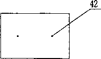
Fig. 4 is the front view of rainfall gauge stop device;
Fig. 5 is the lateral view of rainfall gauge stop device;
Fig. 6 is the vertical view of rainfall gauge stop device.
Fig. 7 is an operating principle block diagram of the present invention.
Fig. 8 is a course of work block diagram of the present invention.
Among the figure: the import of 1-rainwater collection conduit, 2-separation chamber manhole, 3-coarse rack, the thin aperture plate of 5-, 6-separation chamber, 7-pod apertures, 8-demarcation strip, 10-early-stage rainwater collecting chamber, 11-early-stage rainwater collecting chamber manhole, 12-submersible pump, 13-water falling hole, 14-pond body.
4-rainfall gauge stop device, 41-electronic level meter, 42-underflow hole, 43-effluent hole, 44-leg.
9-early-stage rainwater partition apparatus, 91-ball float, the holder of 92-horizontal ball, 93-railing, 94-backing plate, 95-bolt.
(5) specific embodiment
Referring to Fig. 1, initial rain water drainage tank of the present invention is divided into separation chamber 6 and early-stage rainwater collecting chamber 10 two large divisions by a demarcation strip 8 in the pond body 14.The separation chamber be positioned at the early-stage rainwater collecting chamber above, above-mentioned two Room are communicated with separation chamber's manhole 2 and early-stage rainwater collecting chamber manhole 11 upward respectively, manhole is provided with the maintenance cover plate, the lower sidewalls of separation chamber's manhole 2 is communicated with rainwater collection conduit import 1, below with respect to the import of rainwater collection conduit is equipped with coarse rack 3, the base plate of separation chamber, be on the demarcation strip, have at least two water falling holes 13 that communicate with the early-stage rainwater collecting chamber, each water falling hole is connected with an early-stage rainwater partition apparatus 9 respectively, in the separation chamber, have the pod apertures 7 of later stage rainwater above the demarcation strip, thin aperture plate 5 is arranged on it, and be connected to later stage rainwater collecting pit.Smooth and easy for draining, the bottom surface of above-mentioned early-stage rainwater collecting chamber 10 is directed downwards inclination to the manhole of this chamber.Above-mentioned pond body can be steel reinforced concrete pool, glass fiber reinforced plastic pond or masonry and builds the pond by laying bricks or stones.Early-stage rainwater collecting chamber and separation chamber are provided with manhole and maintenance cover plate 2 respectively.Submersible pump 12 in coarse rack 3 in the separation chamber, rainfall gauge stop device 4 and the early-stage rainwater collecting chamber 10 can rise to the ground maintenance at any time.
Referring to Fig. 2, Fig. 3, above-mentioned early-stage rainwater partition apparatus 9 comprise a diameter greater than around the ball float 91 of water falling hole, the water falling hole 13 that the upper end is fixed on demarcation strip, the lower end connect horizontal ball holder 92 and block around ball float four limits four railings 93.Above-mentioned ball float can be styrofoam medicine ball, plastic hollow ball or stainless steel hollow ball.Above-mentioned horizontal ball holder can be horizontal supporting plate, horizontal pressure pin or level holder net.Above-mentioned railing can be solid hopkinson bar or hollow stem.The railing upper and lower end can have screw thread, and its lower end can be by bolt 95 fixed level ball holders, and its upper end can be fastening with the backing plate 94 that is arranged on demarcation strip water falling hole top and bottom by bolt.
The operating principle of early-stage rainwater partition apparatus 9: this device is a ball float abandoned stream partition apparatus, utilize buoyancy of water, when drainage tank is filled with when promptly reaching the abandoned stream volume, ball float with regard on float to position topmost, the water falling hole that rainwater flows into is blocked, thereby realized abandoned stream and collect the partition that flows.In order to guarantee that ball float is not stuck, the strength of enough shutoff water falling holes is arranged simultaneously, adopt large-scale ball-type float, and ball float is limited in the scope that does not have fixed contact, also can move both vertically with being no less than 3 post and rails.Avoid because the deposition of water pollutant and the corrosivity of water are sticked together ball float and post and rail, can not move and lost efficacy with the water surface.For safety and dependable flow more, the abandoned stream partition apparatus more than two covers should be set in each drainage tank inside.
Referring to Fig. 4, Fig. 5, Fig. 6, above-mentioned coarse rack below is provided with rainfall gauge stop device 4, this rainfall gauge stop device is one to put into the pond body of electronic level meter 41 at the bottom of the pond, long 1500 millimeters of this pond body, wide 1000 millimeters, high 700 millimeters, leg 44 is high 200 millimeters, 42, the two underflow holes, underflow hole that have two diameters in the bottom surface and be 30 millimeters are at a distance of 750 millimeters, locate 300 millimeters at every interval to have a diameter be 30 millimeters effluent hole 43 for 100 millimeters at the bottom of the pond body sidewall is apart from the pond.
Rainfall gauge stop device 4 is the basic principle work according to the hydro science orifice outflow.When rainfall stops, also having in the rainwater collection conduit partial discharge constantly to compile, so rainfall stop not represent stopping that rainwater collects.When the rainwater collection conduit has not rained water when flowing, the water tank of this device is a full water, the water tank of this device has the underflow hole and the effluent hole of reservation, by aperture flowing water, with water emptying last in the water tank, the quantity of these apertures and big young pathbreaker determine the emptying time of water in the water tank, thereby obtain certain time delay, electronic level meter in the water tank will provide signal when cistern water level arrives a certain position, prove water tank emptying, and rainwater is collected and stopped.
Referring to Fig. 7, application principle of the present invention: rainwater drops to earlier on ground, the roof, enters the rainwater collection conduit after confluxing, flow into initial rain water drainage tank by the pipeline runoff, enter later stage rainwater collecting pit then, after handling reuse, flow into the rainwater reuse water spot at last.
Referring to Fig. 8, the course of work of the present invention: the principle that adopts volume to separate, will need the part rainfall of abandoned stream to store, again early-stage rainwater and later stage rainwater are separated, the later stage rainwater stores separately.The rainwater of collecting is introduced into the separation chamber, remove bigger impurity through coarse rack, enter the early-stage rainwater collecting chamber by the early-stage rainwater partition apparatus of installing on the demarcation strip, when the water level of initial stage rainwater collecting chamber rises to maximum abandoned stream volume, the early-stage rainwater partition apparatus will be closed the water falling hole on the demarcation strip automatically, and the later stage rainwater will flow to later stage rainwater collecting pit by pod apertures through fine fack.The rainwater of early-stage rainwater collecting chamber misses municipal storm-water drainage peak through the storage of certain hour after rain stops, be discharged to municipal Storm Sewer Network by the submersible pump that is arranged at the bottom of the pond, or replenish nature or landscape water body nearby.
The most suitable relatively large rainwater catchment system system of the present invention, whole early-stage rainwater collecting pit is structure, generally should adopt steel concrete to build.In concrete engineering, the volume of collecting chamber, separation chamber, size and scale and rainfall gauge stop device and abandoned stream partition apparatus scale and number needs will specifically be calculated definite.
Claims (10)
1. initial rain water drainage tank, comprise a pond body that is communicated with the rainwater collection conduit, it is characterized in that: its pond body is divided into separation chamber and early-stage rainwater collecting chamber two large divisions by a demarcation strip, the separation chamber be positioned at the early-stage rainwater collecting chamber above, early-stage rainwater collecting chamber and separation chamber are communicated with manhole upward respectively, manhole is provided with the maintenance cover plate, the sidewall of the manhole below of separation chamber is communicated with the import of rainwater collection conduit, below with respect to the import of rainwater collection conduit is equipped with coarse rack, the base plate of separation chamber, be on the demarcation strip, have at least two water falling holes that communicate with below early-stage rainwater collecting chamber, be connected with an early-stage rainwater partition apparatus respectively below each water falling hole, have the later stage rainwater pod apertures of leading to later stage rainwater collecting pit on demarcation strip, this hole is provided with thin aperture plate.
2. initial rain water drainage tank according to claim 1 is characterized in that: above-mentioned pond body is that steel reinforced concrete pool, glass fiber reinforced plastic pond or masonry are built the pond by laying bricks or stones.
3. initial rain water drainage tank according to claim 2 is characterized in that: above-mentioned early-stage rainwater collecting chamber is built-in with submersible pump.
4. initial rain water drainage tank according to claim 3 is characterized in that: the bottom surface of above-mentioned early-stage rainwater collecting chamber is directed downwards inclination to the manhole of this chamber.
5. according to claim 1 or 2 or 3 or 4 described initial rain water drainage tanks, it is characterized in that: the rainfall gauge stop device is set below coarse rack in the above-mentioned separation chamber, this rainfall gauge stop device is one to put into the pond body of electronic level meter in the pond, this pond body has at least two underflow holes in the bottom surface, have at least two effluent holes in body two sides, pond.
6. initial rain water drainage tank according to claim 5, it is characterized in that: above-mentioned early-stage rainwater partition apparatus be connected in water falling hole on the demarcation strip under, it comprise a diameter greater than the ball float of water falling hole be no less than 3 and vertically block around ball float and and do not have the railing that stationarity contacts with ball float, the air line distance of any two railings is all less than floating ball diameter, the upper end of railing is fixed on the demarcation strip around the water falling hole, and the lower end of railing connects the horizontal ball holder.
, initial rain water drainage tank according to claim 6, it is characterized in that: the ball float of above-mentioned early-stage rainwater partition apparatus is styrofoam medicine ball, plastic hollow ball or stainless steel hollow ball.
8. initial rain water drainage tank according to claim 7 is characterized in that: the horizontal ball holder of above-mentioned early-stage rainwater partition apparatus is horizontal supporting plate, horizontal pressure pin or level holder net.
9. initial rain water drainage tank according to claim 8 is characterized in that: the railing of above-mentioned early-stage rainwater partition apparatus is solid hopkinson bar or hollow stem.
10. initial rain water drainage tank according to claim 9, it is characterized in that: the railing upper and lower end of above-mentioned early-stage rainwater partition apparatus has screw thread, its lower end is by the holder of bolt horizontal ball, and its upper end is fastenedly connected by bolt and the backing plate that is arranged on the water falling hole top and bottom.
Priority Applications (1)
| Application Number | Priority Date | Filing Date | Title |
|---|---|---|---|
| CNB2006102007994A CN100414046C (en) | 2006-08-15 | 2006-08-15 | Initial rain water drainage tank |
Applications Claiming Priority (1)
| Application Number | Priority Date | Filing Date | Title |
|---|---|---|---|
| CNB2006102007994A CN100414046C (en) | 2006-08-15 | 2006-08-15 | Initial rain water drainage tank |
Publications (2)
| Publication Number | Publication Date |
|---|---|
| CN1908326A true CN1908326A (en) | 2007-02-07 |
| CN100414046C CN100414046C (en) | 2008-08-27 |
Family
ID=37699538
Family Applications (1)
| Application Number | Title | Priority Date | Filing Date |
|---|---|---|---|
| CNB2006102007994A Expired - Fee Related CN100414046C (en) | 2006-08-15 | 2006-08-15 | Initial rain water drainage tank |
Country Status (1)
| Country | Link |
|---|---|
| CN (1) | CN100414046C (en) |
Cited By (9)
| Publication number | Priority date | Publication date | Assignee | Title |
|---|---|---|---|---|
| CN101864789A (en) * | 2010-06-08 | 2010-10-20 | 王耀堂 | Volume type rain early-stage split-flow device |
| CN102996892A (en) * | 2012-12-11 | 2013-03-27 | 施建刚 | Time delaying valve |
| CN103195130A (en) * | 2013-03-29 | 2013-07-10 | 中国地质大学(武汉) | Sewage-intercepting and flow-abandoning type rain collector capable of performing back flushing automatically |
| CN103821955A (en) * | 2014-03-24 | 2014-05-28 | 铁道第三勘察设计院集团有限公司 | Air shaft set water-collecting well hydraulic communicating valve device |
| CN103866846A (en) * | 2014-02-21 | 2014-06-18 | 武汉圣禹排水系统有限公司 | Primary rainwater separation method |
| CN104674891A (en) * | 2015-02-09 | 2015-06-03 | 广西威尔森环保科技开发有限公司 | Power-free rainwater recycling system |
| CN107806166A (en) * | 2017-11-08 | 2018-03-16 | 武汉市政工程设计研究院有限责任公司 | It is a kind of that there is the gutter inlet device for shunting function of damming |
| CN110924469A (en) * | 2019-11-11 | 2020-03-27 | 西安重光明宸检测技术有限公司 | Rainwater collecting device for detection |
| CN110954374A (en) * | 2019-11-11 | 2020-04-03 | 西安重光明宸检测技术有限公司 | Rainwater collection device for rainwater detection |
Family Cites Families (5)
| Publication number | Priority date | Publication date | Assignee | Title |
|---|---|---|---|---|
| FR2702235B1 (en) * | 1993-03-05 | 1995-06-09 | Carrieres Foreziennes | RECEIVER OF ELEVATION SANITATION NETWORKS WITH THUNDERSTORM OVERLOAD, OVERLOAD OPENING AND DISCHARGE VALVE. |
| CA2125206C (en) * | 1993-06-07 | 2000-07-25 | Yasuo Yamabe | Vacuum valve control device and vacuum valve |
| CN1162593C (en) * | 2002-12-13 | 2004-08-18 | 北京建筑工程学院 | Flow separation type rainwater autoamtic drainage method and device |
| JP4060248B2 (en) * | 2003-07-15 | 2008-03-12 | 株式会社奥村組 | Underground structure |
| CN2668707Y (en) * | 2004-01-08 | 2005-01-05 | 北京泰宁科创科技有限公司 | Rainwater primary fluid-discarding device |
-
2006
- 2006-08-15 CN CNB2006102007994A patent/CN100414046C/en not_active Expired - Fee Related
Cited By (13)
| Publication number | Priority date | Publication date | Assignee | Title |
|---|---|---|---|---|
| CN101864789A (en) * | 2010-06-08 | 2010-10-20 | 王耀堂 | Volume type rain early-stage split-flow device |
| CN102996892A (en) * | 2012-12-11 | 2013-03-27 | 施建刚 | Time delaying valve |
| CN103195130A (en) * | 2013-03-29 | 2013-07-10 | 中国地质大学(武汉) | Sewage-intercepting and flow-abandoning type rain collector capable of performing back flushing automatically |
| CN103195130B (en) * | 2013-03-29 | 2014-04-09 | 中国地质大学(武汉) | Sewage-intercepting and flow-abandoning type rain collector capable of performing back flushing automatically |
| CN103866846B (en) * | 2014-02-21 | 2015-06-17 | 武汉圣禹排水系统有限公司 | Primary rainwater separation method |
| CN103866846A (en) * | 2014-02-21 | 2014-06-18 | 武汉圣禹排水系统有限公司 | Primary rainwater separation method |
| CN103821955A (en) * | 2014-03-24 | 2014-05-28 | 铁道第三勘察设计院集团有限公司 | Air shaft set water-collecting well hydraulic communicating valve device |
| CN104674891A (en) * | 2015-02-09 | 2015-06-03 | 广西威尔森环保科技开发有限公司 | Power-free rainwater recycling system |
| CN104674891B (en) * | 2015-02-09 | 2017-03-08 | 广西威尔森环保科技开发有限公司 | A kind of unpowered rainwater recycle utilizes system |
| CN107806166A (en) * | 2017-11-08 | 2018-03-16 | 武汉市政工程设计研究院有限责任公司 | It is a kind of that there is the gutter inlet device for shunting function of damming |
| CN107806166B (en) * | 2017-11-08 | 2023-10-20 | 武汉市政工程设计研究院有限责任公司 | Gutter inlet device with flow dividing and intercepting functions |
| CN110924469A (en) * | 2019-11-11 | 2020-03-27 | 西安重光明宸检测技术有限公司 | Rainwater collecting device for detection |
| CN110954374A (en) * | 2019-11-11 | 2020-04-03 | 西安重光明宸检测技术有限公司 | Rainwater collection device for rainwater detection |
Also Published As
| Publication number | Publication date |
|---|---|
| CN100414046C (en) | 2008-08-27 |
Similar Documents
| Publication | Publication Date | Title |
|---|---|---|
| CN100414046C (en) | Initial rain water drainage tank | |
| CN104817209B (en) | Buried efficient early-stage rainwater processing means | |
| CN102102392B (en) | Integrated initial rainwater draining well and method for draining rainwater | |
| CN202017224U (en) | Distributional automatic rainwater flow abandoning device for roof | |
| CN103590484B (en) | Automatic hydraulic control leaping weir initial rainwater catch basin and flow closure method | |
| CN203514395U (en) | Impurity discarding system auto-adaptive to water level variation to extract clean rainwater | |
| CN204530842U (en) | Rain water collecting system | |
| CN104631547A (en) | Rainwater collecting system | |
| CN201506993U (en) | Initial rain split-flow device | |
| CN110984351A (en) | Automatic diverging device of initial stage rainwater | |
| CN202595895U (en) | Float ball lever interception equipment | |
| CN110093968B (en) | Intelligent initial rainwater distribution system | |
| CN105863038B (en) | A kind of early-stage rainwater stream abandoning device | |
| CN201826345U (en) | Tubular rainwater discarding device | |
| CN211817483U (en) | Automatic rainwater shunting and filtering bucket for building | |
| CN207047994U (en) | A kind of Water-quality control shunting well | |
| CN111535416B (en) | Sponge urban rainwater source control system and process based on delay adjustment technology | |
| CN203559482U (en) | Hydraulic automatic control leaping weir initial rainwater intercepting well | |
| CN103774736B (en) | A kind of urban drainage pipe network rainwater shunting process and storage system | |
| KR101325496B1 (en) | Water purified collecting equipment | |
| CN202187414U (en) | Water sealing drainer | |
| CN110670703B (en) | Urban new district initial stage rainwater diverging device and arrange thereof | |
| CN108314137A (en) | A kind of height slot type greasy dirt floating collection system | |
| CN111622331B (en) | Seepage type automatic reset rainwater discarding well | |
| CN114263257A (en) | Rain and sewage diversion system |
Legal Events
| Date | Code | Title | Description |
|---|---|---|---|
| C06 | Publication | ||
| PB01 | Publication | ||
| C10 | Entry into substantive examination | ||
| SE01 | Entry into force of request for substantive examination | ||
| C14 | Grant of patent or utility model | ||
| GR01 | Patent grant | ||
| C17 | Cessation of patent right | ||
| CF01 | Termination of patent right due to non-payment of annual fee |
Granted publication date: 20080827 Termination date: 20110815 |