CN1880161B - Hydraulic disc brake lever assembly - Google Patents
Hydraulic disc brake lever assembly Download PDFInfo
- Publication number
- CN1880161B CN1880161B CN200610092810XA CN200610092810A CN1880161B CN 1880161 B CN1880161 B CN 1880161B CN 200610092810X A CN200610092810X A CN 200610092810XA CN 200610092810 A CN200610092810 A CN 200610092810A CN 1880161 B CN1880161 B CN 1880161B
- Authority
- CN
- China
- Prior art keywords
- main piston
- master cylinder
- bar
- piston
- housing
- Prior art date
- Legal status (The legal status is an assumption and is not a legal conclusion. Google has not performed a legal analysis and makes no representation as to the accuracy of the status listed.)
- Active
Links
Images


Classifications
-
- B—PERFORMING OPERATIONS; TRANSPORTING
- B62—LAND VEHICLES FOR TRAVELLING OTHERWISE THAN ON RAILS
- B62L—BRAKES SPECIALLY ADAPTED FOR CYCLES
- B62L3/00—Brake-actuating mechanisms; Arrangements thereof
- B62L3/02—Brake-actuating mechanisms; Arrangements thereof for control by a hand lever
- B62L3/023—Brake-actuating mechanisms; Arrangements thereof for control by a hand lever acting on fluid pressure systems
Abstract
A brake lever assembly for actuating a hydraulic system is shown and described. The brake lever assembly comprises a housing, a master cylinder disposed in the housing, and a master piston disposed in the master cylinder. The master piston ahs an adjustable dead band. A lever is connected to the housing and has an adjustable reach. The lever is pivotable about a first axis to adjust the reach and is pivotable about a second axis to actuate the master piston.
Description
Related application
The application is the application No.11/061 that submitted on February 18th, 2005,358 part continuation application, and its full content is hereby incorporated by.
Technical field
The present invention relates to hydraulic brake, relate in particular to a kind of hydraulic brake lever assembly that is preferably used for bicycle.
Background technology
In recent years, some High Performance bicycle has the hydraulic brake of being included.The hydraulic disk brake system generally includes caliper housing, the first movable brake lining and the second fixing or movable brake lining.Movable brake lining typically is attached on the piston, and piston can move in response to the fluid pressure that applies by the hydraulic fluid conduit in the caliper housing.Brake lining is positioned on the either side of rotor, and this rotor is attached on the front-wheel or trailing wheel of bicycle.When piston was applied fluid pressure, brake lining and rotor formed and contacts, thereby applied friction drag and cause the bicycle deceleration or stop.
The used hydraulic disk brake system of bicycle is activated by the brake rod that is attached in the bicycle handle bar around common.They also comprise the main piston that is arranged in master cylinder that is activated by brake rod usually.Comprise hydraulic fluid in the master cylinder and keep fluid to be communicated with by fluid circuit and pan brake clamp.Brake lining usually and rotor separate predetermined gap.When bar when handlebar shrinks, main piston moves, and therefore liquid is released master cylinder and pushes in the pipeline that is connected to caliper housing.The motion that fluid enters caliper housing causes that piston moves, and causes that finally brake lining contacts with rotor formation.In case brake lining contacts with rotor, they just provide friction drag, and friction drag can increase by further control lever.In this, caliper housing is fully pressurized, and the further operation of bar has increased system liquid pressure and put on epitrochanterian friction drag.
When operation hydraulic disk brake system, with before rotor formation contacts, can not brake up to brake lining.Therefore, when the cyclist begins to shrink brake rod, can not brake in the meantime, just have one " dead band ".In order to compensate the dead band, the cyclist can at first promptly withdraw brake rod so that make liner contact with rotor, increases friction drag then to desired level more slowly.Therefore, braking and unsmooth.In addition, hydraulic brake system may comprise right-hand rod and the used right-hand rod (perhaps vice versa) of shroud brake caliper that the hub disk brake caliper is used.When left and right side lever was operated simultaneously, preceding brake lining did not contact rotor simultaneously with the back brake lining.In other words, when liner contact rotor, these two bars are also uneven.
In addition, some known system has adjustable dead band.Yet in many these systems, the sphere of action of bar will be subjected to the influence of the change in dead band.On the contrary, some known system comprises adjustable sphere of action feature.Yet, in them many do not allow regulate the dead band, even perhaps they provide the dead band adjusting, but can not under the situation of the sphere of action that does not influence bar, carry out.
Therefore, just need solve the hydraulic brake lever of foregoing problems.
Summary of the invention
According to a first aspect of the invention, provide a kind of master cylinder assembly.Master cylinder assembly comprises master cylinder, and master cylinder has length, top and the bottom that defines axis.First piston places in the master cylinder and can move within it, and second piston places in the master cylinder and can move within it.Master cylinder defines from the top of master cylinder along the threshold distance of axis.First piston preferably defines from the top of master cylinder along the distance of axis.Second piston preferably is operatively connected on primary importance.When the distance on the top from the first piston to the master cylinder was at least threshold distance, second piston preferably can move with respect to first piston.
In a preferred embodiment, when the distance on the top from the first piston to the master cylinder during less than threshold distance, second piston can not move with respect to first piston.In a further advantageous embodiment, first piston has opening, and at least a portion of second piston places opening, and when the distance on the top from the first piston to the master cylinder was at least threshold distance, second piston can move in opening.
According to a further advantageous embodiment of the invention, second piston has the first piston composition surface, first piston has the second piston composition surface, and when the distance on the top from the first piston to the master cylinder during less than threshold distance, the second piston composition surface engages with the first piston composition surface.
According to other preferred embodiment of the present invention, master cylinder comprises the first fluid housing region with fluid egress point, and first piston, second piston and master cylinder define the second fluid containment zone.When the distance on the top from the first piston to the master cylinder during less than threshold distance, the first fluid housing region keeps fluid to be communicated with second fluid containment zone.According to other preferred embodiment of the present invention, when the distance on the top from the first piston to the master cylinder was at least threshold distance, the first fluid housing region did not keep fluid to be communicated with second fluid containment zone basically.
According to another aspect of the present invention, provide master cylinder assembly with top, bottom and length.Master cylinder defines the primary motor area territory along the first of its length.Master cylinder assembly preferably includes to have and places in the master cylinder and the master cylinder assembly of first and second pistons that can move within it.In a preferred embodiment, when the main piston assembly was positioned at the primary motor area territory, first piston can move with second piston, and when the main piston assembly was positioned at overseas of primary motor area at least in part, second piston can move with respect to first piston.
In other preferred embodiment, master cylinder also comprises first lengthwise zone and the second lengthwise zone, the first lengthwise zone is along the second portion with first cross-sectional area of its length, the second lengthwise zone is along the third part with second cross-sectional area of its length, and first cross-sectional area is greater than second cross-sectional area.In another preferred embodiment, first bias unit places between the top and first piston of master cylinder, and wherein first bias unit makes first piston deviate from the top biasing of master cylinder.In a further advantageous embodiment, the shape in the first and second lengthwise zones matches so that limit antelabium.
According to another aspect of the present invention, provide a kind of hydraulic brake lever assembly.This assembly comprises housing and the bar that is connected on the housing.Bar preferably has neutral position, first actuated position and second actuated position with respect to housing.First and second pistons also are in housing and are operatively connected on bar.In a preferred embodiment, bar causes that to the motion of first actuated position first and second pistons move together from neutral position, and bar causes that to the motion of second actuated position second piston moves with respect to first piston from first actuated position.
According to another aspect of the present invention, a kind of master cylinder assembly is provided, and it comprises master cylinder, place first and second pistons of master cylinder and be used for selectively causing that first and second pistons move together in master cylinder and cause the device that first and second pistons relative to each other move.
According to a further aspect of the invention, provide a kind of hydraulic braking lever system.This system comprises bar and the master cylinder assembly with stroke range, and the trip scope comprises first and second zones.Master cylinder assembly has hydraulic fluid and the fluid egress point that is contained in wherein.Bar is operatively connected on master cylinder assembly.In a preferred embodiment, when bar is in the first area, make bar motion certain distance just carry the hydraulic fluid of first volume from outlet, and when bar is in the second area, make bar motion certain distance just carry the hydraulic fluid of second volume, and first volume is greater than second volume from outlet.
According to a further aspect of the invention, provide a kind of brake lever assembly, it comprises housing, being connected in also can be around the bar of pivot axis rotation and the master cylinder assembly that places housing on the housing.Master cylinder assembly preferably includes the main piston that is operatively connected on bar.Pivot axis can be regulated with respect to the optimum seeking site ground of housing, and excellent this ground of master cylinder has adjustable dead band.
In a preferred embodiment, main piston has non-actuated condition and sealing, and master cylinder has port, and when main piston was in non-actuated condition, the dead band was the distance between sealing and the port.In other preferred embodiment, bar has axle and passes the adjustable adaptor union that axle is placed, and has just regulated the dead band with respect to axle mobile adjustable adaptor union.In other preferred embodiment, the position that bar has neutral position and fully activates defines sphere of action between neutral position and abundant actuated position, and this sphere of action scalable.
In other preferred embodiment, master cylinder has longitudinal axis, and pivot axis and longitudinal axis separate.In other preferred embodiment, pivot axis can be regulated along the direction of the longitudinal axis that is arranged essentially parallel to master cylinder with respect to the position of housing.In remaining preferred embodiment, housing also comprises a pair of relative slit, and bar comprises pivot, and pivot has the longitudinal axis that defines pivot axis, and pivot movably places this in the relative slit.
According to another aspect of the present invention, provide a kind of brake lever assembly, the bar that it comprises housing, places the master cylinder of housing and be connected on the housing and have a sphere of action.Master cylinder comprises main piston and preferably has adjustable dead band.Bar preferably can be done pivoted so that the regulating action scope around first pivot axis, and bar preferably can be done pivoted so that activate main piston around second pivot axis.In a preferred embodiment, the adjusting of sphere of action and dead band are irrelevant.In other preferred embodiment, the adjusting in dead band and sphere of action are irrelevant.In other preferred embodiment, bar has first pivot that defines first pivot axis and second pivot that defines second pivot axis, and first pivot and second pivot separate.In other preferred embodiment, second pivot is operatively connected on main piston.
In other preferred embodiment, adjustable adaptor union passes pivot and places and be operatively connected on main piston, has wherein just regulated the dead band with respect to pivot mobile adjustable adaptor union.
According to another aspect of the present invention, provide a kind of brake lever assembly.This assembly comprises housing, bar, place the master cylinder of housing, place main piston, dead band control apparatus and the sphere of action control apparatus of master cylinder.Housing preferably has first and second pairs of relative slits, wherein first and second pairs of apart opening of relative slit.Bar preferably has first pivot that places first pair of relative slit and second pivot that places second pair of relative slit.
Preferably, the dead band control apparatus is operatively connected main piston on second pivot and can regulates so that change the position of main piston with respect to second pivot.The sphere of action control apparatus preferably is connected to housing first pivot and can regulates so that change the position of first pivot in first pair of relative slit.
In a preferred embodiment, the position that bar has neutral position and fully activates defines sphere of action between neutral position and abundant actuated position, just regulated the dead band and regulate the position of first pivot in first pair of relative slit.
According to another aspect of the present invention, provide a kind of method of regulating the sphere of action of brake lever assembly.Brake lever assembly comprises the bar that is operatively connected on master cylinder assembly, and bar has neutral position, and master cylinder assembly has the dead band, and this dead band can be regulated under the situation of the neutral position that does not change bar.This method preferably includes and makes bar do pivoted on every side in the bar zone of aliging with master cylinder assembly basically.In a preferred embodiment, master cylinder assembly has longitudinal axis, and the bar area limiting be substantially perpendicular to the pivot axis of the longitudinal axis of master cylinder assembly.
According to another aspect of the present invention, provide a kind of brake lever assembly, it comprises master cylinder assembly with dead band and the main piston that places master cylinder.The device that is used to regulate the dead band is provided.
According to another aspect of the present invention, provide a kind of brake lever assembly, it comprises the housing with a pair of relative slit, the main piston assembly that places housing and have the master cylinder of port and place master cylinder.The main piston assembly preferably includes has the leak free main piston.Main piston preferably has non-actuated condition, when main piston is in non-actuated condition, defines the distance between sealing and the port.First end of bar preferably can pivotally be connected on the housing.Bar preferably has the transverse member that separates with first end, and transverse member preferably places this to relative slit.In a preferred embodiment, adjustable adaptor union is operatively connected transverse member on the main piston assembly, and can regulate adjustable adaptor union so that change distance.
In other preferred embodiment, adjustable adaptor union engages adjacent to each other with the main piston assembly.In other preferred embodiments, main piston is setovered towards bar.In other preferred embodiment, can make adjustable adaptor union rotation to change the position of adjustable adaptor union with respect to bar.
In other preferred embodiment, brake lever assembly also comprises first coupling member, and wherein adjustable adaptor union has adjustable side and abutting end, and abutting end is connected on first coupling member, and first coupling member engages adjacent to each other with the main piston assembly.
In other preferred embodiment, the main piston assembly also comprises second coupling member that is attached on the main piston, and second coupling member engages adjacent to each other with first coupling member.In other preferred embodiment, main piston is first main piston, and first main piston has the hole, and second main piston places this hole at least in part.In other preferred embodiment, adjustable adaptor union has longitudinal axis, and master cylinder has longitudinal axis, and the longitudinal axis of adjustable adaptor union is arranged essentially parallel to the longitudinal axis of master cylinder.
According to another aspect of the present invention, provide a kind of brake lever assembly, the main piston assembly that this assembly comprises housing, places housing and have the master cylinder of port and place master cylinder.The main piston assembly preferably includes main piston, and main piston preferably has sealing and non-actuated condition.Bar can pivotally be connected on the housing and preferably have the gap of first, second forked partial sum between first, second forked portion is divided.Adjustable adaptor union preferably places this gap and bar is operatively connected on main piston.When main piston was in non-actuated condition, sealing defined certain distance with port, and can regulate adjustable adaptor union to change this distance.
In a preferred embodiment, bar also comprises the transverse member that is connecting the first forked partial sum second forked part, and adjustable adaptor union passes transverse member and places.
The present invention can be applied to all types of devices and be not limited to bicycle.
Description of drawings
By with reference to the accompanying drawings, can more easily understand the present invention, wherein:
Fig. 1 is first transparent view of hydraulic brake lever assembly according to the preferred embodiment of the invention;
Fig. 2 is second transparent view of the hydraulic brake lever assembly of Fig. 1;
The cutaway view of the hydraulic brake lever assembly of Fig. 1 that Fig. 3 cuts open for III-III along the line, its king-rod is in neutral position;
Fig. 4 is the cutaway view of the hydraulic brake lever assembly of Fig. 3, and its king-rod is in first actuated position;
Fig. 5 is the cutaway view of the hydraulic brake lever assembly of Fig. 4, and its king-rod is in second actuated position;
Fig. 6 is the detailed view of the part of Fig. 3;
Fig. 7 is the cutaway view of Fig. 6 of cutting open along the line A-A among Fig. 6; And
Fig. 8 is the cutaway view of Fig. 7 of cutting open along the line B-B among Fig. 6.
Identical label is meant identical parts in these a few width of cloth views.
The specific embodiment
Referring to Fig. 1, the preferred embodiment of bicycle brake bar assembly 10 is described.Brake lever assembly 10 is preferably the hydraulic braking bar assembly that is operatively connected on the hydraulic disk brake system.
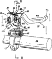
As illustrated in fig. 1 and 2, brake lever assembly 10 preferably is attached in the bicycle handle bar 12 by anchor clamps 13 or other bindiny mechanism that is suitable for.Brake lever assembly 10 generally comprises the housing 14 with first sections 16 and second sections 26, and comprises brake rod 41.
Brake rod 41 is preferably the slender member that comprises far-end 45, and the shape of this far-end is suitable for deviating from handlebar 12 and stretches out.Bar 41 also wraps according to the near-end 47 that is engaging housing 14.In the zone between near-end 45 and far-end 47, a more flat regional 41a is provided, people by bike uses this zone clamping bar 10.Angled transition 41b will be more flat regional 41a be connected on the near-end 47.Preferably angled transition 41b and far-end 45 boths deviate from more flat regional 41a and stretch out so that help to keep cyclist's hand to avoid along the sideway movement of bar 41 length.
See most clearly in Fig. 2, adjustable fastener or set screw 20 are placed in first sections 16 along the direction of the longitudinal axis 104 that is substantially perpendicular to pivot member 22.The upright position that adjustable fastener 20 preferably is configured to allow pivot member 22 changes in to 18 at slit.The head of set screw 20 preferably can be by being arranged in first sections 16 the hole at top enter and be configured to and rotate with respect to housing, and can not advance vertically.This can realize by multiple known devices, for example uses the Belleville packing ring, and it makes the head of set screw 20 setover vertically with respect to housing 14.In order to allow that it moves in the vertical direction pivot member 22, set screw 20 preferably has thread end, and this thread end is more preferably engaging the complementary internal thread hole that is arranged in pivot member 22.Therefore, according to this embodiment, when set screw 20 was rotated, it caused pivot member 22 to move vertically in to 18 at slit.
In Fig. 1 and 2 as can be seen, by the upright position of the pivot member 22 in adjustment housings first sections 16, stroke range (that is, bar 41 is with respect to the range of movement of handlebar 12) that just can adjust bar 41.When pivot member 22 was in the position shown in Fig. 1, bar 41 was just operated in the minimum stroke scope.Yet when pivot member 22 was in slit to 18 bottom, bar 41 was just operated in maximum travel limit.
Preferably, housing 14 comprises that also second sections, 26, the second sections 26 are holding the preferred embodiment (not shown among Fig. 1-2) of master cylinder assembly 30.Identical with first sections 16, second sections 26 comprises a pair of aligned slots 28 (being shown 28a and 28b at Fig. 3-5) that is arranged in housing 14 both sides.The forked portion branch of bar near-end 47 comprise a pair of with spaced apart and with slit to 28 aligned holes that align.These holes and slit are all putting actuation member 38 to 28.Actuation member 38 and slit to 28 and the bar hole engage and just help to remain in bar 41 in the housing 14 and activate the main piston assembly, as described below.In addition, preferably provide fastener 40 so that help actuation member 38 to be connected on the master cylinder 30 as screw or bolt.
Fig. 3-5 shows the cutaway view of the preferred embodiment of brake lever assembly 10 of the present invention.The cutaway view of Fig. 3-5 is cut open along the line III-III among Fig. 1.Three different views of Fig. 3-5 are represented the diverse location of bar 41 with respect to housing 14 and handlebar 12.Fig. 3 represents to be in the bar 41 of neutrality or non-actuated position.Fig. 4 represents to be in the bar 41 of first actuated position, and Fig. 5 represents to be in the bar 41 of second actuated position.
As described below, preferably, bar 41 from neutral position move to first, second actuated position be used to force hydraulic fluid from brake lever assembly 10 to the hydraulic disk brake system.The present invention can use together with multiple different system, and these systems comprise bicycle hydraulic disk brake system, as U.S. Patent No. 6,491, and the system described in 144 (" ' 144 patents "), the full content of this patent is incorporated herein by reference.Yet the present invention is not limited to any specific hydraulic system or hydraulic disk brake system.Therefore, this with reference to the disclosure of ' 144 patents so that the preferred embodiments of the present invention only are shown.As shown in Figure 16 of ' 144 patent, the hydraulic disk brake system generally includes caliper housing and one or more subordinate piston, and these pistons can be in response to the variation campaign by the hydraulic fluid pressure that hydraulic fluid conduit applied in the caliper housing.Equally as shown, the subordinate piston generally includes friction member, as brake lining.
Figure 16 of ' 144 patent shows this hydraulic disk brake system that is used on the bicycle.As shown, in bicycle was used, caliper housing was placed near the bicycle rotor usually, and described rotor is installed on the front-wheel of bicycle or the trailing wheel and therewith rotates.Brake lining be positioned over usually change in both sides.When the needs glancing impact, hydraulic pressure just puts on the subordinate piston and contacts with rotor so that promote friction member.Friction member just makes cycle wheel rotate slower to the friction drag of rotor and finally stops operating.
In a preferred embodiment of the invention, provide a kind of master cylinder assembly 30 that is connected on the bicycle hydraulic disk brake system.Master cylinder assembly 30 preferably is provided for multistage brake, and it more preferably is two-stage or two stage shut.In particularly preferred embodiment, during the F/s of braking, bar 41 is pulled through the first area of its stroke range, so that make master cylinder assembly cause that friction member or brake lining contact with rotor.This first area generally comprises from about 30 percent to about 70 percent of the total kilometrage scope of bar, preferably include from the total kilometrage scope about 40 percent to about 60 percent, and more preferably comprise from about 45 percent to about 55 percent of total kilometrage scope.
In the subordinate phase of braking, bar 41 is pulled through the second area of its stroke range, thereby makes friction member that the recruitment of pressure and friction drag is provided to rotor.
To the preferred embodiment of the master cylinder assembly 30 shown in Fig. 3-5 be described now.The second housing sections 26 comprises and is generally the master cylinder 31 that is defined in the cylindrical space in the housing 14 that it has top 31a and bottom 31b.In changeing other preferred embodiment, master cylinder 31 comprises two longitudinal region L1 and L2, and wherein the diameter in L1 zone and cross-sectional area are greater than the L2 zone.Use two different master cylinders of diameter to be convenient to form two hydraulic fluid housing regions, and then, provide the ability of two-stage braking to obtain clear understanding by following embodiment.
Master cylinder 31 is putting the main piston assembly 33 that comprises the first piston 32 and second piston 34.In a preferred embodiment, first piston 32 preferably is operatively connected on second piston 34 by longitudinal opening, and the part of second piston 34 is positioned in the described opening with one heart.
For bar 41 is operatively connected on main piston assembly 33, preferably provide one or more coupling members.Can use various coupling member configuration and physical dimension, the situation shown in Fig. 3-5 just is preferable case.In the embodiment of Fig. 3-5, convex-concave coupling member 90 is connected in fastener 40 on the concave-concave coupling member 62.Preferably, the size of the concave portion 90a of convex-concave coupling member 90 is suitable for providing and using the flush fit of the fastener 40 of known devices.For example, fastener 40 can have nose 40a, and this nose 40a engages threadably with complementary negative thread on the inside face that is formed at concave portion 90a.In addition, fastener 40 can be connected on the convex-concave coupling member 90 as welding or gummed by other method.
The nose 90b of convex-concave coupling member 90 preferably is connected in the wide bindiny mechanism 66 that is positioned on the concave-concave coupling member 62 by known method of attachment.In a preferred embodiment, nose 90b presses fit in the wide bindiny mechanism 66 on the concave-concave coupling member 62.Yet as described below, in other preferred embodiment, nose 90b engages adjacent to each other with wide bindiny mechanism 66, rather than is rigidly connected on it.
Preferably, concave-concave adaptor union 62 also comprises the narrow connecting bridge 64 of the upper end 71 that is putting second piston 34, preferably narrow connecting bridge 64 for internal thread pattern so that engaging in the complementary threads on the upper end 71 that is formed at second piston 34.Like this, in the preferred embodiment of Fig. 3-5, bar 41 is operatively connected in second piston 34 by actuation member 38, fastener 40, convex-concave coupling member 90 and concave-concave coupling member 62.Therefore, bar 41 just causes the axial motion of second piston 34 along master cylinder 31 around the pivoting action of pivot member 22.
As shown in Fig. 3-5, first fluid housing region 82 is defined in the master cylinder 31 near 31b place, its bottom, when second piston 34 moved owing to the pivoted of bar 41, the fluid in the first fluid housing region 82 passed outlet 83 and enters hydraulic tubing bindiny mechanism 84.Hydraulic tubing bindiny mechanism 84 is preferably designed so that and can be connected on hydraulic tubing such as the flexible pipe that this hydraulic tubing can be connected on the disc brake caliper then.If brake lever assembly 10 be connected in disc brake assembly one of described in Figure 16 of ' 144 patent on, hydraulic fluid enters moving in this hydraulic tubing and just causes fluid to move into pipeline 37 among Figure 16 of fluid circuit (for example: ' 144 patents of caliper housing) in.
As described in more preceding, when brake lever assembly 10 was connected on the hydraulic disk brake assemblies, the present invention preferably was provided for the two-stage braking.In the embodiment of Fig. 1-5, this two-stage braking connects first piston 32 by operation and second piston 34 is realized.
Referring to Fig. 3, first piston 32 general circular in configuration preferably have the opening that extends along its longitudinal axis, more preferably are through hole 51.Preferably, the size of first piston 32 is suitable for tightly fitting in the master cylinder 31 and can also moves with respect to it simultaneously.
In the preferred embodiment of Fig. 3-5, the part of second piston 34 is placed in the through hole 51.Preferably, the size of through hole 51 is suitable for forming tighter cooperating with the outside face of second piston 34, allows the motion in through hole 51 in the following manner of second piston 34 simultaneously.Second piston 34 also passes plain seal member 91 at the top end of first piston 32 and stretches out.Plain seal member 91 is preferably liner and is included in interior so that helping to seal the top of main piston assembly 33 and the master cylinder 31 that is positioned at the outer piston top separates, thereby reduced the possibility that hydraulic fluid will spill from housing 14.As shown in FIG., first piston 32 comprises radially inner side antelabium 39, and plain seal member 91 leans against on this radially inner side seal lip to be protected plain seal member 91 special in place so that help.
Referring again to Fig. 3, the second piston upper flange 68 preferably includes first piston mating surfaces 69.When bar 41 was in the neutral position, first piston mating surfaces 69 nestled up the complementary second piston mating surfaces 59 that is positioned on the outer piston lower flange 55.In addition, preferably, the upper flange 68 of second piston 34 and the diameter of intermediate flange 70 are less than the L1 part of master cylinder 31, and the part of the lower end 73 between flange 68 and 70 is also like this.Relevant difference helps the formation in the second fluid containment zone 86.As shown in Fig. 3-5, second fluid containment zone 86 is for being preferably located in the annular space of first fluid housing region 82 tops.The especially preferred cross-sectional area that is the cross-sectional area area of the longitudinal axis of master cylinder 31 (that is, perpendicular to) in the second fluid containment zone 86 less than first fluid housing region 82.
Preferably, the second fluid containment zone 86 comprises that bias unit such as spring 78 are so that make first piston 32 deviate from master cylinder bottom 31b biasing.As shown in FIG., 2 the vary in diameter from area L 1 to area L of master cylinder has formed the outstanding antelabium 35 of radially inner side.Spring 78 preferably with one heart round second piston 34 in case make an end near antelabium 35 and the other end near first piston lower flange 55.Because housing 14 keeps being fixed with respect to handlebar 12, antelabium 35 keeps being fixed, thereby allows that spring 78 makes first piston 32 deviate from master cylinder bottom 31b biasing.
Preferably, the embodiment of Fig. 3-5 comprises that also bias unit such as spring 60 are so that make first piston 32 deviate from 62 biasings of concave-concave coupling member.Spring 60 is preferably placed with one heart around the negative thread coupling member 62 and second piston 34.In a preferred embodiment, concave-concave coupling member 62 comprises external flange 63.One end of spring 60 is near the bottom surface of external flange 63.As mentioned above, plain seal member 91 is preferably placed with one heart around second piston 34 and is protruded antelabium 39 against the radially inner side of first piston 32.Preferably lay near the zone of plain seal member 91 or the first piston 32 that is adjacent the end of the spring 60 relative with concave-concave coupling member 62.Therefore, spring 60 preferably makes first piston 32 deviate from 62 biasings of concave-concave coupling member.Like this, when bar 41 during towards handlebar 12 motion, actuation member 38 just moves towards the bottom of master cylinder 31b.Because fastener 40 is connected on the actuation member 38, so these two parts move together.Because fastener 40 motions are so convex-concave coupling member 90 and concave-concave coupling member 62 therewith move.Because spring 60 engages with concave-concave coupling member 90 peaceful containment members 91 (or adjacent part of first piston 32), thus when bar 41 from the neutral position of Fig. 3 when first actuated position of Fig. 4 moves, first piston 32 begins to move towards master cylinder bottom 31b.
Preferably housing 14 comprises the hydraulic fluid reservoir 42 that is used to store hydraulic fluid.Two ports preferably are provided, and promptly timing port 44 and compensation port 46 flow between reservoir 42 and master cylinder 31 so that allow hydraulic fluid.See most clearly in Fig. 3-5, first fluid path 87 is connected in reservoir 42 on the second fluid containment zone 86.See most clearly in Fig. 6-8, second fluid passage 88 couples together second fluid containment zone 86 with first fluid housing region 82.Like this, when bar 41 was in the neutral position shown in Fig. 3, timing port 44 just was communicated with first fluid housing region 82 and fluid circuit bindiny mechanism 84 fluids by first fluid path 87, second fluid containment zone, 86 and second fluid passage 88.
If hydraulic brake is connected on the bar assembly 10, when bar 41 was in the neutral position of Fig. 3 or further deviates from handlebar 12, total fluid displacement of hydraulic brake system will comprise the volume of memory device 42 so.Therefore, the pressure at second fluid containment zone and hydraulic fluid conduit 84 places will be lower.Yet, when bar 41 when first actuated position shown in Fig. 4 moves, operation between bar 41 and the first piston 32 connects and just causes first piston 32 and sealing 58 to be moved towards master cylinder bottom 31b.When sealing 58 arrived timing port 44, first fluid path 87 was isolated with timing port 44 and reservoir 42 basically.In this, the total hydraulic efficiency pressure system volume that can be used for activating brake system is reduced, and the pressure of system begins corresponding increase.If the fluid circuit of attached plate disc brake is full of liquid, so further motion will make subordinate piston and attached brake lining towards rotor motion.
As implied above, when bar 41 moved between the neutral position and first actuated position, the first piston 32 and second piston 34 be motion together preferably.For the ease of this motion, spring 60 preferably be chosen to when bar 41 from neutral position when first actuated position moves, the power that spring 60 applies to outer piston 32 is greater than second spring, 78 applied forces.Especially preferred be the spring constant of spring 60 or rigidity greater than spring 78, wherein rigidity or spring constant are determined by relational expression k=F/x, wherein F equals to make the required power of the linear compression distance x of spring.Because spring strength difference, so when bar 41 from the neutral position of Fig. 3 during to first actuated position motion of Fig. 4, the second piston composition surface 59 of first piston flange 55 will engage the first piston composition surface 69 of second piston 32 adjacent to each other, thereby first piston 32 is moved towards master cylinder bottom 31b with second piston 34.Correspondingly, fluid will by by second fluid passage 88 from second fluid containment zone 86 rows to first fluid housing region 82 and by outlet or fluid egress point 83 from first fluid housing region 82 rows to hydraulic fluid conduit bindiny mechanism 84.
Those skilled in the art will be clear, when bar 41 from the neutral position of Fig. 3 during to first actuated position motion of Fig. 4, the volume of the hydraulic fluid that the outlet of master cylinder 31 or fluid egress point 83 are discharged will equal the fluid displacement sum of discharging from first, second fluid containment zone 82 and 86.In a preferred embodiment, when bar 41 from neutral position when first actuated position moves, at least one will be from its position that can not contact rotor to the motion of the position of its contact rotor in the friction member of attached disk braking system or the brake lining.In case especially preferred is that brake lining will just contact with rotor and can not apply tangible pressure to it when arriving first actuated position of Fig. 4.How those skilled in the art will select the size of master cylinder 31, piston 32 and 34, hydraulic tubing 84 and disc brake caliper parts so that obtain a kind of brake rod and brake system by easy to understand, in case when wherein bar 41 arrived first actuated position, brake lining contacted with rotor and can not apply tangible pressure.
As shown in Figure 4, in case when bar 41 arrived first actuated position, first piston 32 will be in from the critical range place of master cylinder top 31a, sealing 80 outlets that will preferably seal second fluid passage 88 herein.The outlet of sealing second fluid passage 88 will make first fluid housing region 82 and second fluid containment zone, 86 substantial barrier.Therefore, the hydraulic fluid that enters or leave the second fluid containment zone 86 can be ignored or not have.Because the fluid displacement in the second fluid containment zone 86 will be fixed basically and hydraulic fluid is incompressible basically as is known because of liquid, so the second piston composition surface 59 of first piston 32 will deviate from the first piston composition surface 69 of second piston 34 and setover towards the top of master cylinder 31 31a.See most clearly in Fig. 5, in this, bar 41 will cause second piston 34 and first piston 32 to separate towards the further motion of handlebar 12, thereby makes second piston 34 towards master cylinder bottom 31b motion, and that first piston 32 keeps basically is static.Like this, effectively define along the primary motor area of the length of master cylinder 31 from the distance of the outlet of top 31a to the second fluid passage 88 of master cylinder 31, when being positioned at primary motor area with convenient primary piston part 33, first piston 32 is with 34 motions of second piston.Yet in case second piston 34 begins to leave primary motor area and is positioned at its when outside at least in part, second piston 34 just moves with respect to first piston 32.
If brake lever assembly 10 is attached on the hydraulic brake, in case brake lining contact rotor, can will be quite little from the liquid capacity that master cylinder 31 is discharged.Because the representative type hydraulic fluid is incompressible basically,, internal piston 34 is added on epitrochanterian system liquid pressure pressure and friction force so will increasing to revolve towards the further motion of master cylinder bottom 31b.Yet, because the compressibi1ity of various factors such as brake lining, the expansion of hydraulic tubing that is generally flexible hose or extension or because system leak, though in brake lining with after rotor contacts, some liquid also will be by from master cylinder 31 discharges.
To be described the preferred embodiment of use now according to the method for the hydraulic brake lever assembly 10 of previous embodiment manufacturing.According to this method, the bicycle that is provided has the rotor that is positioned on its front-wheel or the trailing wheel.Hydraulic disc brake caliper, for example ' clamp of the Figure 16 in 144 patents are attached on the attached wheel of rotor so that make its brake lining be positioned at the both sides of rotor.
According to this method, bicycle has the hydraulic brake lever assembly 10 that is attached on the handlebar 12.At cyclist some some place by bike the time, the cyclist will want bicycle is slowed down or to stop by the brake application device.At that time, the cyclist will clampingc car 12 and also will clamp the bar 41 that is among the flat regional 41a.As described in more preceding, handlebar 12 is preferably configured for limiting the sideway movement of cyclist's hand along bar 41 length.So the cyclist will be with the speed of constant towards handlebar 12 contraction poles 41.Because bar 41 and main piston assembly 33 are operatively connected,, remain in simultaneously in the primary motor area territory that outlet limited by master cylinder top 31a and fluid passage 88 so the first piston 32 and second piston 34 will begin the motion towards the bottom of master cylinder 31 31b.Between this moving period of bar 41, hydraulic fluid will be disposed to the first fluid housing region 82 from the second fluid containment zone 86 and be disposed to the hydraulic tubing bindiny mechanism 84 from first fluid housing region 82.Therefore, hydraulic fluid will begin to fill the hydraulic fluid conduit that is positioned at caliper housing (unless caliper housing pipeline full of liquid).In case be full of hydraulic fluid in these pipelines, pressure will put on the disc type brake subordinate piston, thereby makes them towards rotor motion.In the meantime, can not brake.
Preferably, the cyclist will continue the speed compression link 41 with same constant.When the cyclist continued to do like this, bar 41 will arrive first actuated position (referring to Fig. 4), and first piston 32 preferably will arrive the critical range from master cylinder top 31a at that time.So the outlet that second fluid passage 88 leaves the second fluid containment zone 86 will be preferably sealed in cup-shaped sealing 80.In this, the fluid volumes of being held in the second fluid containment zone 86 will be fixed basically, and therefore, fluid begins to make first piston 32 to setover towards master cylinder top 31a.Therefore, bar 41 will cause when it leaves the primary motor area territory (referring to Fig. 5) of master cylinder 31 towards the further motion of handlebar 12, and second piston 34 leaves first piston 32 and moves towards master cylinder bottom 31b.Yet it is static basically that first piston 32 will keep.In addition, in case when bar 41 arrived its first actuated positions, brake lining will preferably contact with rotor and can not apply tangible pressure to it.First volume V 1 of hydraulic fluid will be discharged between this first moving period of first actuated position from neutral position at bar 41.
Preferably, the cyclist will continue with from neutral position to the identical speed of the used speed of the first actuated position compression link from first actuated position to the second actuated position compression link 41.In this, owing to brake lining contacts with rotor, so system pressure will begin to increase and put on epitrochanterian pressure by brake lining and will increase.Since the second fluid containment zone 86 will with first fluid housing region 82 substantial barrier, so when bar 41 from first actuated position when second actuated position moves, the total volume V2 of the hydraulic fluid of carrying to the disc brake caliper housing from bar assembly 10 will be less than V1.Like this, according to the preferred embodiment of this method, the Fluid Volume of being carried in the second area of Fluid Volume of in the first area of brake rod 41 strokes, being carried greater than stroke.In particularly preferred embodiment, this method will provide two-stage braking, wherein when bar 41 during towards handlebar 12 contractions, will change from the ratio of master cylinder assembly 31 fluid discharged volumes with the throw of lever.Those skilled in the art will be understood that, for bar 41 for the given displacement in the first area of its stroke range, from the hydraulic fluid volume of master cylinder assembly 31 discharging will greater than bar 41 in second area mobile phase with apart from the time hydraulic fluid volume of being discharged.
As described in not long ago, when the cyclist begins contraction pole during not braking as yet, generally exist in the known hydraulic brake assembly in " dead band ".When using in this article, term " dead band " is meant the sealing of main piston when main piston is in deactivated or quiescence and the distance between the hydraulic fluid reservoir mouth.
To as described in the preferred embodiment of Fig. 3, when bar 42 was in the neutral position, the first piston 32 and second piston 34 were in non-actuated condition as not long ago, and timing port 44 is communicated with first fluid housing region 86 and fluid circuit bindiny mechanism 84 fluids.When first piston 32 was in non-actuated condition, the dead band was along the sealing 58 of the longitudinally measurement of master cylinder 31 and the distance between the timing port 44.
According to a preferred embodiment of the invention, master cylinder assembly 30 has adjustable dead band.Adjustable dead band preferably allows user's charging system hydraulic pressure to change (for example variation of the variation of the shape of hydraulic fluid conduit 84 or effective length or attached actuating system) so that keep consistent actuating sensation and operation.
More preferably, the dead band of master cylinder assembly 30 be can regulate and the sphere of action or the neutral position of bar 41 can not be influenced.When using in this article, term " sphere of action " is meant the scope of the neutral position and the stroke between the abundant actuated position of bar 41.
In the preferred embodiment of Fig. 1-8, the user can regulate the dead band by regulating fastener 40.The dead band can generally regulated in about scope of 2.0 to about 3.0mm, preferably in about scope of 2.2 to about 2.8mm, more preferably in about scope of 2.4 to about 2.6mm.Fastener 40 preferably can use conventional instrument such as screwdriver or general utility wrench to regulate.Fastener 40 also be preferably external thread form in case with the through hole 92 that is formed at actuation member 38 in complementary threaded engagement.Owing to have this threads engage, its longitudinally along master cylinder 31 is moved with respect to braking element 38 so rotate fastener 40.
According to this preferred embodiment, with fastener 40 by known method such as threads engage.Welding, gummed or snap fit connect and are fixed on the convex-concave coupling member 90.Preferably, the nose 90b of convex-concave coupling member 90 engaging adjacent to each other on the concave-concave unitor 62 wide end 66 and can be thereon not attached rigidly.For more stable connection is provided, the post, positioning salience or other projection that engage with complimentary aperture in the wide end 66 that is formed at concave-concave coupling member 62 can be included on the nose 90b.
Preferably, convex-concave coupling member 90 engages with concave-concave adaptor union 62 and just allows that convex-concave coupling member 90 is with respect to 62 rotations of concave-concave transom.When the user regulated fastener 40 rotatably, it will move with respect to actuation member 38 along the longitudinally of master cylinder 31.Regulate fastener 40 also make convex-concave coupling member 90 with fastener 40 along the longitudinally rotation of master cylinder 31 with move.In order to be convenient to this axial motion better, the forked near-end 47 of bar 41 preferably size is suitable for putting convex-concave coupling member 90.
In Fig. 3-5, fastener 40 is arranged in transverse member through hole 92 fully.Therefore, the dead band of master cylinder assembly 30 is in minimum.When fastener 40 when first direction rotates, it will and deviate from master cylinder bottom 31b motion with respect to actuation member 38.Convex-concave coupling member 90 also will be with actuation member 38 rotations and motion.When convex-concave coupling member 90 deviated from master cylinder bottom 31b motion, it will begin to leave concave-concave transom 62.Yet spring 60 and 78 bias will make the first piston 32 and second piston 34 deviate from master cylinder bottom 31b motion till the wide end 66 of concave-concave transom 62 is engaging the nose 90b of convex-concave coupling member 90 again adjacent to each other.Therefore, the static or non-actuated condition of first piston will change, thereby makes sealing 58 deviate from the dead band of 44 motions of timing port and increasing master cylinder assembly 30.
If the dead band is not in minimum (being that fastener 40 fully is not arranged in transverse member through hole 92), then can reduce the dead band by the user.In order to reduce the dead band, fastener 40 is preferably along the second direction rotation opposite with above-mentioned first direction.When fastener 40 when second direction is rotated, it will move towards master cylinder bottom 31b with respect to actuation member 38.Therefore, convex-concave coupling member 90 also will move towards bottom 31b.When convex-concave coupling member 90 when bottom 31b moves, this will impel concave-concave transom 62 to move along same direction, thus compression spring 78 and change the non-actuated condition of first piston 32.Therefore, the distance between sealing 58 and the timing port 44 will reduce, thereby reduces the dead band.
Particularly preferably be the dead band that to regulate master cylinder assembly 30 and the sphere of action that can not influence bar.Referring to Fig. 3, bar 41 is in neutral position, and first piston 32 is in non-actuated condition.When bar 41 activated, it finally will arrive the abundant actuated position that can not further activate again.
The abundant actuated position of the design possibility limiting lever 41 of each parts in the brake lever assembly 10.Yet, in order to guarantee can not influence the sphere of action of bar better, so the abundant actuated position of bar 41 preferably is not subjected to the restriction of second piston fluid contact flange 74 near master cylinder bottom 31b to the adjusting in dead band.On the contrary, preferably use the miscellaneous part of brake lever assembly 10 to come the abundant actuated position of limiting lever, as described below.
For example, according to their length, slit 28a and 28b can be used for the abundant actuated position of limiting lever 41.When bar 41 when handlebar 12 shrinks, actuation member 38 will be moved to 28 along slit, till it arrives the bottom of slit 28a and 28b.In this, can not further activate.
In addition, brake lever assembly 10 can be arranged such that bar 41 comes the abundant actuated position of limiting lever near handlebar 12.The size of housing second sections 26 and/or clamp 13 can be suitable for guaranteeing that bar 41 is engaging handlebar 12 adjacent to each other before actuation member 38 arrival slits are to 28 bottom with before second piston, the 34 arrival master cylinder bottom 31b.This configuration also will prevent the variation of sphere of action of the variable effect bar 41 in dead band.
Preferably, brake lever assembly 10 also comprises the sphere of action adjusting.More preferably, sphere of action can be regulated and can not be influenced the dead band.In the preferred embodiment of Fig. 1-8, neutral position that can adjust bar 41 can not influence the dead band with the sphere of action that changes bar.
As previously mentioned, the upright position of the pivot member 22 in housing first sections 16 can be regulated to change the neutral position of bar.In order to regulate neutral position, thus the user rotate adjustable fastener 20 make pivot member 22 slit to 18 in motion.Because spring 60 and 78 bias, when pivot member 22 when slit moves to 18, will make actuation member 38 near slit to 28 top biasing.Therefore, bar 41 will stop until the further adjusting of pivot member 22 around longitudinal axis 102 pivoted of actuation member 38.Because actuation member 38 does not change by this operation to 28 position with respect to slit, so the dead band of master cylinder assembly 30 will can not be subjected to the influence that the sphere of action of bar is regulated substantially.
Preferred embodiment according to Fig. 1-8, the sphere of action of bar 41 is by making bar 41 around bar zone (being the zone between slit 28a and 28b of bar 41) pivoted, and described bar zone is spaced apart with the longitudinal axis of pivot member 22 and align substantially with master cylinder 31.More specifically, bar 41 around longitudinal axis 102 pivoted of actuation member 38 so that the regulating action scope.As shown in Fig. 1-2, particularly preferably be the longitudinal axis 106 that longitudinal axis 102 is arranged essentially parallel to longitudinal axis 104 and is basically perpendicular to master cylinder 31.
This preferred embodiment allows the sphere of action of user's adjust bar 41 and can not influence the dead band of master cylinder assembly 30, otherwise, allow that the user regulates the dead band of master cylinder assembly 30 and can not influence the sphere of action of bar 41.A kind of bar 41 also is provided, its can be around first axle (longitudinal axis 104 of pivot member 22) pivoted so that activate first piston 32 and second along plug 34, and can be around second axis (longitudinal axis 102 of actuation member 38) pivoted so that the sphere of action of adjust bar.
The sphere of action and the dead band adjustment feature of this preferred embodiment have been described in the scope of double-piston master cylinder assembly.Yet, be to be understood that the double-piston configuration does not need to provide sphere of action described herein and dead band adjustment feature.For example, if the first piston 32 and second piston 34 are replaced by single piston, then can remove spring 60.Spring 78 can also be configured to make single plunger backer to setover from master cylinder bottom 31b.In the exemplary embodiment, an end of spring 78 will engage master cylinder bottom 31b and the other end will engage the bottom surface of single piston adjacent to each other.Embodiment is identical with double-piston, and fastener 40 moves so that regulate the dead band with respect to the leak free non-actuated position that actuation member 38 axial motions will cause being formed on the single piston.Therefore, bar 41 will be around longitudinal axis 104 pivoted of pivot member 22 so that activate single piston, and can be around longitudinal axis 102 pivoted of actuation member 38 so that regulate the sphere of action of neutral position and then adjust bar 41.
The foregoing description is an exemplary embodiment of the present invention.Now, under the situation that does not deviate from invention theory disclosed herein, those skilled in the art will use the foregoing description in a large number and depart from these embodiment.Correspondingly, the present invention is limited separately by the scope of following claim.
Claims (14)
1. brake lever assembly comprises:
Housing;
Bar, it is connected on the housing and can rotates around pivot axis, and wherein the position of pivot axis is corresponding to housing, and this adjustable positions; And
Master cylinder assembly, it places housing and comprises the main piston that is operatively connected on bar;
Wherein master cylinder assembly has adjustable dead band;
Its king-rod has axle and passes the adjustable adaptor union that axle is placed, and makes adjustable adaptor union just can regulate the dead band with respect to the axle motion;
Wherein master cylinder has longitudinal axis, and pivot axis and longitudinal axis are spaced apart; And
Wherein can regulate the position of pivot axis along the direction of the longitudinal axis that is arranged essentially parallel to master cylinder with respect to housing.
2. brake lever assembly according to claim 1, wherein main piston has non-actuated condition and sealing, and master cylinder has port, and the dead band is the distance between main piston be in non-actuated condition time sealing and the port.
3. brake lever assembly according to claim 1, its king-rod have neutral position and are limiting neutral position and the abundant abundant actuated position of the sphere of action between the actuated position, and this sphere of action is adjustable.
4. brake lever assembly according to claim 1, its middle shell also comprise a pair of relative slit, and bar comprises pivot, and pivot has the longitudinal axis that defines pivot axis, and pivot places this in the relative slit movingly.
5. brake lever assembly comprises:
Housing with a pair of relative slit;
Place housing and have the master cylinder of port;
Place the main piston assembly of master cylinder, the main piston assembly comprises main piston, and described main piston has sealing, and this main piston also has non-actuated condition, when main piston is in non-actuated condition, defines the distance between sealing and the port;
Bar with first end and transverse member, wherein said first end can pivotally be connected on the housing, and described transverse member separates and places this to relative slit with first end; And
Transverse member is operatively connected adjustable adaptor union on the main piston assembly, wherein can regulates adjustable adaptor union so that change distance.
6. brake lever assembly according to claim 5, wherein adjustable adaptor union engages adjacent to each other with the main piston assembly.
7. brake lever assembly according to claim 5, wherein main piston is setovered towards bar.
8. brake lever assembly according to claim 5 wherein can make adjustable adaptor union rotation to change the position of adjustable adaptor union with respect to bar.
9. brake lever assembly according to claim 5 also comprises first coupling member, and wherein adjustable adaptor union has adjustable side and abutting end, and abutting end is connected on first coupling member, and first coupling member engages adjacent to each other with the main piston assembly.
10. brake lever assembly according to claim 9, wherein the main piston assembly also comprises second coupling member that is attached on the main piston, second coupling member engages adjacent to each other with first coupling member.
11. brake lever assembly according to claim 5, wherein main piston is first main piston, and the main piston assembly also comprises second main piston, and first main piston has the hole, and second main piston places this hole at least in part.
12. brake lever assembly according to claim 5, wherein adjustable adaptor union has longitudinal axis, and master cylinder has longitudinal axis, and the longitudinal axis of adjustable adaptor union is arranged essentially parallel to the longitudinal axis of master cylinder.
13. a brake lever assembly comprises:
Housing;
Place the master cylinder of housing, master cylinder has port;
Place the main piston assembly of master cylinder, the main piston assembly comprises main piston, and main piston has sealing and non-actuated condition;
Can pivotally be connected in the bar on the housing, bar has the gap of first, second forked partial sum between first, second forked portion is divided;
Adjustable adaptor union, it places this gap and bar is operatively connected on main piston;
Wherein when main piston was in non-actuated condition, sealing defined certain distance with port, and can regulate adjustable adaptor union to change this distance.
14. brake lever assembly according to claim 13, its king-rod also comprise the transverse member that is connecting the first forked partial sum second forked part, adjustable adaptor union passes transverse member and places.
Applications Claiming Priority (2)
| Application Number | Priority Date | Filing Date | Title |
|---|---|---|---|
| US11/156501 | 2005-06-17 | ||
| US11/156,501 US7377367B2 (en) | 2005-02-18 | 2005-06-17 | Hydraulic disc brake lever assembly |
Related Child Applications (2)
| Application Number | Title | Priority Date | Filing Date |
|---|---|---|---|
| CN200910173669.XA Division CN101654137B (en) | 2005-06-17 | 2006-06-16 | Hydraulic brake lever assembly |
| CN200910173675.5A Division CN101704396B (en) | 2005-06-17 | 2006-06-16 | Hydraulic disc brake lever assembly |
Publications (2)
| Publication Number | Publication Date |
|---|---|
| CN1880161A CN1880161A (en) | 2006-12-20 |
| CN1880161B true CN1880161B (en) | 2010-04-21 |
Family
ID=36939246
Family Applications (3)
| Application Number | Title | Priority Date | Filing Date |
|---|---|---|---|
| CN200610092810XA Active CN1880161B (en) | 2005-06-17 | 2006-06-16 | Hydraulic disc brake lever assembly |
| CN200910173669.XA Active CN101654137B (en) | 2005-06-17 | 2006-06-16 | Hydraulic brake lever assembly |
| CN200910173675.5A Active CN101704396B (en) | 2005-06-17 | 2006-06-16 | Hydraulic disc brake lever assembly |
Family Applications After (2)
| Application Number | Title | Priority Date | Filing Date |
|---|---|---|---|
| CN200910173669.XA Active CN101654137B (en) | 2005-06-17 | 2006-06-16 | Hydraulic brake lever assembly |
| CN200910173675.5A Active CN101704396B (en) | 2005-06-17 | 2006-06-16 | Hydraulic disc brake lever assembly |
Country Status (6)
| Country | Link |
|---|---|
| US (1) | US7377367B2 (en) |
| EP (5) | EP1733959B1 (en) |
| CN (3) | CN1880161B (en) |
| BR (1) | BRPI0602301A (en) |
| DE (5) | DE602006011450D1 (en) |
| TW (1) | TWI295253B (en) |
Families Citing this family (19)
| Publication number | Priority date | Publication date | Assignee | Title |
|---|---|---|---|---|
| US7308791B2 (en) * | 2005-02-18 | 2007-12-18 | Shimano Inc. | Hydraulic disc brake lever assembly |
| US20080155982A1 (en) * | 2006-12-28 | 2008-07-03 | Jones Christopher S | Hydraulic Brake Master Cylinder |
| US7540147B2 (en) * | 2007-04-10 | 2009-06-02 | Shimano Inc. | Master cylinder lever for a hydraulic brake with dead-band adjustment mechanism |
| US20090152063A1 (en) * | 2007-12-13 | 2009-06-18 | Szu-Fang Tsai | Pumping device for a hydraulic brake of a bicycle |
| ITMI20080346A1 (en) | 2008-02-29 | 2009-09-01 | Braking Sunstar S P A | "BRAKING DEVICE" |
| TW201031568A (en) * | 2009-02-27 | 2010-09-01 | yuan-hong Wen | Labor-efficient brake lever of bike |
| IT1401076B1 (en) * | 2010-06-09 | 2013-07-12 | Formula Srl | DEVICE FOR ADJUSTING THE VACUUM STROKE IN HYDRAULIC ACTUATORS OF BICYCLES AND MOTORCYCLES. |
| US8615994B2 (en) * | 2010-08-23 | 2013-12-31 | Ryan Lind | Adjustable hydraulic master cylinder assemblies |
| US9096288B2 (en) * | 2012-01-05 | 2015-08-04 | Shimano, Inc. | Dual hydraulic controller for bicycle components |
| US8714322B2 (en) * | 2012-01-16 | 2014-05-06 | Sram, Llc | Hydraulic brake mechanism |
| ITMI20131933A1 (en) | 2013-11-20 | 2015-05-21 | Campagnolo Srl | INTEGRATED CONTROL FOR A BICYCLE HANDLEBAR |
| US10183723B2 (en) * | 2015-03-12 | 2019-01-22 | Sram, Llc | Bicycle control device |
| NO341940B1 (en) * | 2016-03-01 | 2018-02-26 | Ca Tech Systems As | Sequential gear shifter |
| JP7122081B2 (en) * | 2016-09-08 | 2022-08-19 | 株式会社シマノ | Double bearing reel |
| US10710671B2 (en) * | 2017-01-13 | 2020-07-14 | Earth Punched, LLC | Handlebar controls |
| CN114502436A (en) * | 2019-09-27 | 2022-05-13 | 北极星工业有限公司 | Master cylinder for a brake system |
| WO2022220826A1 (en) * | 2021-04-14 | 2022-10-20 | Ox-Motorcycle Products, LLC | Adjustable hydraulic motorcycle brake system and device |
| DE102021123809B4 (en) | 2021-09-15 | 2023-03-30 | Schaeffler Technologies AG & Co. KG | Actuating device for manually actuating a braking device, a vehicle and a vehicle with the actuating device |
| TWI804182B (en) * | 2022-01-27 | 2023-06-01 | 傳誠技研有限公司 | Variable oil hydraulic brake structure |
Family Cites Families (49)
| Publication number | Priority date | Publication date | Assignee | Title |
|---|---|---|---|---|
| JPS502212A (en) * | 1973-05-12 | 1975-01-10 | ||
| JPS57186563A (en) * | 1981-05-13 | 1982-11-17 | Honda Motor Co Ltd | Interlocking brake device for motorcycle |
| DE3216885C2 (en) | 1982-05-06 | 1986-03-13 | Gustav Magenwirth Gmbh & Co, 7432 Urach | Brake cylinder housing for a closed hydraulic system to be attached to the handlebars of a two-wheeled vehicle |
| JPS5940021A (en) | 1982-08-31 | 1984-03-05 | Honda Motor Co Ltd | Device for operating clutch master cylinder |
| US4560049A (en) * | 1982-09-28 | 1985-12-24 | Honda Giken Kogyo Kabushiki Kaisha | Operation device for clutch master cylinder with means to adjust the play stroke of the clutch lever |
| GB8421830D0 (en) * | 1984-08-29 | 1984-10-03 | Automotive Prod Plc | Hydraulic master cylinder |
| JPH0777877B2 (en) * | 1985-12-06 | 1995-08-23 | 本田技研工業株式会社 | Adjustable operating lever for vehicle |
| GB8617729D0 (en) | 1986-07-19 | 1986-08-28 | Sp Tyres Uk Ltd | Vehicle wheels |
| JPS6328700A (en) | 1986-07-22 | 1988-02-06 | ワイケイケイ株式会社 | Manufacture of decorative body |
| KR900008424B1 (en) * | 1987-06-05 | 1990-11-20 | 닛신 고오교오 가부시끼가이샤 | Lever system for vehicles |
| JPH01237282A (en) | 1988-03-18 | 1989-09-21 | Suzuki Motor Co Ltd | Operating lever device for motorcycle and the like |
| IT218037Z2 (en) * | 1988-12-12 | 1992-03-30 | Brembo Spa | POSITION REGULATOR FOR MANUAL CONTROL LEVERS, APPLIED TO HANDLEBARS |
| JPH0331054A (en) | 1989-06-27 | 1991-02-08 | Nissin Kogyo Kk | Operational lever for fluid pressure master cylinder for vehicle |
| JPH041034Y2 (en) * | 1989-09-13 | 1992-01-14 | Nissin Kogyo Kk | |
| GB2236819B (en) | 1989-09-14 | 1993-07-14 | Gen Motors France | Dual master cylinder |
| JPH0632275A (en) | 1992-07-15 | 1994-02-08 | Nissin Kogyo Kk | Master cylinder |
| GB9305838D0 (en) | 1993-03-20 | 1993-05-05 | Automotive Products Plc | An operating mechanism for a hydraulic master cylinder |
| JP3393311B2 (en) | 1993-12-27 | 2003-04-07 | 日信工業株式会社 | Hydraulic master cylinder device for vehicles |
| JPH08114244A (en) | 1994-10-14 | 1996-05-07 | Nissin Kogyo Kk | Hydraulic master cylinder device for bar handle vehicle |
| JPH08268369A (en) | 1995-03-30 | 1996-10-15 | Nissin Kogyo Kk | Liquid-pressure master cylinder operation lever for bar-handle vehicle |
| CA2163475A1 (en) * | 1995-11-22 | 1997-05-23 | Joseph Debreczeni | Hydraulic brake system |
| GB9604170D0 (en) | 1996-02-28 | 1996-05-01 | Weatherhill Ian | Hydraulic brakes |
| US5813501A (en) * | 1996-10-18 | 1998-09-29 | Terry, Sr.; Maurice C. | Hand operated hydraulic vehicle brake |
| JP3731835B2 (en) | 1996-11-06 | 2006-01-05 | 本田技研工業株式会社 | Hydraulic operating lever device |
| GB2321682B (en) | 1997-02-01 | 2001-02-14 | Automotive Products Plc | A braking system |
| JPH10230886A (en) | 1997-02-20 | 1998-09-02 | Nissin Kogyo Kk | Operation lever of hydraulic master cylinder for bar handle vehicle |
| IT237821Y1 (en) | 1997-07-23 | 2000-09-29 | Crc Ct Ricerche Cagiva S A | PUMP ASSEMBLY, FRONT BRAKE SYSTEM LIQUID TANK AND BRAKE OR CLUTCH LEVER FOR A MOTORCYCLE |
| US5950772A (en) | 1997-08-29 | 1999-09-14 | Hayes Brake, Inc. | Bicycle brake system having a flexible disk |
| EP0991554A1 (en) | 1998-04-28 | 2000-04-12 | Rockshox, Inc. | Concentric compensator chamber and master cylinder for disc brake system |
| US6119821A (en) * | 1998-12-23 | 2000-09-19 | Giant Manufacturing Co., Ltd. | Hydraulic compensation device for compensating a positional deviation of a brake pad |
| JP4357660B2 (en) * | 1999-08-27 | 2009-11-04 | 本田技研工業株式会社 | Master cylinder device for vehicle |
| JP4249868B2 (en) * | 1999-12-16 | 2009-04-08 | 日信工業株式会社 | Bar handle vehicle operating lever grip allowance adjustment mechanism |
| DE10017199A1 (en) * | 2000-04-06 | 2001-10-11 | Magenwirth Gmbh Co Gustav | Brake actuator unit for hydraulic brakes of two-wheeled vehicles has brake lever with pivot axis formed by axis of plastic bearing stud, and moveable parallel to central brake cylinder axis |
| DE10017198A1 (en) * | 2000-04-06 | 2001-10-11 | Magenwirth Gmbh Co Gustav | Brake actuator unit for hydraulic brakes of two-wheeled vehicles has piston guided with one end in brake cylinder with other end in handlebar-mounted housing |
| EP1160152B1 (en) | 2000-06-02 | 2005-12-07 | Freni Brembo S.p.A. | Device for adjusting the position of the operating lever of a hydraulic actuator |
| US6336525B1 (en) * | 2000-06-19 | 2002-01-08 | Tony Leng | Disc brake oil pressure adjusting device for bikes |
| US6401882B1 (en) * | 2000-06-30 | 2002-06-11 | Shimano Inc. | Heat insulator for disc brake |
| JP4374127B2 (en) | 2000-08-31 | 2009-12-02 | 日信工業株式会社 | Bar handle vehicle control lever |
| DE20018705U1 (en) * | 2000-11-02 | 2000-12-28 | Magenwirth Gmbh Co Gustav | Control valve for actuating the brake or clutch of a vehicle with a handlebar |
| JP2002211473A (en) | 2001-01-22 | 2002-07-31 | Nissin Kogyo Co Ltd | Hydraulic master cylinder device for bar handle vehicle |
| ATE271485T1 (en) | 2001-03-02 | 2004-08-15 | Freni Brembo Spa | MASTER CYLINDER FOR A MOTORCYCLE/BICYCLE OR SIMILAR, BRAKE OR CLUTCH |
| US6527303B2 (en) * | 2001-06-04 | 2003-03-04 | Shimano Inc. | Hydraulic hose assembly for bicycle |
| US7204350B2 (en) * | 2001-12-28 | 2007-04-17 | Sram Corporation | Master cylinder lever for a hydraulic disc brake having favorable handle pivot geometry |
| US6804961B2 (en) * | 2001-12-28 | 2004-10-19 | Sram Corporation | Master cylinder lever for a hydraulic disk brake having on the fly dead-band adjustment |
| US20030121736A1 (en) * | 2001-12-28 | 2003-07-03 | Avid, L.L.C. | Master cylinder lever for a hydraulic disc brake having a backpack reservoir |
| ITFI20030242A1 (en) | 2003-09-15 | 2005-03-16 | Formula Srl | DEVICE FOR THE CONTROL OF HYDRAULIC BRAKES IN CYCLES, |
| ITFI20030241A1 (en) * | 2003-09-15 | 2005-03-16 | Formula Srl | DEVICE FOR THE CONTROL OF HYDRAULIC BRAKES IN CYCLES, |
| US6883647B1 (en) * | 2003-09-16 | 2005-04-26 | Chun Te Wen | Hydraulic brake lever for a bicycle |
| ITFI20030265A1 (en) | 2003-10-21 | 2005-04-22 | Formula Srl | DEVICE FOR THE COMMAND OF A HYDRAULIC CLUTCH CIRCUIT. |
-
2005
- 2005-06-17 US US11/156,501 patent/US7377367B2/en active Active
-
2006
- 2006-03-14 TW TW095108613A patent/TWI295253B/en active
- 2006-06-12 DE DE602006011450T patent/DE602006011450D1/en active Active
- 2006-06-12 DE DE602006002318T patent/DE602006002318D1/en active Active
- 2006-06-12 EP EP06012068A patent/EP1733959B1/en active Active
- 2006-06-12 DE DE602006008762T patent/DE602006008762D1/en active Active
- 2006-06-12 DE DE602006013805T patent/DE602006013805D1/en active Active
- 2006-06-12 EP EP07018649A patent/EP1870325B1/en active Active
- 2006-06-12 EP EP07018650A patent/EP1870326B1/en active Active
- 2006-06-12 EP EP07018652A patent/EP1870328B1/en active Active
- 2006-06-12 EP EP07018651A patent/EP1870327B1/en active Active
- 2006-06-12 DE DE602006016757T patent/DE602006016757D1/en active Active
- 2006-06-16 CN CN200610092810XA patent/CN1880161B/en active Active
- 2006-06-16 CN CN200910173669.XA patent/CN101654137B/en active Active
- 2006-06-16 BR BRPI0602301-0A patent/BRPI0602301A/en not_active Application Discontinuation
- 2006-06-16 CN CN200910173675.5A patent/CN101704396B/en active Active
Also Published As
| Publication number | Publication date |
|---|---|
| EP1870326B1 (en) | 2010-04-21 |
| EP1733959A3 (en) | 2007-06-13 |
| US7377367B2 (en) | 2008-05-27 |
| EP1870326A3 (en) | 2008-09-03 |
| EP1870326A2 (en) | 2007-12-26 |
| CN101654137B (en) | 2013-01-02 |
| DE602006011450D1 (en) | 2010-02-11 |
| CN101704396A (en) | 2010-05-12 |
| CN101704396B (en) | 2013-01-02 |
| DE602006013805D1 (en) | 2010-06-02 |
| US20060185943A1 (en) | 2006-08-24 |
| CN1880161A (en) | 2006-12-20 |
| EP1733959B1 (en) | 2008-08-20 |
| EP1733959A2 (en) | 2006-12-20 |
| EP1870325A2 (en) | 2007-12-26 |
| DE602006008762D1 (en) | 2009-10-08 |
| TWI295253B (en) | 2008-04-01 |
| EP1870325A3 (en) | 2008-09-03 |
| EP1870328A3 (en) | 2008-07-09 |
| EP1870327A2 (en) | 2007-12-26 |
| DE602006002318D1 (en) | 2008-10-02 |
| EP1870327A3 (en) | 2008-07-16 |
| EP1870328B1 (en) | 2009-08-26 |
| EP1870328A2 (en) | 2007-12-26 |
| TW200700280A (en) | 2007-01-01 |
| CN101654137A (en) | 2010-02-24 |
| EP1870325B1 (en) | 2010-09-08 |
| DE602006016757D1 (en) | 2010-10-21 |
| EP1870327B1 (en) | 2009-12-30 |
| BRPI0602301A (en) | 2007-02-21 |
Similar Documents
| Publication | Publication Date | Title |
|---|---|---|
| CN1880161B (en) | Hydraulic disc brake lever assembly | |
| CN100519321C (en) | Master cylinder assembly, hydraulic brake lever system and hydraulic disc brake lever assembly | |
| CN101285510B (en) | Master cylinder lever for a hydraulic brake with dead-band adjustment mechanism | |
| US9057395B2 (en) | One piece hydraulic disc brake caliper with one way plumbing | |
| CN100548763C (en) | Interlocking brake system for bar-handle vehicle | |
| WO1999010225A3 (en) | Bicycle brake system | |
| CN103085927B (en) | hydraulic rim brake | |
| CN1868803B (en) | Dual lever hydraulic brake assembly and method of using the same | |
| EP0875443A2 (en) | Hydraulic mechanism housed within a tubular element such as a motorcycle handlebar | |
| SE455590B (en) | MANUAL DEVICE FOR A HYDRAULIC BRAKE SYSTEM WITH SLIR CONTROL WHICH IN THE MAIN CYLINDER HAS A TWO-PISTON PISTON WHICH IS SLIDELY STEERED IN A POSITIONING HOUSING | |
| CN102341293B (en) | Method of relieving power steering assist and power steering system utilizing method | |
| JPH07507519A (en) | Master Cylinder | |
| US11492069B2 (en) | Brake lever assembly for hydraulic brake system | |
| CN101332831A (en) | Fork-truck steering and balancing device | |
| GB1590861A (en) | Hydraulic actuators | |
| GB2420380A (en) | Twin piston gas filled hydraulic actuator | |
| GB2599941A (en) | Brake lever assembly for hydraulic brake system | |
| SU1131711A2 (en) | Master cylinder for hydrostatic system of vehicle | |
| JPH03503872A (en) | Pressure-balanced proportional valve with vent-controlled bypass | |
| SU1078150A1 (en) | Pneumatic drive | |
| KR970027914A (en) | Hydraulic valve of the parking brake system |
Legal Events
| Date | Code | Title | Description |
|---|---|---|---|
| C06 | Publication | ||
| PB01 | Publication | ||
| C10 | Entry into substantive examination | ||
| SE01 | Entry into force of request for substantive examination | ||
| C14 | Grant of patent or utility model | ||
| GR01 | Patent grant |