CN1527930A - Barrel assembly with tubular projectiles for firearms - Google Patents
Barrel assembly with tubular projectiles for firearms Download PDFInfo
- Publication number
- CN1527930A CN1527930A CNA028141415A CN02814141A CN1527930A CN 1527930 A CN1527930 A CN 1527930A CN A028141415 A CNA028141415 A CN A028141415A CN 02814141 A CN02814141 A CN 02814141A CN 1527930 A CN1527930 A CN 1527930A
- Authority
- CN
- China
- Prior art keywords
- projectile
- barrel
- adjacent
- gun barrel
- feature
- Prior art date
- Legal status (The legal status is an assumption and is not a legal conclusion. Google has not performed a legal analysis and makes no representation as to the accuracy of the status listed.)
- Pending
Links
Images


Classifications
-
- F—MECHANICAL ENGINEERING; LIGHTING; HEATING; WEAPONS; BLASTING
- F42—AMMUNITION; BLASTING
- F42B—EXPLOSIVE CHARGES, e.g. FOR BLASTING, FIREWORKS, AMMUNITION
- F42B30/00—Projectiles or missiles, not otherwise provided for, characterised by the ammunition class or type, e.g. by the launching apparatus or weapon used
- F42B30/02—Bullets
-
- F—MECHANICAL ENGINEERING; LIGHTING; HEATING; WEAPONS; BLASTING
- F42—AMMUNITION; BLASTING
- F42B—EXPLOSIVE CHARGES, e.g. FOR BLASTING, FIREWORKS, AMMUNITION
- F42B5/00—Cartridge ammunition, e.g. separately-loaded propellant charges
- F42B5/02—Cartridges, i.e. cases with charge and missile
- F42B5/03—Cartridges, i.e. cases with charge and missile containing more than one missile
-
- F—MECHANICAL ENGINEERING; LIGHTING; HEATING; WEAPONS; BLASTING
- F42—AMMUNITION; BLASTING
- F42B—EXPLOSIVE CHARGES, e.g. FOR BLASTING, FIREWORKS, AMMUNITION
- F42B10/00—Means for influencing, e.g. improving, the aerodynamic properties of projectiles or missiles; Arrangements on projectiles or missiles for stabilising, steering, range-reducing, range-increasing or fall-retarding
- F42B10/32—Range-reducing or range-increasing arrangements; Fall-retarding means
- F42B10/34—Tubular projectiles
-
- F—MECHANICAL ENGINEERING; LIGHTING; HEATING; WEAPONS; BLASTING
- F42—AMMUNITION; BLASTING
- F42B—EXPLOSIVE CHARGES, e.g. FOR BLASTING, FIREWORKS, AMMUNITION
- F42B5/00—Cartridge ammunition, e.g. separately-loaded propellant charges
- F42B5/02—Cartridges, i.e. cases with charge and missile
- F42B5/03—Cartridges, i.e. cases with charge and missile containing more than one missile
- F42B5/035—Cartridges, i.e. cases with charge and missile containing more than one missile the cartridge or barrel assembly having a plurality of axially stacked projectiles each having a separate propellant charge
Abstract
A barrel assembly (10) for munitions and firearms, said barrel assembly including a barrel (12) having a muzzle with a plurality of tubular rounds (11) stacked axially within the barrel together with discrete selectively ignitable propellant charges (15). The rounds (11) suitably include tubular bodies (13a, 13b, 13c, 13d) and closure means (14a, 14b, 14c, 14d) interposed between the tubular rounds for effecting both an operative barrel closure between the tubular rounds (11) and operative sealing engagement with the barrel (12). The propellant charges (15) are contained within each round (11) and selectively ignitable (15a) for propelling an adjacent leading round (13a) and associated closure means (14a) through the muzzle of the barrel.
Description
Technical field
The present invention relates to munitions and firearms.The present invention relates to a kind of barrel assembly that is applicable to of special but non-special use, this barrel assembly has many many projectiles that overlap vertically in the gun barrel, also have the propellant charge that the alternative of many separation is lighted simultaneously, be used for the muzzle that order penetrates projectile gun barrel.This barrel assembly is referred to as " the above-mentioned type " gun barrel later on.
Background technology
The present invention relates to the barrel assembly of munitions and firearms, be specifically related to the barrel assembly of the above-mentioned type, as the inventor described in the international patent application No.PCT/AU94/00124 and PCT/AU96/00459 early.
In some limited application, the for example ultrasonic projectile of known tubular projectile, but the inventor does not also see any alternative overlapping together tubular projectile of lighting that is placed in the gun barrel of propellant charge of companion that is suitable for, specifically be not have a kind of tubular projectile to be suitable for the barrel assembly of the above-mentioned type.
Brief summary of the invention
For electronically controlled munitions and firearms, be sought after providing the barrel assembly that is suitable for launching tubular projectile of a kind of barrel assembly, particularly the above-mentioned type, and a kind of tubular projectile is provided for this reason.
According on the one hand, the invention provides a kind of barrel assembly of the above-mentioned type, this barrel assembly comprises:
Gun barrel with muzzle;
Many tubular projectiles, these projectiles overlay in the gun barrel along axis, and are assembled into can seal with this gun barrel in operation and contact;
Sealing device is configured between the tubular projectile, is used for being implemented in operation the gun barrel sealing between the tubular projectile;
The propellant charge that alternative is lighted, this powder charge is contained in each projectile, and can light, so that launch adjacent front projectile and relevant sealing device by the muzzle of gun barrel.
Tubular projectile preferably stacks in the mode of butt joint, though these projectiles may separate certain distance by propellant charge.Each projectile preferably also comprises the tube-shaped main body with sealing device, and the sealing device is incorporated into the rear portion of projectile at least.
The sealing device also plays a part close rear projectile front end.Perhaps, can use independent sealing device,, make combustion forward projectiles can be penetrated gun barrel as long as after the locking device of front end is being lighted powder charge, make inoperatively for the glue end and the rear end of each projectile.
Locking device can become from tube-shaped main body dishes out, and perhaps can be fixed on the anterior tube-shaped main body.This tubular projectile can be shaped, and makes it have aerodynamic shape, and reaches the flight characteristics that needs.The shape of tube-shaped main body inner surface can keep the axial collimation with flight path when abandoning the sealing device coupling.Perhaps can make the tube-shaped main body imbalance, make an end heavier than the other end.
Locking device is a kind of wall packaged unit, is clipped between the adjacent tube-shaped main body part.Each wall packaged unit can reach gun barrel, contacts and form sealing with gun barrel.Perhaps tubular projectile can have the complementary outer end wall part of docking each other or being adjacent to each other, and the packaged unit of wall is clipped between the inner end wall part.
In preceding a kind of mode, the wall seal member can be clipped between the end face of adjacent tubular projectile.Deformation takes place in the shape of wall seal member under operating condition.Perhaps, can form the outer peripheral portion of wall seal member, make under the axial compressive force effect of end surfaces effect, this outer peripheral portion outwards expands between adjacent tubular projectile, reaches with the gun barrel sealing to contact.For low pressure applications, should not adopt this deformation to make this outer peripheral portion and gun barrel form secure seal and contact.
The end face of adjacent tubular projectile can radially extend along gun barrel, and perhaps, the end face of adjacent tubular projectile can form with complementary wedge-shaped surface on the wall seal member outer peripheral portion that is clipped in the middle and contact.
The tube-shaped main body of adjacent projectile can overlap each other, and forms telescopic combination thus between adjacent projectile.For this reason, projectile comprises the outer end wall part, and this outer end wall is partly entangled the inner end wall part of adjacent projectile, clips the wall seal member between the complementary inner end wall surface of telescopic projectile.
If desired, the sleeve part of adjacent projectile comprises thin-walled portion, and this thin-walled portion can outwards expand, and partly forms sealing with adjacent sleeve projectile and contacts, thereby prevent that powder charge from draining in the gun barrel, perhaps leaks into adjacent powder charge.Perhaps, outwards expansion can be the outer sleeve part, can strengthen the projectile just launched and the sealing of gun barrel thus and contact.
The wall seal that each is clipped in the middle can also become the pressure that makes powder charge and react on its front surface, makes the end surfaces of itself and rear portion projectile form sealing, thereby prevents that powder charge is fired by location of leak in the projectile of adjacent rear portion.This reaction seals between the butt end surface portion that can also occur in projectile and/or occurs between forward projectiles and the wall seal member.
Lighting of propellant charge illustrates in my international patent application early.For this purpose, the propellant charge that each alternative is lighted comprises electrically excited initiator, and this initiator is connected in a pair of annular contact that separates, and this contact extends around projectile, and contact extends through gun barrel and the respective electrical contact that is connected with electronic-controlled installation.
Locking device can form one with projectile, comprise can be movable wall part or the wall of expansion, this wall part can move forward to open mode from sealing state, reaches the state of fitting with gun barrel basically.In the time of in off position, this wall part can to anterior powder charge light the formation reaction, thereby keep or strengthen the sealing effectiveness of sealing device.
Be encased in before the gun barrel, earlier each projectile is loaded onto propellant charge, but if desired, can be encased in seal in the gun barrel in proper order with projectile tube-shaped main body, propellant charge and openend of open front, perhaps as independent operation, perhaps as the result who next projectile tubular body is put into its allocation position.
In another aspect, the invention provides a kind of projectile that penetrates from munitions or firearms gun barrel, above-mentioned projectile comprises:
Open-ended tube-shaped main body, this tube-shaped main body are suitable for being contained in the gun barrel of barrel assembly, and contact with this gun barrel formation sealing in operation;
The wall seal member is suitable for being placed between the tube-shaped main body of above-mentioned tube-shaped main body and adjacent projectile, is used in the gun barrel sealing that realizes in the operation between the projectile;
The propellant charge that alternative is lighted, this powder charge are contained in the tube-shaped main body of adjacent projectile, and this powder charge can be lighted, thereby the tube-shaped main body of above-mentioned projectile can be penetrated the gun barrel mouth.
Brief description of drawings
In order more to understand and to implement the present invention, below with reference to accompanying drawing, this accompanying drawing illustrates exemplary embodiments of the present invention, and these accompanying drawings are:
Figure 1A-1D is a schematic section, and a kind of form of the present invention and its operator scheme are shown;
Fig. 2 A-2D is a schematic cross section, and another embodiment of the present invention and its operator scheme are shown;
Fig. 3 is a perspective view, and a projectile of Fig. 2 A-2D illustrated embodiment is shown;
Fig. 4 is a schematic section, and another kind of form of the present invention is shown;
Fig. 5 is a schematic cross section, and another form of the present invention is shown.
The explanation of preferred embodiment
Among the embodiment shown in Figure 1A-1D, barrel assembly 10 has many projectiles 11, these projectiles are placed in the gun barrel 12 with docking mode vertically, and be suitable for electricity consumption emission or sequential transmission, as described in inventor's international patent application early, perhaps as described in the alternate manner known in this technology.
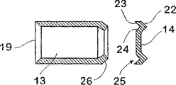
Each projectile 11 comprises tube-shaped main body 13, this main body 13 combines with gun barrel seal 14, the sealing part is configured between adjacent tube-shaped main body 13a, 13b, 13c and the 13d separately, and these tube-shaped main bodies are separated from each other, and propellant charge 15 is contained in the back of seal 14.For example propellant charge 15a is contained among the tube-shaped main body 13b at rear portion, between corresponding gun barrel closure member 14a and 14b.In this embodiment, other propellant charge 15d is contained in the rear portion extension 16 of barrel assembly 10, is used to launch last tube-shaped main body 13d.
From Figure 1A as can be seen, the forward annular end of each main body 13 18 inwardly and extend back forms part circular cone end face 19.This part circular cone end face matches with the complementary portion conical surface 22 that forms on the rear portion outer peripheral portion of gun barrel seal member 14, shown in Figure 1B.Form another complementary portion circular cone front surface 23 around seal 14 outward flanges, shown in Fig. 1 C.This another complementary portion circular cone front surface 23 combines with surface 24 and forms groove 25, and this groove can receive the aft bulkhead 26 of the shape complementarity of each tube-shaped main body 13.
As can be seen, end wall 26 slopes inwardly, and the remainder of pipe table main body 13 has constant tubular section, though if desired, can on this tube-shaped main body, form the eel-like figure shape.
Inclined wall part 26 is caught by seal 24, shown in Figure 1B when front body 13 is penetrated from gun barrel.Shown in Fig. 1 C, seal 14 can be abandoned by tube-shaped main body 13 during flying, and for example utilizes the rotation of main body 13 that it is abandoned, and this rotation causes owing to form rifling in gun barrel 12, perhaps seal can be attached on the main body 13, shown in Fig. 1 D during flying.For this reason, can adopt screw fixed, pin to fix, be adhesively fixed, push fixing or other method etc. when needed is fixed on seal 14 on the main body 13.
In use, projectile 11 is overlayed in the barrel assembly 10, the tube-shaped main body 13a of its hollow is the projectile of front end, when anterior propellant charge 15a lights in next adjacent body 13b, the gas pressure of generation will act on sealing and light front-end and back-end seal 14a, the 14b of powder charge on the two.The gas pressure of effect makes front sealing part 14a penetrate from gun barrel 12 together in company with front body 13a.At the same time, gas pressure will force rear seal 14b to apply axial compressive force to rear portion main body 13b, and rear portion main part circular cone end face 19 is radially expanded.
This configuration will make the forward annular end 18 of rear portion main body 13b expand into gun barrel 12 formation sealings and contact, and seal 14b is contacted with the 19 formation sealings of part circular cone end face, can guarantee that thus burning gases can not be penetrated into next rear portion propellant charge 15b.Subsequently, light the powder charge 15b in the main body 13c of another back, the hollow body 13b shown in Figure 1B can be launched from barrel assembly 10 thus.
In the barrel assembly embodiment shown in Fig. 2 A-2D, each projectile 30 has tube-shaped main body part 31, and this main part has the wall part 33 of outside convergence, this wall part butt joint or overlapping, the respective seals of formation tubular body 31.These parts 33 form bonding part, center 35, and when the length along gun barrel 36 disposed projectile 30, docked mutually these bonding parts, center.
The preferred form of wall part 33 is a pair of relative parts as shown in Figure 3, is configured between the main body extension 38, and this extension has the end wall 39 of butt joint when main body is contained in the gun barrel 36.
When the powder charge 37 in projectile 30 is lighted, this forward part 33 will be opened, and paste gun barrel 36.The burning of powder charge is also penetrated forward projectiles 30 and is gone, shown in Fig. 2 A.This effect forms next forward projectiles 30, and this projectile has tube-shaped main body 31 substantially, is positioned at gun barrel, and this main body only in its back-end by 33 sealings of rear closure part, disperse backward, forms bound fraction 35, shown in Fig. 2 B by the sealing part.This bound fraction 35 be formed on next adjacent rear portion projectile 30 forward the bound fraction 35 that forms of the front portion of divergent portion 33 dock.
When the powder charge 37 in the adjacent rear portion of the next one projectile 30 was lighted, its anterior part 33 will be washed open, and the pressure of burning gases is contacted with the rear surface of front body 31 rear end parts 33, thus main body was penetrated gun barrel 36.Under this effect, can launch next main body at any time.
These parts also can form the leg-of-mutton part of many cardinal principles, and this leg-of-mutton base disposes around the edge of main body 31, and extends internally, and forms the seal of prismatic.
If desired, rear seal part 33 can be connected in tube-shaped main body 31 with loose-leaf device 32, and this part is when penetrating gun barrel, because air pressure is passed tube-shaped main body 31, this part will be opened, shown in Fig. 2 D.If desired, these parts 33 can have flight or other protuberance, to stablize the flight of main body 31, perhaps make its rotation when needed.
As can be seen from the above, because the high pressure of the ejaculation front body 31 that the powder charge burning causes will act on the rear section of rear portion projectile, make it head on the forward edge of back projectile, and sealing, prevent that powder charge is not lighted by infiltration in the projectile of back with not needing, can guarantee the uniformity of gunnery under the Firing Velocity that requires thus.
When operation, gun barrel seal member 14 can be the part of a free floating, is equivalent to abandon part, if penetrate from rifle barrel, then this part can utilize the rotation of tubular projectile to separate, perhaps by the air pressure during the flight separately.Abandoning under the situation of this part, can improve the aerodynamics behavior of projectile, so that carry out the belligerent of quite long distance.For example, when aircraft is launched, perhaps when being used for beating the guided missile that flies to naval vessels defendance area for example, this long distance belligerent needs.
Yet in some applications, closure member 14 being fixed on also is favourable on the tube-shaped main body 31.For example, can launch the projectile of sealing from a plurality of gun barrels, cleaning is embedded in underground land mine.The effect of this projectile is that soil is dug in the main body 31, with the liftoff thunder of soil zone position.This effect has been strengthened common projectile dynamic impact on the ground to the destruction of soil layer.Therefore, a plurality of projectiles that penetrate from a plurality of gun barrels provide a kind of making to be embedded in the effective ways that underground land mine exposes and/or make this mine neutralization probably.
In overlaying gun barrel, in time, contact with each other with this projectile, and due to its precalculated position.In fact, this projectile can be used double-deck shell case, as shell.
In barrel assembly shown in Figure 4 40, the gun barrel 41 that illustrates cuts a part on its front end or muzzle, thereby two last projectiles 42 and 43 only are shown among the figure, and the projectile (not shown) of front is launched from gun barrel.As can be seen, in this embodiment, projectile 42 and 43 is telescopic, and the outer front end part 44 of rear portion projectile 43 is enclosed within on the inside rear end part 45 of middle projectile 42.
All end face parts are part taper shapes, and corresponding complementary outer end face part 46 is tied each other mutually with 47, and internal end surface part 48 and 49 is spaced from each other, and docks with the seal 50 of wall.The seal of wall comprises outer peripheral portion 52, and this outer peripheral portion also has part circular cone end face 54.In this embodiment, telescopic wall part 44 and 45 quite long, and form another tight fit of a cover.
In use, when penetrating the forward projectiles (not shown), on the wall seal member 50 of projectile 42, this centre projectile comprised the powder charge of having lighted in the middle of the pressure of powder charge acted on.This fuel pressure is pressed in the end surfaces 54 of wall components 50 on the complementary internal end surface part 49 of rear portion projectile 43.During penetrating forward projectiles, therefore pressure act on the leading section 47 and 49 of rear portion projectile 43, and with middle projectile 42 outwards with to pusher, make posterior face 46 be embedded into forward outer surface 47, thereby form sealing betwixt.Outside pressure also makes the front end 51 of the outer front end part of rear portion projectile 43 expand and closely contacts with gun barrel 41 formation.
As shown in the figure, initiating device 55 is configured in the powder charge 56 that each selectivity lights, and is connected in along the periphery of projectile 42,43 positive and negative electrode slip ring shape contact 57 and 58 spaced apart.This gun barrel 41 has the spring contact 53 and 59 of corresponding configuration, and this contact protrudes in gun barrel, so that contact with 58 with corresponding contact ring 57.
Dispose suitable electronic-controlled installation, so that trigger igniter and light propellant charge 56.On the example of the projectile shown in all projectile as shown in Figure 3, suitably dispose these periphery contact rings 57 and 58.
The barrel assembly 60 that is shown in Fig. 5 is similar to embodiment shown in Figure 4, and its difference is projectile 61 reverse positions, divides 63 and form ring-shaped skirt in gun barrel 64.Promptly in the embodiment of Fig. 4, projectile 42 and 43 has the inwall that alleviates at the rear portion, and projectile 61 and inwall 62 have constant dimensions along its most of length, can outwards expand.Should find out that this configuration has more suitably aerodynamic shape, but sealing is poorer slightly than sealing shown in Figure 4.
Commercial Application
Can utilize barrel assembly of the present invention and tubular projectile in small-sized gun, as can be seen, these assemblies and projectile are more suitable for being used for 20 micron diameters or above projectile.As can be seen, each gun barrel seal matches with the forward annular end of adjacent tubular projectile, fitting method or force this annular end outwards to expand, it is contacted with the thorax hole of gun barrel, and the gun barrel seal is contacted with gun barrel or forward annular end formation sealing, or seal is embedded, and contact with the inner formation of the part circular cone of tubular projectile sealing closely, and significantly being expand into, this front end do not block gun barrel.
The method that reaches this embedding is, makes that to embed the angle quite sharp, and forms retainer on leading section, this retainer can, when before tubular projectile front end is radially expanded, between seal and tubular projectile, reaching sealing, the motion backward of prevention seal.Perhaps front end can be done quite solid, thereby stop the influence of the embeddeding action of projectile thrust formation forwardly outwards to be expanded down.This sealing function is more suitable for the application of forcing down muzzle velocity in low.
Although be illustrated as in the literary composition at the scene projectile is overlayed in the gun barrel, this projectile also can be supplied with weapon with conventional equipment from outside magazine individually.For this reason, each projectile comprises the wall seal that suitably is fixed on the projectile rear end and explosive is fixed on fill block seal in the projectile etc.
Adopt the barrel assembly of the present invention of open tubular shape projectile also can be used for for example launching the defendance fortification below naval vessels, submarine or the top sheltered from submarine site.For example submarine can utilize this barrel assembly to defend oneself, destroy underground submarine mine or counterattack torpedo and guided missile.
Will be appreciated that, only describe above with il-lustrative example of the present invention, it will be obvious to those skilled in the art that all these remodeling and change all as below illustrate in claims of the present invention on a large scale in.
Claims (20)
1. the barrel assembly used of munitions and firearms, above-mentioned barrel assembly comprises:
Gun barrel with muzzle;
Many tubular projectiles, these projectiles overlay in this gun barrel vertically, and are configured to contact with this gun barrel formation sealing in operation;
Sealing device is configured between the tubular projectile, so that be implemented in the gun barrel sealing between the tubular projectile in operation;
The powder charge that alternative is lighted is placed in each projectile, can light and adjacent anterior tubular projectile and relevant locking device is penetrated the mouth of pipe of gun barrel.
2. barrel assembly as claimed in claim 1, its feature in, each tubular projectile has open-ended tube-shaped main body part, and seal member is the wall seal member, is clipped between the adjacent tube-shaped main body part.
3. barrel assembly as claimed in claim 2, its feature in, each wall seal member extends to the thorax hole of gun barrel and contacts, and is implemented in operation and goes up to form to seal with gun barrel and contact.
4. barrel assembly as claimed in claim 3, its feature in, this wall seal member is clipped between the end surfaces of adjacent tubular projectile, axial compressive force by the end surfaces effect can make the outer peripheral portion of wall seal member outwards expand between adjacent tubular projectile, reaches in operation to contact with gun barrel formation sealing.
5. as claim 3 or 4 described barrel assemblies, its feature in, the end surfaces of adjacent tubular projectile is along the radially extension of gun barrel.
6. as claim 3 or 4 described barrel assemblies, its feature is in, the end surfaces of the adjacent tubular projectile that is shaped, and the respective complementary wedge-shaped surface that forms on this end surfaces and the wall seal member outer peripheral portion that is clipped in the middle is contacted.
7. barrel assembly as claimed in claim 2, its feature has complementary outer end wall part in, this tubular projectile, and this wall part docks each other or is closely adjacent to each other; The wall seal member is clipped between the inner end wall part.
8. barrel assembly as claimed in claim 7, its feature in, the end surfaces of adjacent tubular projectile radially extends and/or the extension of tilting along gun tube axis.
9. as claim 7 or 8 described barrel assemblies, its feature in, above-mentioned outer end wall part and above-mentioned inner end wall are partly spaced apart vertically each other, thereby can form telescopic mounting between adjacent projectile.
10. barrel assembly as claimed in claim 9, its feature in, the sleeve part of adjacent projectile comprises thin-walled portion, this thin-walled portion can outwards expand, and reaches or with adjacent quilt cover projectile part or form sealing with gun barrel and contact.
11. as each described barrel assembly among the claim 7-10, its feature is subjected to effect facing to the powder charge pressure of its front surface in, the wall seal that each is clipped in the middle, thereby can seal, and prevents that the powder charge in the projectile of adjacent rear portion from being lighted by leakage type.
12. as each described barrel assembly in the above-mentioned claim, its feature in, the powder charge that each alternative is lighted comprises that electricity excites trigger, and this trigger is connected in a pair of annular contact spaced apart that extends around projectile, and contacts the respective electrical contact of passing gun barrel.
13. as each described barrel assembly in the above-mentioned claim, its feature in, this tubular projectile has the tube-shaped main body part, this main part has the wall part of outside convergence, this wall part is assembled the closure member separately that forms tubular projectile.
14. barrel assembly as claimed in claim 13, its feature in, each projectile in gun barrel except that forward projectiles comprises propellant charge, penetrates from gun barrel during the propellant charge of this forward projectiles in lighting the rear portion projectile.
15. barrel assembly as claimed in claim 14, its feature in, by lighting the pressure that propellant charge forms the wall part of rear portion projectile front end is opened.
16. a projectile that penetrates from the barrel assembly of munitions or firearms, above-mentioned projectile comprises:
Open-ended tube-shaped main body, this main body are suitable for being contained in the gun barrel of barrel assembly, and are suitable for contacting with this gun barrel formation sealing in operation;
Wall seal, sealing part are suitable for being configured between above-mentioned tube-shaped main body and the adjacent projectile, so that be implemented in the sealing between the projectile in operation;
The powder charge that alternative is lighted, this powder charge are contained in the tube-shaped main body of adjacent projectile, and this powder charge can be lighted, thereby can penetrate this tube-shaped main body through the muzzle of rifle.
17. projectile as claimed in claim 16, its feature in, this wall seal is clipped between the end surfaces of adjacent projectile, the outer peripheral portion of this wall seal can outwards expand between adjacent projectile under the axial compressive force effect of end surfaces effect, contacts thereby reach in operation with gun barrel formation sealing.
18. projectile as claimed in claim 17, its feature in, the end surfaces of the adjacent tubular projectile that is shaped, make the respective complementary wedge-shaped surface that forms on this end surfaces and the wall seal member outer peripheral portion that is clipped in the middle contact.
19. as claim 17 and 18 described projectiles, its feature has in, tube-shaped main body and is suitable for and the telescopic end surfaces that combines of adjacent projectile.
20. projectile as claimed in claim 16, its feature in, when projectile was packed gun barrel into, this wall seal member was suitable for docking with wall seal member on adjacent projectile.
Applications Claiming Priority (2)
| Application Number | Priority Date | Filing Date | Title |
|---|---|---|---|
| AUPR5280A AUPR528001A0 (en) | 2001-05-25 | 2001-05-25 | Firearms |
| AUPR5280 | 2001-05-25 |
Publications (1)
| Publication Number | Publication Date |
|---|---|
| CN1527930A true CN1527930A (en) | 2004-09-08 |
Family
ID=3829258
Family Applications (1)
| Application Number | Title | Priority Date | Filing Date |
|---|---|---|---|
| CNA028141415A Pending CN1527930A (en) | 2001-05-25 | 2002-03-11 | Barrel assembly with tubular projectiles for firearms |
Country Status (13)
| Country | Link |
|---|---|
| US (1) | US20040231219A1 (en) |
| EP (1) | EP1390685A4 (en) |
| JP (1) | JP2004526937A (en) |
| KR (1) | KR20040044181A (en) |
| CN (1) | CN1527930A (en) |
| AU (1) | AUPR528001A0 (en) |
| BR (1) | BR0210084A (en) |
| CA (1) | CA2448269A1 (en) |
| IL (1) | IL159029A0 (en) |
| MX (1) | MXPA03010773A (en) |
| RU (1) | RU2336488C2 (en) |
| WO (1) | WO2002097357A1 (en) |
| ZA (1) | ZA200309157B (en) |
Cited By (1)
| Publication number | Priority date | Publication date | Assignee | Title |
|---|---|---|---|---|
| CN105031863A (en) * | 2015-08-28 | 2015-11-11 | 中国石油大学(华东) | Mechanical continuous pneumatic fire extinguishing cannon |
Families Citing this family (15)
| Publication number | Priority date | Publication date | Assignee | Title |
|---|---|---|---|---|
| AUPQ749900A0 (en) * | 2000-05-15 | 2000-08-10 | Metal Storm Limited | Projectiles |
| AUPS182802A0 (en) * | 2002-04-19 | 2002-05-30 | Metal Storm Limited | Projectile sealing arrangement |
| AU2003900572A0 (en) | 2003-02-10 | 2003-02-20 | Metal Storm Limited | Electronically selectable kinetic energy projectile |
| DE10320731B4 (en) * | 2003-05-08 | 2005-07-21 | Nico-Pyrotechnik Hanns-Jürgen Diederichs GmbH & Co. KG | Automatic weapon |
| US7814696B2 (en) * | 2004-10-29 | 2010-10-19 | Lockheed Martin Corporation | Projectile accelerator and related vehicle and method |
| US7984581B2 (en) * | 2004-10-29 | 2011-07-26 | Lockheed Martin Corporation | Projectile accelerator and related vehicle and method |
| US9151581B2 (en) * | 2005-09-07 | 2015-10-06 | Omnitek Partners Llc | Actuators for gun-fired projectiles and mortars |
| US7357082B1 (en) * | 2005-09-27 | 2008-04-15 | Jeffrey Racho | Modified shotgun and modified shotgun shell ammunition |
| US20110030542A1 (en) * | 2006-01-17 | 2011-02-10 | Cronin Joseph F | Projectile for a Stacked Projectile Weapon |
| US8424233B2 (en) * | 2006-01-17 | 2013-04-23 | Metal Storm Limited | Projectile for a stacked projectile weapon |
| US7743705B2 (en) * | 2006-02-21 | 2010-06-29 | Metal Storm Limited | Propellant sealing system for stackable projectiles |
| US7984675B2 (en) | 2006-02-21 | 2011-07-26 | Metal Storm Limited | Propellant sealing system for stackable projectiles |
| EP2102580A4 (en) | 2006-12-14 | 2012-10-24 | Metal Storm Ltd | Adaptor for stackable projectile |
| WO2010088741A1 (en) | 2009-02-06 | 2010-08-12 | Metal Storm Limited | Stacked projectile launcher and associated methods |
| US9019375B1 (en) | 2012-07-10 | 2015-04-28 | The Boeing Company | Target locator and interceptor imaging and sensing assembly, system and method |
Family Cites Families (25)
| Publication number | Priority date | Publication date | Assignee | Title |
|---|---|---|---|---|
| US169734A (en) * | 1875-11-09 | Improvement in wads for rifled guns | ||
| US694674A (en) * | 1899-08-08 | 1902-03-04 | Louis N D Williams | Firing multishot guns. |
| US703839A (en) * | 1899-10-16 | 1902-07-01 | Louis N D Williams | Cartridge. |
| US694896A (en) * | 1900-12-21 | 1902-03-04 | Louis N D Williams | Gun-cartridge. |
| GB124801A (en) * | 1916-04-06 | 1919-04-10 | Hiram Stevens Maxim | An Improved Charge for Multi-charge Guns. |
| US2099993A (en) * | 1933-09-15 | 1937-11-23 | Tauschek Gustav | Firearm |
| US2897757A (en) * | 1955-07-15 | 1959-08-04 | Jacob J Kulluck | Gun cartridge |
| BE584079A (en) * | 1959-10-28 | |||
| US3621781A (en) * | 1968-06-11 | 1971-11-23 | Erich Cornelius Johnsen | Hand weapon and cartridge therefor |
| BE759853A (en) * | 1969-12-08 | 1971-06-04 | Colt S Inc | MULTIPLE PROJECTILE UNDER CALIBRATION SET |
| US3815271A (en) * | 1972-11-13 | 1974-06-11 | R Lynn | Fire control mechanism for firearms |
| US4301736A (en) * | 1976-03-26 | 1981-11-24 | The United States Of America As Represented By The Secretary Of The Army | Supersonic, low drag tubular projectile |
| US4285153A (en) * | 1979-05-07 | 1981-08-25 | Crouch Alferd H | Weapon |
| US4742774A (en) * | 1979-10-05 | 1988-05-10 | Abraham Flatau | Small arms ammunition |
| DE3243430A1 (en) * | 1982-11-24 | 1984-05-24 | Mauser-Werke Oberndorf Gmbh, 7238 Oberndorf | BULLET WITH A TUBULAR BODY |
| US5275110A (en) * | 1984-06-21 | 1994-01-04 | Abraham Flatau | Vented projectile |
| BR8707548A (en) * | 1986-11-28 | 1989-03-14 | Royal Ordnance Plc | TUBULAR PROJECTILE, CONSTRUCTION FOR LAUNCHING A PROJECTILE, FLEXIBLE GLOVE FOR INCORPORATION IN A PROJECTIL'S CAVITY AND A PROJECTILE MANUFACTURING PROCESS |
| WO1994020809A1 (en) * | 1993-03-12 | 1994-09-15 | Dwyer James Michael O | A barrel assembly |
| US5515787A (en) * | 1995-01-06 | 1996-05-14 | Middleton; Derrick | Tubular projectile |
| AUPN426595A0 (en) * | 1995-07-19 | 1995-10-05 | O'dwyer, James Michael | Firearms |
| AUPO315696A0 (en) * | 1996-10-23 | 1996-11-14 | O'dwyer, James Michael | Projectile firing weapons |
| AUPO715897A0 (en) * | 1997-06-03 | 1997-06-26 | O'dwyer, James Michael | Firearms |
| US6779461B1 (en) * | 1999-09-21 | 2004-08-24 | Olin Corporation | Industrial ammunition |
| AUPS182802A0 (en) * | 2002-04-19 | 2002-05-30 | Metal Storm Limited | Projectile sealing arrangement |
| US6862996B2 (en) * | 2002-10-15 | 2005-03-08 | Mark Key | Projectile for rapid fire gun |
-
2001
- 2001-05-25 AU AUPR5280A patent/AUPR528001A0/en not_active Abandoned
-
2002
- 2002-03-11 IL IL15902902A patent/IL159029A0/en unknown
- 2002-03-11 US US10/478,748 patent/US20040231219A1/en not_active Abandoned
- 2002-03-11 CN CNA028141415A patent/CN1527930A/en active Pending
- 2002-03-11 MX MXPA03010773A patent/MXPA03010773A/en not_active Application Discontinuation
- 2002-03-11 KR KR10-2003-7015384A patent/KR20040044181A/en not_active Application Discontinuation
- 2002-03-11 CA CA002448269A patent/CA2448269A1/en not_active Abandoned
- 2002-03-11 BR BR0210084-3A patent/BR0210084A/en not_active IP Right Cessation
- 2002-03-11 JP JP2003500495A patent/JP2004526937A/en active Pending
- 2002-03-11 WO PCT/AU2002/000273 patent/WO2002097357A1/en active Application Filing
- 2002-03-11 RU RU2003136146/02A patent/RU2336488C2/en not_active IP Right Cessation
- 2002-03-11 EP EP02719554A patent/EP1390685A4/en not_active Withdrawn
-
2003
- 2003-11-25 ZA ZA2003/09157A patent/ZA200309157B/en unknown
Cited By (2)
| Publication number | Priority date | Publication date | Assignee | Title |
|---|---|---|---|---|
| CN105031863A (en) * | 2015-08-28 | 2015-11-11 | 中国石油大学(华东) | Mechanical continuous pneumatic fire extinguishing cannon |
| CN105031863B (en) * | 2015-08-28 | 2018-02-16 | 中国石油大学(华东) | A kind of mechanical continuous type pneumatic fire-extinguishing cannon |
Also Published As
| Publication number | Publication date |
|---|---|
| RU2336488C2 (en) | 2008-10-20 |
| MXPA03010773A (en) | 2005-04-19 |
| AUPR528001A0 (en) | 2001-08-16 |
| RU2003136146A (en) | 2005-05-10 |
| KR20040044181A (en) | 2004-05-27 |
| JP2004526937A (en) | 2004-09-02 |
| EP1390685A1 (en) | 2004-02-25 |
| IL159029A0 (en) | 2004-05-12 |
| CA2448269A1 (en) | 2002-12-05 |
| ZA200309157B (en) | 2005-01-26 |
| US20040231219A1 (en) | 2004-11-25 |
| WO2002097357A1 (en) | 2002-12-05 |
| EP1390685A4 (en) | 2007-09-05 |
| BR0210084A (en) | 2004-08-17 |
Similar Documents
| Publication | Publication Date | Title |
|---|---|---|
| US6343553B1 (en) | Firearms | |
| CN1072794C (en) | Barrel assembly with axially stacked projectiles | |
| CN1527930A (en) | Barrel assembly with tubular projectiles for firearms | |
| US7793591B1 (en) | Projectile having ignitable payload with delay column igniter | |
| CN1071446C (en) | Cannon for axially fed rounds with breeched round sealing breech chamber | |
| CN1653313A (en) | Projectile for radially deploying sub-projectiles | |
| CN1425125A (en) | Sleeved projectiles | |
| CN1646876A (en) | Projectile sealing arrangement | |
| US8127685B2 (en) | Modification of a projectile for stacking in a barrel | |
| CN1608196A (en) | Belt-fed machine gun | |
| CN1543561A (en) | Barrel insert and rear barrel section for weapons | |
| CN1672009A (en) | A cartridge assembly for multiple projectiles | |
| AU720715B2 (en) | Firearms | |
| RU2584405C1 (en) | Method of shooting from cannon unitary shot and fixed round therefor | |
| TWI292029B (en) | Barrel assembly with tubular projectiles for firearms | |
| AU737189B2 (en) | Barrel assembly with axially stacked projectiles | |
| TWI282402B (en) | Projectile for radially deploying sub-projectiles | |
| AU2002250724A1 (en) | Barrel assembly with tubular projectiles for firearms | |
| AU2008203156A1 (en) | Barrel assembly with tubular projectiles for firearms | |
| FR2611888A1 (en) | Munitions with short-duration high-pressure propulsion, and associated recoilless launches | |
| AU2004238889A1 (en) | Modification of a projectile for stacking in a barrel |
Legal Events
| Date | Code | Title | Description |
|---|---|---|---|
| C06 | Publication | ||
| PB01 | Publication | ||
| C10 | Entry into substantive examination | ||
| SE01 | Entry into force of request for substantive examination | ||
| C02 | Deemed withdrawal of patent application after publication (patent law 2001) | ||
| WD01 | Invention patent application deemed withdrawn after publication |