CN1451225A - Echo cancellation device for cancelling echos in a transceiver unit - Google Patents
Echo cancellation device for cancelling echos in a transceiver unit Download PDFInfo
- Publication number
- CN1451225A CN1451225A CN00813663A CN00813663A CN1451225A CN 1451225 A CN1451225 A CN 1451225A CN 00813663 A CN00813663 A CN 00813663A CN 00813663 A CN00813663 A CN 00813663A CN 1451225 A CN1451225 A CN 1451225A
- Authority
- CN
- China
- Prior art keywords
- signal
- tne
- echo
- rfe
- received signal
- Prior art date
- Legal status (The legal status is an assumption and is not a legal conclusion. Google has not performed a legal analysis and makes no representation as to the accuracy of the status listed.)
- Pending
Links
Images


Classifications
-
- H—ELECTRICITY
- H04—ELECTRIC COMMUNICATION TECHNIQUE
- H04M—TELEPHONIC COMMUNICATION
- H04M9/00—Arrangements for interconnection not involving centralised switching
- H04M9/08—Two-way loud-speaking telephone systems with means for conditioning the signal, e.g. for suppressing echoes for one or both directions of traffic
- H04M9/082—Two-way loud-speaking telephone systems with means for conditioning the signal, e.g. for suppressing echoes for one or both directions of traffic using echo cancellers
-
- H—ELECTRICITY
- H04—ELECTRIC COMMUNICATION TECHNIQUE
- H04B—TRANSMISSION
- H04B3/00—Line transmission systems
- H04B3/02—Details
- H04B3/20—Reducing echo effects or singing; Opening or closing transmitting path; Conditioning for transmission in one direction or the other
- H04B3/21—Reducing echo effects or singing; Opening or closing transmitting path; Conditioning for transmission in one direction or the other using a set of bandfilters
Abstract
An echo cancellation device (ECD) comprises an echo canceller (EC) including a transfer function estimator (EST, H) and a subtractor (ADD) and a residual echo suppression device (G, ADD2). The residual echo suppression device (G) comprises a residual echo filter (G) having an adjustable filter function (g). This filter function (g) can be adapted to either remove from the subtractor output (TNE') of the subtractor (ADD) the spectral characteristics relating to the reception signal (RFE) and/or to emphasize in the subtractor output signal (TNE') of the subtractor (ADD) a background signal spectral content relating to the transmission signal (TNE) generated by an transmitting unit (MC, TCRT). A noise generation means (NGM') can be provided at the output of the adaptable filter (G) for injecting a noise process in to the filter output signal (TNE') prior to a speech coding in a speech coder (COD). The noise process masks in the filter output signal a spectral content relating to the reception signal (RFE). The echo cancellation devices (ECD) according to the invention provide the advantage of an improved residual echo cancellation where there is no necessity to change code words or to bypass the echo canceller (EC).
Description
Invention field
The present invention relates to a kind of echo cancellation device, be used to eliminate received signal that the receiving element by the transceiver unit of telecommunication system receives the caused echo of the coupling of the transmitter unit of transceiver unit.Especially, the present invention eliminates the echo of introducing in to the caused transmission path at transceiver unit of the coupling of the sound between the transmitter of transmitter unit as at the loud speaker of receiving element.
More clearly, this echo cancellation device is used for eliminating having carried out after a main echo is eliminated at transmission path and stays in the so-called residual echo of conventional echo arrester in exporting.
Background of invention
Fig. 1 shows the block diagram relevant for the conventional echo arrester EC of the transceiver unit TRU of Fig. 2-1 telecommunication system TELE.By antenna ANT and duplexer SW, signal RFE is received unit R X input and handles.Receiver circuit RCRT and decoder DECOD comprise and are used for by next all the high and low frequency circuit that received signal RFE is provided to loud speaker SP and goes to echo eliminator EC of D/A converter.In the low frequency path of receiving element RX, voice decoder DECOD is from being included in signal RFE " information in the speech (referring to Fig. 1) of recombinating.Fig. 4 with reference to voice decoder DECOD schematic block diagram is shown will explain the reorganization of this kind speech in more detail.Hereinafter, the signal RFE that receives from the remote transceiver unit also will be known as " remote signaling ", and the while will be represented as " near end signal of emission " by the signal TFE that the near-end transceiver unit is provided to the remote transceiver unit.
As schematically illustrated especially among Fig. 2-1, remote signaling RFE from the loud speaker SP of transceiver unit TRU, be launched and acoustics be coupled to transmitter unit TR, particularly its transmitter MC.Other coupling effect also is conceivable simultaneously, that is, and and by the parasitic electric coupling between reception and transmitter unit RX, the TR.Therefore, remote signaling of launching from loud speaker SP and transmitter MC form a closed-loop system together, make remote signaling RFE be launched go back to the remote transceiver unit.In most telecommunication system TELE, particularly in a global system for mobile communications (GSM), sending signal TNE ', TFE will be delayed, so the user of remote transceiver unit will be felt as an echo to it.About this respect, should be pointed out that religious doctrine disclosed herein is not restricted to mobile radio communicaltions system especially but may be used on transmitting and receiving with two transceiver units other communication system of speech.Therefore, the wireless transmission by antenna ANT is an example of this kind telecommunication system.
Because coupling effect acoustics and/or electricity is always in fact whether the user of near-end transceiver unit talks to transmitter MC no matter the part of remote signaling is presented in the transmission path independently.To utilize more details to study this aspect that whether exists about speech below.
Prior art I: remaining echo is eliminated
In order to eliminate the remote signaling that is transmitted into the remote transceiver unit, a kind of transfer function estimator (transfer function estimator) EST that comprises, the echo cancellation device EC of H and subtracter ADD is used, referring to Fig. 2-1.Basically, transfer function estimator EST, H are suitable for estimating the coupling transfer function H from receiving element RC to transmitter unit TR and utilize the coupling transfer function H of described estimation to be used to handle received signal RFE.Especially, if sound coupling is considered, transfer function estimator EST then, the transfer function of the sound H estimates from loud speaker SP to transmitter MC.Subtracter ADD filter output signal RFE ' from comprising by deducting the TNE that transmits of received signal RFE to the sound of transmitter unit and/or the caused echo-signal of electric coupling.Ideally, the use of transfer function estimator and subtracter should be enough to eliminate fully the appearance of the middle received signal RFT of output signal TNE ' from echo eliminator EC.
, in fact can't fully eliminate inverse signal by the main or basic echo elimination of using transfer function estimator and subtracter.This reason be because: transfer function estimator H, EST can't intactly estimate the transfer function of the sound coupling between transfer function, particularly loud speaker SP and the transmitter MC.Therefore, some part of the remote signaling RFE of reception still will be presented among the signal TNE ' that is transmitted to the remote transceiver unit.In the remote transceiver unit, this type of remainder still will be felt as an echo.Because main echo is eliminated and has been eliminated some main echo, so the remainder of remote signaling is known as " residual echo ".Therefore, additional signals is handled and is had to be applied on the residual signal TNE ', and in the environment that conventional echo is eliminated, this additional processing is known as " residual echo elimination ".Therefore, in some conventional echo abatement apparatus, additional residual echo suppression equipment is used to suppress the residual echo among the subtracter output signal TNE '.To consider it with reference to some example of disclosed prior art below.
Prior art second: GSM audio coding/decoding
In Modern Mobile Communications Systems, that is, among the GSM, the voice signal TNE ' of Fig. 1 is not launched as a statement of voice signal amplitude.The substitute is: voice signal be encoded and in GSM speech coding be to be used for model that speech produces.The method of the general use of simulated voice is at L.R.Rabiner and R.W.Schafer " DigitalProcessing of Speech Signals " (digital processing of voice signal) (PrenticeHall, Englewood Cliffs, NJ, 1978) be described in.Especially, a kind of model of analogue stimulus signal and loud speaker voice range often is used in the signal processing.This model is defined by pumping signal and filter of two types.These two pumping signals corresponding to:
1) a kind of pulse train that is used for voiced speech, for example sound " a ";
2) a kind of white noise that is used for the voiceless sound speech, for example sound " s ";
Employed filter is simulated this voice range and is used a kind of autoregression (AR) filter suitably.By using the speech model, may produce simulated sound.In fact, because pumping signal makes this sound sound not nature., if select excitation carefully, then can produce the speech that sounds more natural.
Usually, the speech model is used in voice encryption device, for example in the full rate among the GSM (FR) encoder.The FR encoder is considered to a kind of Regular-Pulse Excitation long-term forecast (RPE-LTP) encoder and for example is described in GSM standard GSM 06.10.Referring to Fig. 3, a simplification of FR encoder is described below:
In the frame by 160 GSM of forming of sampling, the form of the signal TNE ' that frame input sampling TNE ' for example exports with echo eliminator EC appears at the encoder input.This input is used so that determine an AR model, is represented by COD-AR in Fig. 3.This Top's thunder by utilizing TNE ' correlation matrix (Toeplitz) structure is now realized,, uses describe in the following document as J.G.Proakis and D.G.Manolakis a kind of that is
Recurrence: Digital signal processing:principles, algorithms andapplications, (Digital Signal Processing: principle, algorithm and application) (Macmillan publishing company, New York, the 2nd edition, 1992).This recurrence result obtains one group and is called as the coefficient of reflection coefficient and can be used in the realization of lattice filter.Based on the coefficient that is obtained, incoming frame is filtered by contrary (it may be implemented as a lattice structure) of AR model, it will produce pumping signal output as the residual signal that is represented as RES among Fig. 3 ideally, (noticing that residual signal is not equal to residual echo here).That is to say that the spectral characteristic of input signal is flattened.
This is fully aware of: by filtering, AR filtering that calculates and residual signal can one be used from the recovery original input signal., the emission of parameter and residual signal is not inconsistent a unification good compression ratio.In order to increase compression ratio, GSM FR encoder utilizes residual signal to come long-term forecast among the calculating chart 3 equipment LTF, and it meets the measurement of remaining periodic property in essence, for example with the relevant frequency of vocal cords vibration.Based on this long-term forecast LTP, residual signal is descended sampling (sampling again) with a factor among the equipment DD (extracting device) of Fig. 3 three.
Again Chou Yang residual signal EXS, AR filter factor LARP and gain coefficient are quantized and are organized in the piece that is called as Speech frame (260 bit).This is carried out by a frame baling equipment FPD in Fig. 3.Some other coefficients also are included in the Speech frame, but for to simple consideration, because these are described in GSM 06.10, so be omitted at this.
Referring to Fig. 4, at receiver end, Speech frame is cut apart in frame splitting equipment FUD, and residual signal in excitation reconstructing apparatus ERD by on sampling and be used pumping signal EX as voice range filter VTF (it is a kind of AR filter).
Top explanation is a kind of simplification of GSM FR voice encryption device.Also do not study filter coefficient and have which kind of form., in a broad sense, filter parameter as daily record region rate (Log Area Ratio) (LAR) parameter (in Fig. 3, being represented as LARP) be launched, rather than the reflection coefficient or the coefficient sets that occur in the denominator multinomial of AR filter are launched.
As shown in Figure 3, voice encryption device COD comprises encoding block SPECOD and voice activity detector COD-VAD.Just as explained above, simulate voice range by an autoregression (AR) model in the COD-AR unit.Therefore, the parameter L ARP of AR model (being the voice range filter) and be launched into the remote transceiver unit about the information EXS of pumping signal.
As shown in Figure 1, receiving the received signal REF that comprises AR parameter L ARP and pumping signal information EXS by antenna ANT and duplexer SW and receiving circuit RCRT " after the frame; receive parameter and reception information and be used in voice decoder DECOD, carry out phonetic synthesis, as described in Figure 4.Just as explained above, on the frame basis, realize the parameter and the information emission of speech model, need some bandwidth (amount of bits of per second) that--rely on employed speech simulation and transmission speed--must be provided by transmitter unit TR.Quite big and therefore needed this bandwidth can cause that the resource of transmitter unit TR is occupied to a great extent during speech transmissions.
, in a call type code is called out, also exist speech to pause in the time of in near-end speaker is not talked transmitter MC, that is, do not have speech to appear among the near-end transmitted signal TNE.In this case, the voice encryption device COD background noise of only need encoding.With with the employed identical bandwidth of speech coding altogether irrelevant background noise being encoded will be the wasting of resources suitable among the transmitter unit TR.Therefore, in speech paused, modern voice encryption device COD usually entered by a kind of pattern that is called as discontinuous transmission means (DTX) that is linked to voice activity detector (VAD) the COD-VAD control on the voice encryption device COD.In the DTX mode of operation, voice encryption device COD utilizes the AR simulator COD-AR coding background noise in the coder block.Yet in the DTX pattern, coding parameter is packetized in frame baling equipment FPD in the special frames that is known as noiseless descriptor (SID) frame.The unit TCRT that is responsible for being used for gsm protocol can determine when where (in the TDMA structure) sends the SID frame by antenna ANT.By using the DTX pattern, a lower bit rate can be used.
More clearly, being used in VAD among the GSM is defined within based on the incoming frame among the signal TNE ' and determines whether a frame comprises among the GSM 06.32 of speech.The VAD that is used among the GSM monitors that the emission voice encryption device parameter S PPAR relevant with TNE (more correctly, the TNE ' that transmits that is exported by echo eliminator EC) pauses so that detect speech.This VAD is provided with a so-called VAD mark VFLG in Fig. 3 be one or zero, so that expression has speech and do not have speech respectively.This voice activity detects and is based on an adjustable energy threshold value, that is, voice activity detector depends on the energy of observation signal TNE '.For example, when being reduced to a predetermined threshold under the signal in being input to voice activity detector VAD, input signal is marked as does not have speech.One for fear of the low-power speech is blocked, and can use an additional delay (it is known as hang-over delay) before the VAD mark is set up.The use of SID frame is combined and be defined within the standard agreement of GSM.
Except voice activity detection, voice activity detector COD-VAD also estimates the periodicity (TNE or TNE ') of input signal, and it will be to be used for the additional judgement factor that VAD mark VFLG is provided with.If the incoming frame of signal TNE ' does not comprise by dividing other mark VFLG that the speech of expression is set, then voice encryption device will form special noiseless descriptor SID frame in frame baling equipment FPD.The SID frame only is made up of the filter coefficient LARP that equipment COD-AR determines.
Receive on the receiver side in Fig. 4 among the decoder DECOD and detect after the SID frame, a kind of pseudo noise generator equipment PNG is used as the input (the position B among Fig. 4) to sound tracking filter VTF.Receiver side be called as comfort noise and should be at the imitative background noise of transmitter one side form.
Therefore, under the situation of the VAD mark VFLG that is provided with, a SID frame produces, and wherein, from the AR parameter among the equipment COD-AR, that is, the voice range parameter is unique valid data.Significantly, voice encryption device always operates on each incoming frame among the signal TNE ' and always produces an output frame TNE ' (speech or SID frame)., be under the situation of a SID frame in the output of voice encryption device, gsm protocol allows in signal TFE continuously one of the SID frame to reduce transmission rate.That is to say that the transmitter unit TCRT of transceiver unit TRU needn't be to come emission parameter and information with employed identical bit during speech coding.Therefore transmitter unit TCRT can save power and increase the battery life of transceiver unit TRU.
Just as explained above, the SID frame is launched into remote transceiver unit TRU, and voice decoder DECOD is partitioned into so-called comfort noise to the SID frame in the frame splitting equipment FUD of Fig. 4.Therefore, referring to Fig. 4, for example in voice decoder DECOD, on receiver one side TRU, have only AR model VTF to encourage by the white noise that the pseudo noise that is arranged in Fig. 1 receiving element RX (PN) generator PNG produces.Alternately, if communication stops in the phone of Public Switched Telephone Network, voice encryption device COD, decoder DECOD and pseudo noise generator PNG can be arranged in this network so.
Prior art III/IV: the generation of background noise
Shown in Fig. 2-2 and 2-3, it is not only to produce the SID frame as explained above in the DTX pattern, but can handle voice encryption device COD so that it will only not launch the sign indicating number of background noise when there being speech to be now yet.Basically, this point can be carried out in two ways.
I) from voice encryption device COD, produce an output frame and it is converted into a SID frame (Fig. 2-3); With
II) alternately, produce synthetic background noise, so so that will the encode noise of this emulation of voice encryption device at the input end of voice encryption device COD.If a DTX function exists, then encoder COD will enter the DTX pattern probably and will begin to produce SID frame (Fig. 2-2).
Eliminate about residual echo, two kinds of replacement method I, II can be used to suppress residual echo and replace method one and two hereinafter be called as residual echo inhibition Method type I and Type II respectively.
Type i: to the conversion (Fig. 2-3) of SID frame
Even when in fact when near-end one side does not have speech to produce, echo and particularly residual echo still may be presented in the input signal of voice encryption device COD.The fact that residual echo still is presented in the input signal of voice encryption device can be utilized to produce the background noise transmission code.That is to say that the use that echo suppresses Method type I will not be arranged on transmitter unit TR in the DTX mode of operation when having adjacent speech, and residual echo and ambient noise signal are used in the voice encryption device so that form a Speech frame.
In the DTX pattern, VAD represents to have only a far-end received signal to be presented among the TNE that transmits by VAD mark VFLAG, and therefore Speech frame is converted into a SID frame in the Make-SID frame equipment MSID of the MSIDM equipment shown in Fig. 1 (dotted line) and Fig. 2-3.So considerations because the influence of the frequency spectrum of residual echo can be left in the basket is possible really according to the transmitter code of the residual echo residue of the remote signaling of sense of hearing coupling (promptly receive and) generation background noise.
When on the far-end receiver side, when the remote transceiver unit is received in the coding of the background noise that forms according to residual echo among the near-end transmitter unit TR, is used for operating the pumping signal EX that forms near end signal in the DTX mode and will remains the white noise (referring to Fig. 4) that a pseudo-random noise generator PNG produces in the end of remote transceiver unit.Therefore, in fact the remote transceiver unit will produce noise rather than residual echo, and the received signal during therefore remote subscriber will be operated the DTX mode is felt as noise rather than residual echo.
As shown in Figure 4, the phonetic synthesis that realizes in voice decoder DECOD is based on two types pumping signal,, has only a kind of pumping signal to be used in the operation of DTX pattern, that is, the switch among the figure is controlled in the B of position by the switching signal FT of frame splitting equipment FUD output.This pumping signal never in any form with near-end transceiver unit TRU on voice encryption device COD in speech coding or the background noise cataloged procedure realized relevant.
Type II: the generation (Fig. 2-2) of synthetic background noise
Alternately, replace in the voice encryption device COD of the estimation that is used to form background process, using residual echo, when not having the near-end speech activity to occur, also can produce a noise sequence of similar background noise as among Fig. 2-2.
Shown in Fig. 1 (dotted line) and Fig. 2-2, transmitter unit TR comprises an additional noise generation device NGM, and this additional noise generation device NGM comprises: a noise generator NC produces white noise and drives AR model unit AR; A background estimating equipment B EST receives the parameter that A/D changes the TNE that transmits (comprising described echo-signal) of expression and controls AR model described in the AR model unit AR by a signalization AR-PAR; A voice activity detector VAD, receive subtracter output signal TNE ' (comprising residual echo), export a control output " nothing conversation NT " to switch SW 2, and be used for when the first on off state B a output by the another one switch SW 1 of the single conversation of additional VAD output signal far-end FEST control from echo eliminator EC, and when the second swap status A being outputted to described voice encryption device COD from one among the described AR model unit AR.Equipment B EST does not have near-end and does not have to operate under the situation of far-end speech only in signal TNE.Therefore, be under genuine (not conversation) situation at NT, signal TNE is by closing position switch SW2, and is connected to device BEST, and be under the situation of vacation (conversation) at NT, and switch SW 2 is opened and equipment B EST does not work.Voice activity detector VAD can be bonded among as shown in Figure 3 the encoder COD, and perhaps it may be provided in encoder COD outside.
The equipment among Fig. 2-1,2-2 and the 2-3 of considering makes up (for example in Fig. 1, frame of broken lines NGM and/or MSIDM exist), thereby in the output of echo eliminator EC, cause residual echo according to whether speech activity being arranged among the transmitter MC and whether being coupled to the signal TNE, can distinguish four kinds of different situations from the signal that far-end is received.These four kinds of situations are as follows:
1. in Speech frame separately, there are adjacent speech and background noise to be presented in the pulse code modulation (pcm) sampling.This is corresponding to the normal voice case that does not have parasitic echo.
2. have only background noise and do not have speech to be presented in the PCM sampling, that is, encoder COD will enter the DTX working method.
3. there are adjacent speech pause and echo so residual echo and background noise to be presented in the PCM sampling.
4. the residual echo of the signal that adjacent speech is arranged, receive from far-end and background noise are presented on the PCM sampling.
In situation 1, because VAD signal FEST is false, so the switch SW 1 shown in Fig. 2-2 and Fig. 2-3 is set among the B of position.In this case, the normal running of transmitter unit TR is ordered and adjacent speech and near-end background noise is fed by echo eliminator EC and up to voice encryption device COD.Because VAD output signal NT is false (conversation), then the another one switch SW 2 among Fig. 2-2 is at open position.
In situation 2, the switch SW 1 shown in Fig. 2-2 and Fig. 2-3 can assumed position A or B, and VAD signal FEST is false.Best, these two switches are all in the B of position.VAD output signal NT is true, then therefore in Fig. 2-2 another one switch SW 2 in off-position.In this case, the spectral characteristic of equipment B EST work and estimation TNE background signal.
In situation 3, be presented among the subtracter output signal TNE ' from background noise among the transmitter MC and residual echo.In situation 3, so because VAD signal FEST is set among the A of position for true switch SW 1 shown in Fig. 2-2 and Fig. 2-3.That is to say that in Fig. 2-2, residual echo is not fed to encoder COD., the signal to encoder COD will be provided the signal of imitation by the background noise of equipment NGM and/or equipment MSIDM in Fig. 2-2 and 2-3.Only should be pointed out that in situation 2, can be by using the AR model that revise Fig. 2-2 from the output TNE ' among the echo eliminator EC.In Fig. 2-3, encoder COD receives residual echo and ambient noise signal.But because switch SW 1 is in the A of position, so Speech frame will be handled so that form a SID frame by MSID.Be this purpose, self-evidently provide DTX function by agreement.Yet, be noted that unit MSID can make the information relevant with pumping signal EXS among Fig. 3 be handled a Speech frame by the mode that Noise Excitation is replaced with a kind of.Like this, there is not the system of DTX function can utilize Fig. 2-3.VAD output signal NT is false, so the another one switch SW 2 among Fig. 2-2 is at open position.
In situation 4, because VAD signal FEST is false, so the switch SW 1 shown in Fig. 2-2 and Fig. 2-3 is controlled among the B of position.Adjacent speech stays in residual echo among the Echo Canceller EC output signal TNE ' with shielding.That is to say that when speech and residual echo occurred, residual echo was with conductively-closed and do not need to eliminate it.VAD output signal NT is false, so the another one switch SW 2 among Fig. 2-2 is at open position.
Sum up, if among top 4 kinds of situation 1.-4. one of any, switch SW 1 is in the A of position, and then encoder COD will produce coded message (code word), its according to this position individually based on background noise or based on the background noise that also comprises echo or residual echo.
Therefore, under the situation of Fig. 2-2 type (II), voice encryption device COD receives a synthetic ambient noise signal that is produced by the composite noise generator NGM among the transmitter unit TR.When voice encryption device COD detects so synthetic background noise, encoder COD will automatically enter the DTX pattern.
Some voice encryption device system does not have the DTX function, so all frames will be by speech coding., owing to there is not adjacent speech to be detected, so voice encryption device will be according to the Speech frame background noise of encoding, and the signal that receives on the distal side does not comprise residual echo.Therefore, if there is not adjacent speech to exist, then in order to prevent residual echo, a kind of may be exactly to synthesize background signal in the input use of voice encryption device.
Prior art V: open file
Following disclosed prior art file can be according to coming by reference of being described in the above.
In U.S. Pat 5,563, a kind of echo cancellation device has been described in 944, at this, provide another residual echo suppression equipment from main echo cancellation device downstream.Therefore this document has been described the characteristic of additional claim 1,14,19 preamble.The residual echo suppression equipment is estimated the residual echo level in the residual signal and produces a threshold value signal that this threshold value signal has a threshold level that equals the residual echo level.A residual echo inhibitor is provided for according to the amount of suppression that residual echo is provided adaptively by the threshold value signal that provides in the residual echo level estimator.Therefore, judge that according to a threshold level of echo-signal coming to eliminate the downstream from main echo realizes that a residual echo suppresses.
European patent application EP 0 884 886 A2 have described an echo eliminator that uses the multistep gain.Here, noise elimination apparatus is served as a kind of residual error suppression equipment in claim 1,14,19 preorders.This noise elimination apparatus is estimated the signal component that is caused by local background noise and eliminate these noise component(s)s from output signal.This noise elimination apparatus uses any of the various noise cancellation methods of knowing, such as spectral subtraction, band segmentation decay or adaptive-filtering.
In the summary of Japan Patent JP 63-42527, a kind of cascaded echo cancellation configuration is disclosed.Provide an equalizer between two echoes elimination levels, it carries out an equilibrium of the wave distortion that is caused by linear characteristic.A subtracter deducts about echo component so that eliminate echo component from the received signal of the equilibrium of equalizer output.Therefore, when transmitting of the opposing party was output to receiving terminal, wave distortion was eliminated by equilibrium and echo component.
U.S. Pat 5,721,730 described in response to corresponding sub-band send input signal, sub-band receiving inputted signal and sub-band error signal relative level relatively come a kind of residual echo elimination by decay sub-band error signal on basis independently.Therefore, in this echo eliminator, the noise component(s) of an injection is relevant more accurately with the interior main noise frequency spectrum that transmits.
U.S. Pat 5,283,784 relate to a kind of residual echo eliminates, and it utilizes and sends input signal, receiving inputted signal and eliminate from send input signal that the relative level of remaining error signal compares after the expection echo-signal.Therefore, be reduced by a variable attenuator from the residual echo in the echo canceler circuit.It has also been described a nonlinear processor or centre clipper and has eliminated after the subduction of expection echo remaining residual echo in the output signal, and be arranged to eliminate residual echo in the output that the signal by remote speaker causes, and be arranged to transmit the signal of near-end speaker undistortedly.By proportional elimination residual echo rather than by exceeding the operation of threshold level, this nonlinear processor avoids causing a unexpected and noticeable variation in the output of echo eliminator.Nonlinear processor detects the average background noise level, and introduce a noise signal pro rata in output, thereby keep average level without undergoing owing to have or do not exist the variation of the nonlinear processor that takes place in operating from the signal of near-end speaker and remote speaker respectively.
U.S. Pat 5,222,251 and US 5,646,991 echo cancellation device that also utilizes the voice encryption device characteristic that residual echo eliminates is disclosed.In this respect, these files have some relevant with Fig. 2-2 as mentioned above.
In the environment of Fig. 2-2, US 5,222, and 251 disclose acoustic echo should be replaced by at least one code word that is produced by communication equipment, and wherein, described code word is represented the energy and the spectral content of ambient noise (that is background noise)., not open which code word that refers to of this patent, that is, whether it is the code word of pcm encoder device or the code word of GSM voice encryption device (that is encoder COD as shown in Figure 3).US 5,222, and 251 also disclose a kind of method that residual echo is eliminated that is used for, and at this, determine whether to launch speech and whether calculate threshold value in transmitter unit TR.If acoustic echo is littler than the threshold value that produces, then code word is replaced.The loss that threshold value also can be caused by AEC compensates.
In addition, in the environment of Fig. 2-2, US 5,646, and 991 disclose different noise generation devices, are presented on convenient background noise to transmit when middle, add a composite noise and replace signal on the output signal of echo eliminator.In this patent, lack signal and adjacent speech shortage signal in response to the far-end speech, the spectral response device is provided and receives from the noise signal in the output voice channel, is used for determining a spectral response characteristic according to the spectral response formant.There is signal in a noise generator device in response to described adjacent speech shortage signal and described far-end speech, is used for producing a composite noise according to the spectral response characteristic and replaces signal.The noise generator device is replaced signal to this composite noise and switchably is added on the output voice channel.According to the another one replacement method in this patent, a spectral response device lacks signal and described far-end speech shortage signal in response to described adjacent speech, is used to receive this noise signal and determines a spectral response characteristic according to a predetermined spectral response formant.There is signal in a noise generator device in response to described adjacent speech shortage signal and described far-end speech, is used for producing a composite noise replacement signal according to spectral response characteristic and noise amplitude.
Summary of the invention
As explained above, in traditional residual echo abatement apparatus, the additional noise production process is used for producing the code word of revising at the output of voice encryption device COD, removes residual echo when existing or not existing with convenient background noise and when speech exists or do not exist.On the other hand, rely on typical case's use of the residual echo abatement apparatus of centre clipper (being non-linear element) can cause such shortcoming: promptly, undesirable distortion is introduced in the signal that sends to far-end.
The more important thing is that shown in Fig. 2-2 and 2-3, in the conventional echo arrester, the signal that be launched is walked around the composite noise that will be sent to encoder COD of echo eliminator and generation., this noise produces directly not relevant with the transmitter signal content of reality, and it is not relevant with received signal or signal output (as the TNE ' of echo eliminator).When the VAD fault, promptly, perhaps its renewal of not detecting speech among the signal TNE produces or it does not enough detect not existing of speech apace, remote subscriber will or be heard noise rather than actual background noise so, perhaps the user will at first hear the real background noise (comprising possible residual echo) and the man-made noise subsequently of being encoded by speech frame, therefore present to two kinds of different types of noise phenomenons of user.
The purpose of invention
Therefore, the purpose of this invention is to provide a kind of effective echo cancellation device, it speech exist and/or not duration of existence needn't walk around echo eliminator and just carry out a kind of effective elimination.
The solution of invention
According to a first aspect of the present invention, utilize an echo cancellation device (claim 1) to reach this purpose by the transmitter unit that the received signal that the receiving element of the transceiver unit of telecommunication system is received is coupled to it, this echo cancellation device comprises: a transfer function estimator, be suitable for estimating the coupling transfer function from the receiving element to the transmitter unit, and be used to utilize the coupling transfer function of described estimation to handle received signal; A subtracter is suitable for the received signal that is deducted processing to the transmitting of the caused echo-signal of coupling of transmitter unit by received signal from comprising; With a residual echo suppression equipment, be used for suppressing the residual echo of subtracter output signal, wherein, described residual echo suppression equipment comprises a residual echo filter with adjustable filter function, is suitable for eliminating from the subtracter output signal of subtracter the spectral characteristic relevant with received signal.
According to a second aspect of the present invention, utilize an echo cancellation device (claim 14) to reach this purpose, this echo cancellation device is used to eliminate the received signal of being received by the receiving element of the transceiver unit of telecommunication system and is coupled to its caused echo of transmitter unit, this echo cancellation device comprises: the transfer function estimator, be suitable for estimating the coupling transfer function from the receiving element to the transmitter unit, and be used to handle the received signal of coupling transfer function with described estimation, a subtracter is suitable for the received signal that is deducted processing to the transmitting of the caused echo-signal of coupling of transmitter unit by received signal from comprising; With a residual echo suppression equipment, be used for suppressing the residual echo of subtracter output signal, wherein, described residual echo suppression equipment comprises a residual echo filter with adjustable filter function, is suitable in the subtracter output signal of subtracter amplifying the spectral content of the background signal in the transmitting of described transmitter unit emission.
According to a third aspect of the present invention, utilize an echo cancellation device (claim 19) to reach this purpose, this echo cancellation device is used for eliminating the received signal of being received by the receiving element of the transceiver unit of telecommunication system (TELE) and is coupled to its caused echo of transmitter unit, this echo cancellation device comprises: the transfer function estimator, be suitable for estimating the coupling transfer function from the receiving element to the transmitter unit, and be used to handle the received signal of coupling transfer function with described estimation, a subtracter is suitable for the received signal that is deducted processing to the transmitting of the caused echo-signal of coupling of transmitter unit by received signal from comprising; With a residual echo suppression equipment, the residual echo that is used for the rejects trap output signal, wherein, described residual echo suppression equipment comprises a residual echo filter and a noise generation device with adjustable filter function, it is suitable for increasing noise in the filter output signal in the spectral range relevant with received signal, with the shielding residual echo.
Other preferred embodiment
Above-mentioned aspect of the present invention can also be used in combination.That is to say, first and second aspects, first and the third aspect, second and the third aspect and first, second and the third aspect can be combined.From additional independent claims, can produce other preferred embodiments of the present invention and improvement.Should also be pointed out that: the present invention can comprise from the embodiment that requires in the claims respectively and/or produce in the characteristics combination of description as the characteristic of background of invention or prior art specification, even such prior art only is meant an internal state of applicant's technical field.
Hereinafter, will embodiments of the invention be described referring to accompanying drawing.
Description of drawings
Fig. 1 shows a kind of traditional transceiver unit TRU according to background of invention;
Fig. 2-1 shows the functional-block diagram that does not have residual echo removing method such as the described echo cancellation device EC of prior art I;
Fig. 2-2 shows additional noise and produces that a situation arises down according to the functional-block diagram of the echo cancellation device EC of the prior art III with residual echo removing method Type II;
Fig. 2-3 shows a kind of functional-block diagram that produces in the SID frame according to the echo cancellation device EC of the prior art IV with residual echo removing method type i between the background noise detection period;
Fig. 3 shows the block diagram according to prior art II and traditional voice encoder COD as shown in Figure 1;
Fig. 4 shows the block diagram according to prior art II and traditional voice decoder COD as shown in Figure 1;
Fig. 5-0 shows the block diagram of echo cancellation device EC in accordance with the principles of the present invention;
Fig. 5-1 shows the block diagram according to the echo cancellation device EC of first embodiment of the invention;
Fig. 5-2 shows the block diagram according to the echo cancellation device EC of second embodiment of the invention;
Fig. 5-3 shows the block diagram according to the echo cancellation device EC of third embodiment of the invention;
Fig. 6 shows the controller chassis CTL that is used among Fig. 5-0,5-1,5-2, the 5-3; With
Fig. 7 shows the black box of AR-process and represents.
Should be pointed out that in the accompanying drawing that same or similar reference number is represented accompanying drawing identical or partly similar and step everywhere.
The principle of invention
Fig. 5-0 shows the block diagram of echo cancellation device ECD in accordance with the principles of the present invention.This echo cancellation device ECD comprises one as the echo eliminator EC among Fig. 1 and Fig. 2-1 and comprise a control device CTL, a sef-adapting filter G and an optional additional adder ADD2 in addition.This echo cancellation device ECD can be used to the transceiver unit TRU among Fig. 1 and produce an output of presenting to encoder COD, wherein, may not show according to the prior art module of Fig. 2 shown in Fig. 1 dotted line-2 and Fig. 2-3.
Very clear among Fig. 5-0: transmitter signal TNE always is provided at the downstream (having as theory structure among Fig. 2-1) of echo eliminator EC through echo eliminator EC and other unit G and optional ADD2, eliminates so that carry out the residual echo of the residual echo among the output signal TNE ' of echo eliminator EC.Especially, for example under certain conditions, here not to the bypass of the echo eliminator EC among Fig. 2-2.As what will explain below, adder ADD2 can randomly use in certain embodiments.
First embodiment of the invention
Fig. 5-0 and 5-1 show an echo cancellation device ECD according to first embodiment of the invention.Shown in Fig. 5-1, in this first embodiment, adder ADD2 is not used.; as from the comparison of Fig. 1 and Fig. 2-1, seeing; except transfer function estimator EST, also comprise H and subtracter ADD, an another one residual echo suppression equipment G who is used for suppressing subtracter output signal TNE ' residual echo as first embodiment relevant for Fig. 5-1 of Fig. 5-0.
In first embodiment, residual echo suppression equipment G comprises a residual echo filter G that adjustable filter function g is arranged, and is suitable for the elimination spectral characteristic relevant with received signal RFR from the subtracter output signal TNE ' of subtracter ADD.Control device CTL according to first embodiment is provided the filter function g that adjusts residual echo filter G by a signalization GC.Therefore, in first embodiment, control device CTL operation is determined device as a spectral content, is suitable for receiving described received signal RFE and/or comprises by received signal RFE the described TNE of transmitting of the caused described echo-signal of coupling of transmitter unit TR and/or the received signal RFE ' and/or the subtracter output signal TNE ' of described processing.
Determine one or more next definite with the received signal RFE relevant spectral content of device by the spectral content that control device CTL constitutes, and adjudicate the filter function g that residual echo filter G is set according to this according to the spectral content of determining according to these signals.Should be pointed out that spectral content determines that device can determine the spectral content relevant with residual echo according to any one of four signals input of determining device CTL to spectral content., determine spectral content according to transmit TNE and/or subtracter output signal TUE ', then do not have only when voice activity detector VAD detects any near-end speech activity in these signals and just do like this if spectral content is determined device CTL.
Residual echo filter G is a digital filter, and its filtering characteristic can be adjusted by one group of adjustable filter parameter, and this is that the technical staff of digital filtering design field is known.Therefore, as for can here being omitted by any further explanation that one group of parameter is provided with the filter function in the digital filter.The filter model that can be used will be described below, but is not limited to this model.
Spectral content determines that the purpose of device is to monitor at least one signal that enters this unit.Preferably, determine the remote signaling spectral content, so that the spectral content of determining will approach the spectral content of residual echo signal according to signal RFE '.Provide determine as for spectral content how device determines the further example of spectral content before, some general step of the method for first embodiment will be considered shown in Fig. 5-0.
In the first step that is used for the remote signaling decay, that is, in the residual echo among the output TNE ' of adder ADD, signal of the minimum relevant with remote signaling RFE produces, and is preferably REF or REF '.This signal uses " X " to represent hereinafter.
In second step, the spectral content of selected signal X determines that by spectral content device CTL calculates.This simulation of spectral content with " A " expression and can according to as get off definite:
A) a kind of parametric technique of for example estimating by AR-(autoregression), ARX-(autoregression is external), ARMA-(autoregression move-average) model or other similar Model parameter; With
B) for example a kind of nonparametric technique by Fourier transform (particularly discrete Fourier transform), wavelet conversion or the like.
In the 3rd step, spectral content determines that device CTL computation model A's is contrary.Contrary be represented as " G " of A.
In the 4th step, spectral content determines that device will adjust filter function g so that meet inversion model G.
Should be appreciated that all signal RFE, REF ', TNE, the TNE ' that can be used in the spectral content estimation appear among the echo cancellation device EC on the frame basis.Therefore, on the sampling basis, obtain a new inversion model G and a new filter transfer function g therefore, promptly obtain new G, a g in each sampling or frame place.Yet,, also be enough as long as every N sampling just calculates new g, a G.N can be the Any Digit that the designer selectes.
When (speech among transmitting TNE and the received signal RFE) appearred in the bilateral words, bilateral words detector can be used (for example among Fig. 5-1, therefore order adjustment unit ADJ changes the VAD bilateral words signal DT of G) so that walk around filter G.That is to say that when bilateral words detector detects substantial bilateral words (meaning that RFE and TNE comprise speech), can make the G=1 of filter G, so consequently all frequency is all passed through.
Should be pointed out that and when not having remote signaling RFE, do not need filter G certainly in principle.When remote signaling RFE is quiet, remote signaling RFE will have a low-yield/power level.In this case, spectral content is determined the obvious derived filter model of device G, and it will make filter G is a constant or near a homogeneous filter.Therefore in what its situation in office, energy is launched by loud speaker and similarly is the part of sound loop and will be reduced by G.
Very clear from Fig. 5-0: the inverse filter of eliminating the G of the decay remote signaling that is linked to the spectral content on the remote signaling must not revised the speech sign indicating number so that background signal is synthesized.
Spectrum estimation: use a kind of auto-adaptive parameter model
For system identification purpose development theory usually is based at random hypothesis, this is to know.Therefore, the derivation of spectral content can all be such hypothesis of stationary random process based on all signals.
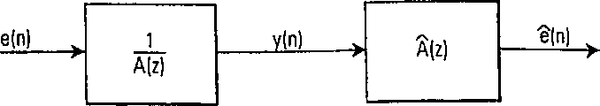
In Fig. 7, its black box that shows the AR processing represents that white noise e (n) encourages the full utmost point (all pole) system A
-1(z) so that produce an output signal y (n).In context, it is observable having only output signal y (n).For Fig. 5-0 or Fig. 5-1, output signal Y (n) is corresponding to RFE or RFE ' (perhaps being used for determining the signal TNE of spectral content, any one of TNE ').In addition, also we can say filter A
-1(z) can be considered to the voice range filter of remote speaker.Therefore, y (n) can be signal RFE.Significantly, signal e (n) is the far-end excitation.
In order to determine spectral content, need identification to produce the system of output signal y (n).Apparently, some simulation can be assumed to be it--providing a white noise list entries--, and generation can be described the output that is observed feature of observation signal y (n).For recognition methods is described, can suppose that output y (n) is an AR process, it usually is used a model as voice range.Output signal is fed in the identification block, and purpose is to obtain a kind of white output therein.
The black surround of the AR process of describing among Fig. 7 represents after this will be used to describe this identification.AR process y (n) is by the full electrode systems A of white-noise process e (n) excitation
-1(z) produce.In order to discern A
-1(z), use complete zero system
That is to say that ideally, zero will eliminate the utmost point of unknown system and therefore obtain e (n).
Unknown AR process can be defined as:
At this, q is a unit time shift operator.Now purpose be to locate by
The estimation of the y (n) of expression.Because the process y (n) that supposition is observed is an AR process, amount
Be adjusted so that e (n) becomes the white process of similar e (n).This adjustment is controlled by the one group of parameter that is included in the following vector:
a
T=[α
1...α
M] (2)
In principle, signal ê (n) can be found by following formula by filter y (n):
Note, by using the operator on the y (n)
(q; A), the summation in the equation (3) can be interpreted as the prediction based on the y (n) of the numerical value of the process y (n) that observed up to time n-1.Here,
 (q; A) corresponding to the filter G that describes among Fig. 5-0 and the 5-1.
Therefore, selected model structure (being AR here) and the parameter a that estimates are a description of the spectral content of y (n) together.That is to say shift operation in the alternative formula (1) symbol and estimate that left-hand side one side is in fact corresponding to the Fourier transform of y (n).
Yet the Fourier transform of random process is difficult to stipulate in theory.Therefore, define the frequency spectrum of random process according to auto correlation function.Yet as what see in equation (1), by having A (q) filtering y (n), all spectrum informations therefore can be deleted.
The estimation of filter parameter is directly, for example referring to the above-mentioned reference of Proakis and Manolakis.In fact, carrying out one in voice encryption device similarly estimates.This method of taking in the voice encryption device is based on the form of piece.Also can solve estimation by the gradient search procedure such as lowest mean square (LMS) algorithm.In order to explain this process, then will be necessary equational brief a derivation.Provide an input signal y (n), purpose is with the energy minimization in the signal.That is to say, minimize following:
At this y (n) is the estimated signal that is presented up to the sampling of time n-1.The minimum value of equation (4) will be the variance of white process.And it is a linear problem of guaranteeing to have a global minimum.Search parameter by separating by the equational linear system of V (a)/ a=0 definition.The LMS search utilizes the slope in the recurrence parameter update (it will stop when slope is zero), Adaptive Filter Theory. (sef-adapting filter theory) (Prentice Hall referring to S.Haykin., Englewood Cliffs, NJ1991, P.E.Gill, W.Murray) and the Practical Optirnization. of N.H.Wright. (actual optimization) (academic press, London 1981).That is to say:
At this, the direction that the μ decling phase is worked as.For the stability that keeps recursion equation formula (5) then often needs decay, this is a general knowledge, the Adaptive Filter Theory (sef-adapting filter theory) of S.Haykin, (Prentice-Hall, Englewood Cliffs, NJ, 1991).In addition, in LMS, desired value is replaced by the sudden approximation value:
a(n)=a(n-1)-μy(n-1)(y(n)-y(n-1)a
T) (6)
At this, y
T(n-1)=[y (n-1) ...., y (n-M-1)]
Just as already noted, use method can calculate model based on piece or sampling.Progressively, these methods equate., how many methods based on sampling may be more suitable for realizing in fixed point.If guarantee symmetrical Top thunder now the correlation method of structure be used then block-based method and carry out not too complicated.
In principle, the frequency spectrum that can carry out RFE or RFE ' is as described above determined.As what pointed out in the above, observation signal y (n) is corresponding to RFE or RFE ', and
 (q; A) corresponding to the filter G that describes among Fig. 5-0 and the 5-1.Notice that frequency spectrum is determined to come implicit expression to carry out by data being installed in the model here.
The insertion of parameter G model
(q; A) corresponding to the filter G that describes among Fig. 5-0 and the 5-1.Notice that frequency spectrum is determined to come implicit expression to carry out by data being installed in the model here.
The insertion of parameter G model
By adopting one or more top signals, all frequencies that filter G will decay relevant with remote signaling.Significantly, in bilateral words situation, decay also will influence adjacent speech., because near-end and far-end speech can be considered to be on the statistics independently process/signal, so can make (upgrading the G filter with special method) this influence be difficult to hear by selecting digital N.For example, suppose all parameters of calculating filter G of each frame.For fear of unexpected conversion, in the signal that will be launched, because the parameter among the change G can be used a kind of smoothing method.Realize that level and smooth a kind of method is following carrying out:
S1.G
old(q)=0_
S2. calculating filter G
Old(q) reflection coefficient
S3. (for example 160 sampling) come calculating filter G according to a new incoming frame
New(q) reflection coefficient
S4. at filter G
Old(q) and G
New(q) determine a straight line between the corresponding reflection coefficient
S5. for example select to comprise K=4 point on the line of end points, that is, and other two groups of reflection coefficients.Pass through Γ
βExpression reflection coefficient group, at this, β=1 ..., K.Note, with respect to from G
Old(q) to G
New(q) point on the line of scope is arranged group.
S6. utilize first group of reflection coefficient (promptly corresponding to G
Old(q)) filtering the one N/K sampling
S7. utilize these groups Γ
βCome N/K sampling of filtering β, at this
β=2,...,K
S8. allow G
Old(q)=G
New(q) and continue step S2.
Top process is roughly corresponding to a new filter on the sub-frame basis of estimating to be made up of N/K sampling.
The interests of top process are: it need accurately to determine less calculating than the filter that carries out based on subframe.
Spectrum estimation: use a kind of self adaptation nonparametric model
Hereinafter, will a example of utilizing nonparametric technique that use discrete Fourier transform to be used for determining spectral content be described.Spectral content determines that device CNT uses one of signal RFE, RFE ', TNE, TNE ', and preferably comprises the signal TNE ' or the TNE of residual echo.As explained above, when using signal TNE, TNE ' time, need voice activity detector VAD in the speech of near end signal pauses so that filter function calculating only is implemented.
Therefore; Determine that device CTL for example determines to comprise the subtracter output signal TNE ' of described residual echo signal or comprises the described discrete Fourier transform DFT that transmits of described echo-signal and the discrete Fourier transform DFT of described reception signal RFE, and according to from the described discrete Fourier transform DFT of the described TNE of transmitting that comprises described echo-signal or the ratio that from the described discrete Fourier transform DFT of the described subtracter output signal TNE ' that comprises described residual echo signal, deducts the described DFT DFT of described reception signal RFE represent to adjust filter parameter. That is to say, with the term of mathematics, this subtraction corresponding to:
T(ω
i)=M(ω
i)-αX(ω
i) (7)
At this, ω
iRepresent i frequency and the scale factor of discrete Fourier transform DFT respectively with α.As preceding mentioned, signal M in the equation (1) and X correspond respectively to and comprise the discrete Fourier transform of residual echo at interior signal (TNE ' or TNE) and remote signaling (RFE).Equation (5) can be transformed as follows:
Can see from equation (6): the filter function G that expects in the Fourier is:
Equation (5) or (6) are closely related with parametric technique, wherein, for example estimate a transfer function by autoregression external (ARX) model.Can be used in this class model of estimating filter function is for example described by the system identification (system identification) (Prentice-Hall International, London, 1998) of T.S derstr m and P.Stoika.This is fully aware of for the technical staff in signal processing and system identification field: many methods can be used for according to the needed information of spectral content of estimating to eliminate residual echo at the embodiment that preceding mentions.Therefore, a best mode that only should be used the present understanding of the present invention of conceiving of having described in the above as the inventor.The idea at center is to explore such fact: remote signaling is known and can be used to equally at the middle decay of signal TNE ' those spectral lines relevant with remote signaling FFE.Therefore, the filtered device G of residual echo suppresses fully.
The setting of G and voice activity detection
As mentioned above, first embodiment based on specified features be: do not need to revise the speech sign indicating number, so that background signal is synthesized.
As mentioned in the above, if signal TNE or signal TNE ' are used to estimate the spectral content relevant with received signal RFE, need then to be sure of that this is performed the time marquis who does not have near end signal to exist (, when the loud speaker of near-end transceiver unit TRU does not have speech) from transmitter MC.Therefore, VAD detector that need be shown in Fig. 5-1 so that spectral content determine device only operation calculate new filter function g, the G of adjacent speech in pausing.
In Fig. 5-1, first embodiment is described.Take on spectral content and determine that the unit far-end estimator FERST of a device part for example estimates the spectral characteristic of remote signaling in user's formula (1)-(6).In Fig. 5-1, signal REF ' is used, because it approaches the characteristic of remote signaling among the TNE.The unit that is called as INV more or less is inserted into an inversion model representing the far-end spectral characteristic and is used.Should be clear: in fact, can obtain this inversion model clearly by using a system identification method, and from DECOD equipment, can obtain in principle as the coefficient among the filter VTF that is used in as shown in Figure 4 by equation (3) expression.Therefore, equipment FEEST and INV form spectral content and determine device, and adjustment unit ADJ is provided to be provided with by signalization GC definite filter factor of filter G.
The use of VAD detector is chosen wantonly, and is promptly optional.Yet it has improved performance.In principle, VAD utilizes two signals so that determine bilateral words (DT) and the single conversation of far-end (FEST).Input to VAD is the signal relevant with far-end and near-end speaker.Attention: can use REF replacement REF ' and can use TNE to replace TNE '.Use the reason of TNE ' and REF ' to be: TNE ' does not comprise strong remote signaling (most of near end signal existence), and REF ' approaches the copy of the remote signaling among the TNE.Therefore, if signal TNE only comprises the far-end speech, detector VAD output FEST then is and if TNE comprises far-end and adjacent speech simultaneously, detector VAD output DT then.At last, if only there is adjacent speech, then VAD exports NEST.
Three of detector VAD output FEST, NEST and DT are sent to frame ADJ, and it is responsible for filter parameter is transferred to G.In addition, ADJ also is responsible for according to coming smoothing parameter as mentioned above.Come the mark among the self-detector VAD can be by the following use of ADJ.
Having only under the situation of adjacent speech, promptly NEST is for true DT and FEST are false, then do not carry out filtering and therefore this adjustment can force the model of G to trend towards homogeneous.In addition, also can carry out it for bilateral words, that is, DT be vacation for true FEST and NEST, so residual echo is shielded by near-end speaker.
At last, also can adjust as the gain of the function of frequency according to the signal among the VAD.If for example supposing this model is parameter, so by can change the gain as frequency function with respect to the mobile root radius of z area unit circle.The reason of doing like this is: the VAD detector can be indicated a continuous measurement (that is, a possibility and be not the binary variable of taking numerical value 0 and 1) of conversation, and carries out complete filtering when just a residual echo occurs in TNE '.When proximal promoter or when stopping, gain can move to homogeneous and move to overall gain from homogeneous from overall gain gradually respectively.Therefore, frame ADJ will based on signal DT, FEST and NEST adjusts from FEST to DT and DT to transition period of FEST and in the transition period of NEST to FEST and FEST to the NEST radial location of the root of G as mentioned above.
The second embodiment of the present invention
Second embodiment also is based on general structure as shown in Figure 5.In a second embodiment, residual echo suppression equipment G comprises a residual echo filter G that adjustable filter function g is arranged, and is suitable for emphasizing to transmit when speech pauses in the subtracter output signal TNE ' of subtracter ADD the background signal spectral content.For this purpose, control device CNT comprises a background signal model and determines device, and as among first embodiment, it uses one or more signal TNE, TNE ' to be used for estimating a background signal model according to one or more these signals.When the background signal model had been determined, the background signal model was determined device CNT according to determining that the background signal model is provided with the filter function g of residual echo filtering G, so so that the background signal spectral content emphasized.
When near end signal TNE is used to the background noise model when determining, schematically the VAD detector shown in Fig. 5-2 is used so that only determine the background noise model in speech pauses.Be this purpose, detector VAD receives subtracter input signal REF ' and subtracter output signal TNE ', and detects when not having speech in these two signals.If then VAD exports a true value in no conversation signal NT, and therefore switch SW is closed.Therefore, signal TNE or TNE ' are used to the background spectra estimation among the background spectra estimation unit BEST.When not having the far-end speech to exist, signal TNE and TNE ' can be used, so that determine the model of background noise.Yet the model that is obtained is to be used for the effective situation of remote signaling.That is to say that in speech paused, model was determined,, it be used in speech pause in and speech in the time interval.Therefore, in the method for second embodiment, carry out the following step: 1. when VAD detector output NT (not having the speech existence), a signal is obtained, and it is relevant with background signal (for example preferably TNE or TNE ').This signal is represented with " Y ".2. the model of the spectral content of selected signal Y is calculated in background spectra content estimation unit BEST, with the same among first embodiment, according to:
A) a kind of parametric approach; AR-for example, ARX-, the ARMA-Model parameter is estimated or the like; And/or
B) a kind of nonparametric technique, Fourier transform for example, wavelet conversion or the like.
This model of background noise is represented as " G ".3. by adjustment unit ADJ filter function g is set according to G, and signal TNE ' is filtered in filter G.
As explained above, signal among second embodiment occurs on sampling basis or frame basis, and carries out in those frames that the background noise simulation is determined and the calculating of filter transfer function G, g does not only have speech to exist for remote signaling RFE and near end signal TNE therein., according to the filter of having adjusted, background noise emphasize that (particularly also in Speech frame) is performed in all frames.
By having determined the background noise model according to one or more above-mentioned signals, the filter function of having adjusted will amplify the whole frequencies about background noise spectrum.Therefore, the frequency relevant with remote signaling RFE will be attenuated, unless remote signaling RFE has the spectral content identical with background noise., voice signal is to change the time, so voice spectrum also changes.Thereby voice signal will be attenuated.Therefore, residual echo is not emphasized with any system mode, and background signal will increase with the ratio that remains remote signaling.In context, relevant for the DTX working method of describing with reference to figure 2-1, Fig. 2-2, then one of two incidents of possibility may occur, that is:
Since do not comprise background noise in the frame of speech emphasize that the DTX working method of voice encryption device will start; With
2. shield the residue remote signaling by amplifying the frequency relevant with background process in the frame that comprises speech.
The improved form that should also be noted that second embodiment can also comprise a kind of long-term predictor, is used to carry out the long-term forecast of remote signaling so that eliminate remaining sound stimulation.
Above second embodiment, should be appreciated that the explanation, still in a second embodiment, do not revise code word, and the specified features of use filter G also is identical at the output of echo eliminator EC.Though the signal component about the speech of remote signaling RFE in first embodiment is attenuated, in a second embodiment, emphasize background noise about the remote signaling of receiving among the TNE with identical in essence effect.
In Fig. 5-2, second embodiment is described to echo cancellation device ECD.Notice that these pieces are similar to those of first embodiment, still, function is inequality.Here, VAD output no conversation signal NT, near-end single session signal NEST and bilateral words signal DT.When one of two signal TNE of signal NT control and TNE ' are used by switch SW by the BEST unit.Purpose is to want the estimated background signal in principle.Therefore, this can only just can carry out when middle not having near-end and do not have the far-end conversation signal to be presented on TNE and TNE '.Therefore, indicate by signal NT (not having conversation) the VAD unit does not have near-end and remote signaling.VAD decision signal NESTDT and NT are two signals (being respectively TNE ' and RFE ' in this case) based on observation and near-end and far-end.
As explained above, unit background estimating apparatus BEST estimates the spectral characteristic of during NT TNE or TNE '.The same with first embodiment, this estimation can be parameter or nonparametric.The spectral characteristic of estimated background is fed to the ADJ unit.
In a second embodiment, the main purpose of ADJ is that amplifilter G is set, the feasible spectral content that amplifies the TNE ' relevant with background spectra.Adjustment unit ADJ also can carry out shaping to the output of equipment B EST, so that can use homogeneous at when transmitting TNE (that is, when do not have remote signaling to be presented on) during the near-end single session.The same with first embodiment, the output Shaping of equipment B EST also can be with the termination of voice signal and begin relevant.That is to say that when NEST was indicated by the VAD piece, adjustment unit ADJ can little by little flatten the spectral shape of best estimate.On the other hand, when signal NEST indication did not have adjacent speech and signal DT not to indicate the bilateral words, the plane spectral characteristic of G can little by little increase, so that amplify the background signal among the TNE ' significantly.The DT mark can be used separately so that filter G is set to homogeneous.This is possible, because near end signal will shield the residual echo among the TNE '.Obviously, the ADJ unit can be considered to given with about the relevant given additional information of the speech activity of far-end and near end signal, be used to be provided with the device of filter G.
In the first embodiment of the present invention, a kind of filter G is designed, so that the decay spectral characteristic relevant with remote signaling.For simply, can suppose that the filter of determining according to first embodiment is complete zero filter (FIR), is represented as:
In a second embodiment, the filter G that has calculated and adjusted is used, so that emphasize (promptly amplifying) background signal about near-end one side.This filter can be estimated to be represented as a full utmost point filter (all pole filter):
Obviously, can merge the feasible filter that obtains the decay remote signaling and emphasize background signal of first and second embodiment.The filter that is obtained can be used as G, and it generally is an infinite impulse response (IIR) filter:
Therefore, first and second embodiment can be combined, that is, can carry out simultaneously with emphasize (promptly the amplifying) of the spectral content that transmits about the elimination of the spectral content of remote signaling.That is to say, spectral content about remote signaling is removed, and (in speech pauses, determining) emphasized about the background spectra content of near end signal (this model is determined in speech pauses, and in speech pauses and/or during speech activity, can amplify).
Third embodiment of the invention
Get in touch the present invention according to the 3rd embodiment, a kind of noise generation device NGN ' that is similar to shown in Fig. 2-2 can be used.In the 3rd embodiment, an additional noise generation device NGM may be provided in the output of echo cancellation device EC in essence, has placed another one adder ADD2 at this, and comparison diagram 5-0 and Fig. 5-3.
That is to say that among the 3rd embodiment that illustrates, adder ADD2 is used in Fig. 5-3 block diagram., comparison diagram 2-2 or 2-3, the noise process that should be pointed out that introducing are directly relevant with background noise process and the noise changed.The noise process of introducing is based on background spectra and uses TNE ' to come weighting.Weighting is used to shield the residual echo of noise process.The shield door limit value can be according to calculating with the similar approach described in the following book: " the Transform coding of audio signals usingperceptual noise criteria " of J.D.Jonston (using the transform coding of the audio signal of consciousness noise criteria), IEEE Journal on selected areas in communications (about selecting the I EEE periodical in field in the communication) (pp.314-323,1988 the 6th volume 314-323 pages or leaves).In principle, as get off to calculate weighting function.
1. use the spectral content that calculates TNE ' based on Bark (bark) yardstick of N sampling, be at least 320 at this N;
2. the Bark frequency spectrum with TNE ' comes the convolution spread function;
3. the result's that standardizes again w.r.t. spread function.
4. the result of the background spectra (utilizing the bark yardstick) of BEST estimation among Fig. 5-3 with step 3 compared.
5. in step 4, draw the amplitude that increases background spectra under the bigger situation of step 3.
Basically, top process purpose is to increase residual echo to contribute the spectrum energy that background spectra is estimated in the zone of power.The result of step 3 can be considered to a shield door limit value, and the additional noise level that its indication exceeds threshold value will be felt.
In fact, threshold value not necessarily must be revisable, and for example each frame all recomputates.During the information of average residual echo spectrum content can perform well in calculating.
Therefore, the whole processing that obtained approach background signal, but still have the information about remote signaling RFE.
In addition, should be clear: the noise signal of increase be the estimated form of the background signal of relevant with the spectral shape of residual echo (long or short-term) stack additional noise process.
By at first considering to be appreciated that essential benefit to a noise process of subtracter output signal TNE ' increase as Fig. 2-2 and the described prior art of Fig. 2-3.Just as can be seen, two figure comprise the switch SW of being controlled by some logic (detector VAD) 1.Obviously, performance depends on to a great extent how good the control logic running is.That is to say, if the system representation that is used among Fig. 2-2 and Fig. 2-3 does not have near end signal TNE, and in fact a near end signal TNE exists, and then the speech information among the TNE that transmits of Chuan Songing is replaced by noise.Very clear, this situation is not expected.
The 3rd present embodiment will be passed to the distal side under the situation that appears at the near end signal among the TNE ' suddenly.This mainly is because the power averaging of adder ADD2 equals the fact of the power of TNE ' causes.Because the calculating carried out is based on a long-term relatively basis (for example using the described average frequency spectrum information as residual echo signal), so very clear: because different in spectral shape and the power, the shield door limit value can not be hidden near end signal.
At last, very clear: signal REF ' or REF can be used, so that the shield door limit value of calculation expectation.Use the major advantage of REF ' or REF to be: in those signals, near end signal will never occur.Therefore, the spectral content of REF ' or REF must not be not only filtered in a filter of imitation echo eliminator EC effect, so that obtain the signal that frequency spectrum approaches residual signal.Use this method, the noise signal of introducing can be recomputated.The same with the schematic block diagram among Fig. 5-3, in the 3rd embodiment, near-end speech activity detector VAD also is essential, is used to detect single session/bilateral words situation.
In Fig. 5-0, the whole principle of three embodiment of the present invention is described.There is shown a piece that is called control unit CTL at this.According to the 3rd embodiment, the controller chassis CTL shown in Fig. 6 (it shows the Combination Control frame of Fig. 5-0 to Fig. 5-3) operates according to above-mentioned.That is to say that threshold value is calculated and is based on REF ' (REF is not expressed) and TNE '.This information is fed back to the model that is used for producing according to overall gain k and spectral shape adjustment a suitable noise sequence.Conventional method utilization such as parameter or the nonparametric method is determined original background signal by spectrum estimation.Attention: in piece, carry out this operation among Fig. 6 by " background simulated estimation " expression.In addition, when local VAD signal indication uses signal TNE ' (or the TNE that transmits) to be used for the spectral content estimation by far-end single session (FEST) and near-end single session (NEST).
Other embodiment of the present invention
As explained above, first to the 3rd embodiment can operate respectively, that is, be removed according to the spectral content of the first embodiment received signal; Emphasized (promptly amplifying) according to the second embodiment background noise; And according to the 3rd embodiment, a noise process is introduced into.
Yet first and second embodiment can be merged, that is, removing of spectral content can be emphasized to combine with the background noise of second embodiment.That is to say, be removed, and (determining in speech pauses) emphasized by (in speech pauses and/or during speech activity) about the background spectra content of near end signal about the spectral content of remote signaling.
The 3rd embodiment can be used with first and second embodiment.For example, shown in Fig. 5-0, before the voice encryption device input, can place another one adder ADD2.One of two inputs of adder ADD2 are the attenuated form (that is, being attenuated according to first and/or second embodiment) of TNE '.Second input is an artificial background signal NC.Now, TNE ' is attenuated with respect to the energy in the background signal, that is to say:
At this, when not having near-end and not having remote signaling existence and x (n) when being TNE, E
bEstimated.Then, following operation is implemented:
At this, A is from a synthetic background signal among the AR+NC, and the same among filter G and embodiment one or two.Note,
By scale, and A does not have.Therefore, but voice encryption device will obtain being arranged by background noise still be not relevant with a background signal.
The 3rd embodiment can be used with the second and the 3rd embodiment.First embodiment calculates a filter, and its frequency spectrum approaches the contrary of residual echo signal.Obviously, most of residual echo is eliminated., because various restrictions, non-linear and so on such as loud speaker is so may expect the 3rd embodiment is used method as the end residual echo.This can realize by the output of G being fed back among the threshold value calculating adjustment unit ADJ as shown in Figure 6.
When combining with second embodiment, the 3rd embodiment can be to calculate as basic according to the threshold value of the output of filter G (with having adjusted according to second embodiment is the same).
Certainly, in the combination of the embodiment of the invention, can comprise the method for echo cancellation of explaining with reference to device NCM shown in Fig. 2-1,2-2 and 2-3 and device MSIDM, eliminate so that further improve echo.
As aforesaid, Fig. 6 represents the interaction of three embodiment.In Fig. 6, show a conventional controller CTL.Therefore the unit that is positioned at controller CTL inside is as first, second and Fig. 5-1, the 5-2 of the 3rd embodiment, the set of the unit shown in the 5-3.As what in Fig. 6, can see, adjust device A DJ and comprise two, that is, and as threshold value computing equipment and the combiner device described in the 3rd embodiment.Combiner device is the molecule of the model of first and second embodiment that represented by equation (12) and denominator combination.In addition, combiner can be used for relying on the state of VAD output control signal NEST, FEST and DT (NT can obtain from these two signals) to adjust the radius of the zero-sum utmost point of filter function g.In piece NCM ', another one gain constant k can be by additional.If desired, then gain constant is used to the power output of adjusting module NCM '.Signal MASK-AR is the shielding frequency spectrum, and it produces in the 3rd embodiment and it is sent to piece NCM ' and AR unit.
Industrial applicibility of the present invention
As explained above, the present invention can be used among any transceiver unit TRU of telecommunication system TELE, and no matter communication process is radio communication or wire communication.In addition, the present invention is not treated to the basis in the frame mode of signal yet in principle.Though the sound coupling is the main coupling effect of considering among the present invention, other residual echo that is caused by electric capacity between reception and the part and/or inductance coupling high also can be eliminated.Though explained the present invention with reference to the signal that appears in the telecommunications transceiver machine, very clear: the signal of the system that any other closed loop problem that is caused by coupling (therefore producing echo) exists can be used.
In addition, should be pointed out that the present invention is not restricted to described embodiment and example, and scope of the present invention is limited by accessory claim just.As explained above, the present invention can comprise in the accessory rights requirement and the characteristic described respectively in the specification in and the embodiment that comes.Therefore, the foregoing description just is considered to inventor's design at present as the embodiment of optimal mode of the present invention.
Reference number in the claim just is used for clearly purpose, and is not to limit the scope of the invention.
The tabulation of ginseng person's number
The ADD musical instruments used in a Buddhist or Taoist mass
ADJ adjusts
The ANT antenna
The AR autoregression
The AR-PAR auto-regressive parameter
BEST background estimating device
The CNT controller
The COD encoder
The DECOD decoder
DT bilateral words
The discontinuous transmission of DTX
The EC wave excluder
The EST estimator
The FE far-end
FEEST far-end estimator
FEST far-end single session
The FR full rate
GC filter G control
The GSM global system for mobile communications
INV is contrary
LAR daily record region rate
The MC transmitter
MSID makes SID
The control of NC noise
The NE near-end
NEST near-end single session
The NG noise generator
NGM noisemaker device
NT does not have conversation
The PNC pseudo noise generator
The RC radio-circuit
The RF radio frequency
The far-end that RFE receives
The far-end of the reception of RFE ' H output
The far-end of the coding speech that RFESC receives
RPE-LTP Regular-Pulse Excitation-long-term forecast
The noiseless descriptor of SID
SNG composite noise generator
The SP loud speaker
SPECOD voice encryption device unit
The SW switch
The TELE phone
TNE launches near-end
Emission near-end after the TNE ' EC
The TRU transceiver unit
The TR transmitter unit
The TX transmitter
The VAD voice activity detector
Claims (26)
1. an echo cancellation device (ECD), be used for eliminating the received signal of being received by the receiving element (RX) of the transceiver unit (TRU) of telecommunication system (TELE) (RFE) and be coupled to its caused echo of transmitter unit (TR), this echo cancellation device (ECD) comprising:
A) transfer function estimator (EST, H), be suitable for estimating from receiving element (RC, SP is RCRT) to transmitter unit (TR, MC, coupling transfer function TCRT), and be used to utilize the coupling transfer function (H) of described estimation to handle received signal (RFE);
B) subtracter (ADD), be suitable for from comprise by received signal (RFE) to transmitter unit (MC, the caused echo-signal of coupling TCRT) deducts the received signal (RFE ') of processing in interior transmitting (TNE); With
C) residual echo suppression equipment is used for suppressing the residual echo of subtracter output signal (ADD);
It is characterized in that:
D) described residual echo suppression equipment comprises a residual echo filter (G) that adjustable filter function (g) is arranged, and is suitable for eliminating and the relevant spectral characteristic of received signal (RFE) from the subtracter output signal (TNE ') of subtracter (ADD).
2. equipment as claimed in claim 1 (ECD) is characterized in that:
A spectral content is determined device (CTL), be suitable for receiving described received signal (RFE) and/or comprise by received signal (RFE) and be coupled to transmitter unit (MC, TCRT) caused described echo-signal is in the received signal (RFE ') and/or the subtracter output signal (TNE ') of interior described transmitting (TNE) and/or described processing, so that determine and the relevant spectral content of received signal (RFE), and the filter function (g) of described residual echo filter (G) is set according to determined spectral content according to one or more these signals.
3. equipment as claimed in claim 2 (ECD) is characterized in that:
Described spectral content determines that device (CTL) comprises a voice activity detector (VAD), be used for determining a speech activity in described transmitting (TNE) that comprises described echo-signal and/or received signal (RFE ') and/or in subtracter output signal (TNE ') in described processing, have only when described voice activity detector (VAD) does not detect any speech activity in described signal, described spectral content determines that device (CTL) determines that a spectral content is relevant with the received signal in comprising described the transmitting (TNE) of described echo-signal and/or in subtracter output signal (TNE ').
4. equipment as claimed in claim 2 (ECD) is characterized in that:
Described residual echo filter (G) is a digital filter, and its filtering characteristic is determined by one group of adjustable filter parameter.
5. equipment as claimed in claim 4 (ECD) is characterized in that:
Described spectral content determines that device (CTL) is by estimating one or more described signal (RFE; TNE; RFE; RFE '; TNE ') linear model (A (z
-1)) model parameter determine the frequency spectrum designation of signal separately, determine the contrary (A of described linear model
-1) parameter, and the tunable filter parameter is set to described inversion model (A
-1) parameter so that eliminate and the relevant spectral content of described received signal (RFE).
6. equipment as claimed in claim 5 (ECD) is characterized in that:
Described linear model is autoregression (AG) model or a kind of autoregression external (ARX) model from the residual echo to the remote signaling.
7. the described equipment of claim 5 (ECD) is characterized in that:
Described definite device (CTL) is determined the discrete Fourier transform (DFT) of described the transmitting (TNE) that comprise the described subtracter output signal (TNE ') of described residual echo signal or comprise described echo-signal and the discrete Fourier transform (DFT) of described reception signal (RFE), and according to from the described discrete Fourier transform (DFT) of described the transmitting (TNE) that comprise described echo-signal or the ratio that from the described discrete Fourier transform (DFT) of the described subtracter output signal (TNE ') that comprises described residual echo signal, deducts the described discrete Fourier transform (DFT) of described reception signal (RFE) represent that (α) adjusts described filter parameter.
8. the described equipment of claim 7 (ECD) is characterized in that:
The described filter operations that obtains by the filter parameter that described digital filter is set is confirmed as:
G(ω
i)=(1-αX(ω
i)/M(ω
i)) (2)
At this, G (ω
i) be the discrete Fourier transform of filter function g, X (ω
i) be the discrete Fourier transform of received signal, M (ω
i) be comprise described echo-signal described transmitting (TNE) discrete Fourier transform or from the described discrete Fourier transform (DFT) of the described subtracter output signal (TNE ') that comprises described residual echo signal, and α is a scale factor.
9. equipment as claimed in claim 1 (ECD) is characterized in that:
A list/bilateral words detector (VAD, DT), be suitable for detecting described received signal (RFE) and/or comprise by received signal (RFE) transmitter unit (MC, TCRT) the caused described echo-signal of coupling is used for determining the speech activity that receives and/or transmit in interior described transmitting (TNE) and/or a speech transmissions in described processed received signal (RFE ') and/or the subtracter output signal (TNE ').
10. equipment as claimed in claim 9 (ECD) is characterized in that:
(VAD DT) determines in described received signal speech activity to be arranged and when not having speech activity in described transmitting, described adjustable filter function (g) Be Controlled circuit (CTL) is adjusted to an all pass circuit when described list/bilateral words detector;
As described list/bilateral words detector (VAD, DT) determine in described received signal, there is not speech activity and in described transmitting during the beginning of a speech activity, when described adjustable filter function (g) when being controlled to all pass circuit, described adjustable filter function (g) is maintained at the all-pass state;
As described list/bilateral words detector (VAD, DT) determine that speech activity is arranged and in described received signal during the beginning of a speech activity in described transmitting, when described adjustable filter function (g) when being controlled to all pass circuit, described adjustable filter function (g) Be Controlled is so that spectral content is lowered to a certain degree; With
As described list/bilateral words detector (VAD, DT) determine described in described transmitting a speech activity stop and in described received signal during the beginning of a speech activity, described adjustable filter function (g) Be Controlled is so that spectral content is eliminated.
11. equipment as claimed in claim 1 (ECD) is characterized in that:
Described adjustable filter function (g) also is suitable for: amplify in the subtracter output signal (TNE ') of subtracter (ADD) by described transmitter unit (TR, TCRT) spectral content of background signal in transmit (TNE, the TNE ') of emission.
12. equipment as claimed in claim 11 (ECD) is characterized in that:
At the described (TNE that transmits, TNE ') during pausing, speech determines the background spectra content, and in speech pauses and/or in described transmitting (TNE, TNE '), carry out described amplification, always carry out the spectral content relevant simultaneously and eliminate with received signal (RFE).
13. equipment as claimed in claim 1 (ECD) is characterized in that:
Noise generation device (NGM '; AR ADD2), is suitable for increasing noise in the filtering output signal (TNE ') in the spectral range relevant with received signal (RFE), is used to shield residual echo.
A 14. echo cancellation device (ECD), be used for eliminating the received signal of being received by the receiving element (RX) of the transceiver unit (TRU) of telecommunication system (TELE) (RFE) and be coupled to its caused echo of transmitter unit (TR), this echo cancellation device (ECD) comprising:
A) transfer function estimator (EST, H), be suitable for estimating from receiving element (RX, SP is RCRT) to transmitter unit (TR, MC, coupling transfer function TCRT), and be used to utilize the coupling transfer function (H) of described estimation to handle received signal (RFE);
B) subtracter (ADD), be suitable for from comprise by received signal (RFE) to transmitter unit (MC, the caused echo-signal of coupling TCRT) deducts the received signal (RFE ') of processing in interior transmitting (TNE); With
C) residual echo suppression equipment is used for suppressing the residual echo of subtracter output signal (ADD);
It is characterized in that:
D) described residual echo suppression equipment (G) comprises the residual echo filtering (G) with adjustable filter function (g), be suitable in the subtracter output signal (TNE ') of subtracter (ADD), amplifying by described transmitter unit (TR, TCRT) background signal spectral content in transmit (TNE, the TNE ') of emission.
15. equipment as claimed in claim 14 (ECD) is characterized in that:
A background signal model is determined device (CTL), be suitable for receiving and comprise by received signal (RFE) and be coupled to transmitter unit (MC, TCRT) caused described echo-signal is in interior described transmitting (TNE) and/or subtracter output signal (TNE '), so that determine a background signal model according to one or more these signals, and according to determined background signal model the filter function (g) of described residual echo filter (G) is set, so that emphasize the background signal spectral content.
16. equipment as claimed in claim 15 (ECD) is characterized in that:
Described background signal model determines that device (CTL) comprises a voice activity detector (VAD), be used for determining to comprise described the transmitting (TNE) and/or the speech activity in subtracter output signal (TNE ') of described echo-signal, described background signal model determines that device (CTL) has only a model just determining described background signal when described voice activity detector (VAD) does not detect any speech activity in described signal.
17. equipment as claimed in claim 14 (ECD) is characterized in that:
Described adjustable filter function (g) is also applicable to eliminating and the relevant spectral characteristic of received signal (RFE) from the subtracter output signal (TNE ') of subtracter (ADD).
18., it is characterized in that as claim 14 or 17 described equipment (ECD):
Noise generation device (NGM '; AR ADD2), is suitable for increasing noise in the filtering output signal (TNE ') in the spectral range relevant with received signal (RFE), is used to shield residual echo.
A 19. echo cancellation device (ECD), be used for eliminating the received signal (RFE) received by the receiving element (RX) of the transceiver unit (TRU) of telecommunication system (TELE) the caused echo of coupling to its transmitter unit (TR), this echo cancellation device (ECD) comprising:
A) transfer function estimator (EST, H), be suitable for estimating from receiving element (RX, SP is RCRT) to transmitter unit (TR, MC, coupling transfer function TCRT), and be used to utilize the coupling transfer function (H) of described estimation to handle received signal (RFE);
B) subtracter (ADD), be suitable for from comprise by received signal (RFE) to transmitter unit (MC, the caused echo-signal of coupling TCRT) deducts the received signal (RFE ') of processing in interior transmitting (TNE); With
C) residual echo suppression equipment is used for suppressing the residual echo of subtracter output signal (ADD);
It is characterized in that:
D) described residual echo suppression equipment (G) include the residual echo filter (G) of adjustable filter function (g) and noise generation device (NGM '; AR ADD2), is suitable for increasing noise in the filtering output signal in the spectral range relevant with received signal (RFE), is used to shield residual echo.
20. equipment as claimed in claim 19 (ECD) is characterized in that:
A spectral content is determined device (CTL), be suitable for receiving described received signal (RFE) and/or comprise by received signal (RFE) transmitter unit (MC, TCRT) the caused described echo-signal of coupling is in the received signal (RFE ') and/or the subtracter output signal (TNE ') of interior described transmitting (TNE) and/or described processing, so that determine and the relevant spectral range of received signal (RFE) according to one or more these signals.
21. equipment as claimed in claim 19 (ECD) is characterized in that:
By control device (CTL) described filter function (g) is adjusted into all-pass filter.
22. equipment as claimed in claim 19 (ECD) is characterized in that:
Described noise generation device (NGM ') comprises a kind of AR model unit (AR) by a noise generator (NG) excitation, wherein, an adjustment unit (ADJ) is provided for the described AR of control unit a needed spectral shape of shielding residual echo is set.
23. equipment as claimed in claim 19 (ECD) is characterized in that:
Described adjustable filter function (g) is applicable to eliminating and the relevant spectral characteristic of received signal (RFE) from the subtracter output signal (TNE ') of subtracter (ADD).
24., it is characterized in that as claim 19 or 23 described equipment (ECD):
Described adjustable filter function (g) also is suitable for amplifying in the subtracter output signal (TNE ') of subtracter (ADD) by described transmitter unit (TR, TCRT) spectral content of background signal in transmit (TNE, the TNE ') of emission.
25. one kind comprises as the transceiver unit (TRU) of the one or more described echo cancellation device (EC) of claim 1-16, it is characterized in that:
Described receiving element (RX; SP) comprise the loud speaker (SP) of exporting described received signal (RFE), and described biography transmitter unit (TR, MC) comprise a transmitter (MC) that produces described transmitting (TNE), wherein, described echo is caused by a sound coupling between loud speaker (SP) and the transmitter (MC).
26. one kind comprise as the one or more described echo cancellation device (ECD) of claim 1-17 and at the voice encryption device (COD) in this echo cancellation device (ECD) downstream at interior transceiver unit (TRU).
Applications Claiming Priority (2)
| Application Number | Priority Date | Filing Date | Title |
|---|---|---|---|
| DE19935808A DE19935808A1 (en) | 1999-07-29 | 1999-07-29 | Echo suppression device for suppressing echoes in a transmitter / receiver unit |
| DE19935808.7 | 1999-07-29 |
Publications (1)
| Publication Number | Publication Date |
|---|---|
| CN1451225A true CN1451225A (en) | 2003-10-22 |
Family
ID=7916580
Family Applications (1)
| Application Number | Title | Priority Date | Filing Date |
|---|---|---|---|
| CN00813663A Pending CN1451225A (en) | 1999-07-29 | 2000-07-28 | Echo cancellation device for cancelling echos in a transceiver unit |
Country Status (9)
| Country | Link |
|---|---|
| US (1) | US6597787B1 (en) |
| EP (1) | EP1208689B1 (en) |
| JP (1) | JP2003506924A (en) |
| CN (1) | CN1451225A (en) |
| AT (1) | ATE308201T1 (en) |
| AU (1) | AU6160800A (en) |
| DE (2) | DE19935808A1 (en) |
| MY (1) | MY133285A (en) |
| WO (1) | WO2001010102A2 (en) |
Cited By (2)
| Publication number | Priority date | Publication date | Assignee | Title |
|---|---|---|---|---|
| CN109618380A (en) * | 2019-01-03 | 2019-04-12 | 中国联合网络通信集团有限公司 | A kind of Internet of Things network reselection method, apparatus and system |
| CN113541733A (en) * | 2021-09-17 | 2021-10-22 | 北京国科天迅科技有限公司 | Equalization and echo cancellation device, method, computer device and storage medium |
Families Citing this family (77)
| Publication number | Priority date | Publication date | Assignee | Title |
|---|---|---|---|---|
| US6766019B1 (en) * | 2000-07-21 | 2004-07-20 | Agere Systems Inc. | Method and apparatus for performing double-talk detection in acoustic echo cancellation |
| US6751203B1 (en) * | 2000-08-21 | 2004-06-15 | Lucent Technologies Inc. | Methods and apparatus for the production of echo free side tones |
| US6876699B1 (en) | 2000-08-29 | 2005-04-05 | Lucent Technologies Inc. | Filter circuit for a bit pump and method of configuring the same |
| US6970511B1 (en) | 2000-08-29 | 2005-11-29 | Lucent Technologies Inc. | Interpolator, a resampler employing the interpolator and method of interpolating a signal associated therewith |
| US6973146B1 (en) | 2000-08-29 | 2005-12-06 | Lucent Technologies Inc. | Resampler for a bit pump and method of resampling a signal associated therewith |
| US6983047B1 (en) * | 2000-08-29 | 2006-01-03 | Lucent Technologies Inc. | Echo canceling system for a bit pump and method of operating the same |
| US6894989B1 (en) | 2000-08-29 | 2005-05-17 | Agere Systems Inc. | Separation circuit for an echo canceling system and method of operating the same |
| US6813351B1 (en) * | 2000-11-21 | 2004-11-02 | Motorola, Inc. | Method and apparatus for echo cancellation that suppresses echo leak through |
| US20030097267A1 (en) * | 2001-10-26 | 2003-05-22 | Docomo Communications Laboratories Usa, Inc. | Complete optimization of model parameters in parametric speech coders |
| US7050545B2 (en) * | 2001-04-12 | 2006-05-23 | Tallabs Operations, Inc. | Methods and apparatus for echo cancellation using an adaptive lattice based non-linear processor |
| JP3536921B2 (en) * | 2001-04-18 | 2004-06-14 | 日本電気株式会社 | Correlation matrix learning method, apparatus and program |
| US6985550B2 (en) * | 2001-04-30 | 2006-01-10 | Agere Systems Inc. | Jitter control processor and a transceiver employing the same |
| GB2375688B (en) * | 2001-05-14 | 2004-09-29 | Motorola Ltd | Telephone apparatus and a communication method using such apparatus |
| US20020172350A1 (en) * | 2001-05-15 | 2002-11-21 | Edwards Brent W. | Method for generating a final signal from a near-end signal and a far-end signal |
| DE10139403A1 (en) * | 2001-08-10 | 2003-02-27 | Tenovis Gmbh & Co Kg | Method for bridging over toneless voice pauses during a telecom link with subscribers connected via a digital network causes a voice signal being transmitted to fall short of a preset minimum level in a set transmission time span. |
| JP3568922B2 (en) | 2001-09-20 | 2004-09-22 | 三菱電機株式会社 | Echo processing device |
| US7085715B2 (en) * | 2002-01-10 | 2006-08-01 | Mitel Networks Corporation | Method and apparatus of controlling noise level calculations in a conferencing system |
| JP4161628B2 (en) | 2002-07-19 | 2008-10-08 | 日本電気株式会社 | Echo suppression method and apparatus |
| US7233896B2 (en) * | 2002-07-30 | 2007-06-19 | Motorola Inc. | Regular-pulse excitation speech coder |
| US7672445B1 (en) * | 2002-11-15 | 2010-03-02 | Fortemedia, Inc. | Method and system for nonlinear echo suppression |
| US7627111B2 (en) * | 2002-11-25 | 2009-12-01 | Intel Corporation | Noise matching for echo cancellers |
| US7272224B1 (en) * | 2003-03-03 | 2007-09-18 | Apple Inc. | Echo cancellation |
| US7274732B2 (en) * | 2003-03-21 | 2007-09-25 | Texas Instruments Incorporated | Echo cancellation in communication systems with asymmetric data rates |
| US7243065B2 (en) * | 2003-04-08 | 2007-07-10 | Freescale Semiconductor, Inc | Low-complexity comfort noise generator |
| US7599432B2 (en) | 2003-12-08 | 2009-10-06 | Freescale Semiconductor, Inc. | Method and apparatus for dynamically inserting gain in an adaptive filter system |
| WO2006040734A1 (en) * | 2004-10-13 | 2006-04-20 | Koninklijke Philips Electronics N.V. | Echo cancellation |
| US8457614B2 (en) | 2005-04-07 | 2013-06-04 | Clearone Communications, Inc. | Wireless multi-unit conference phone |
| US7711107B1 (en) * | 2005-05-12 | 2010-05-04 | Mindspeed Technologies, Inc. | Perceptual masking of residual echo |
| JP4696776B2 (en) * | 2005-08-17 | 2011-06-08 | ソニー株式会社 | Audio processing device and microphone device |
| US20080119165A1 (en) * | 2005-10-03 | 2008-05-22 | Ajay Mittal | Call routing via recipient authentication |
| JP4536020B2 (en) * | 2006-03-13 | 2010-09-01 | Necアクセステクニカ株式会社 | Voice input device and method having noise removal function |
| EP1855456B1 (en) | 2006-05-08 | 2009-10-14 | Harman/Becker Automotive Systems GmbH | Echo reduction in time-variant systems |
| US7565159B2 (en) * | 2006-06-14 | 2009-07-21 | Divitas Networks, Inc. | Methods and arrangement for implementing an active call handover by employing a switching component |
| US20080140767A1 (en) * | 2006-06-14 | 2008-06-12 | Prasad Rao | Divitas description protocol and methods therefor |
| US7480500B1 (en) | 2006-06-14 | 2009-01-20 | Divitas Networks, Inc. | Divitas protocol proxy and methods therefor |
| EP2055018A4 (en) | 2006-06-14 | 2009-09-16 | Divitas Networks Inc | Code-based echo cancellation |
| US20090016333A1 (en) * | 2006-06-14 | 2009-01-15 | Derek Wang | Content-based adaptive jitter handling |
| US20080317241A1 (en) * | 2006-06-14 | 2008-12-25 | Derek Wang | Code-based echo cancellation |
| US8369511B2 (en) * | 2006-12-26 | 2013-02-05 | Huawei Technologies Co., Ltd. | Robust method of echo suppressor |
| US20080159551A1 (en) * | 2006-12-28 | 2008-07-03 | Texas Instruments Incorporated | System and Method for Acoustic Echo Removal (AER) |
| US8526645B2 (en) * | 2007-05-04 | 2013-09-03 | Personics Holdings Inc. | Method and device for in ear canal echo suppression |
| CN101578659B (en) * | 2007-05-14 | 2012-01-18 | 松下电器产业株式会社 | Voice tone converting device and voice tone converting method |
| CN101689371B (en) * | 2007-06-21 | 2013-02-06 | 皇家飞利浦电子股份有限公司 | A device for and a method of processing audio signals |
| US8199927B1 (en) | 2007-10-31 | 2012-06-12 | ClearOnce Communications, Inc. | Conferencing system implementing echo cancellation and push-to-talk microphone detection using two-stage frequency filter |
| US8050398B1 (en) | 2007-10-31 | 2011-11-01 | Clearone Communications, Inc. | Adaptive conferencing pod sidetone compensator connecting to a telephonic device having intermittent sidetone |
| KR101444099B1 (en) * | 2007-11-13 | 2014-09-26 | 삼성전자주식회사 | Method and apparatus for detecting voice activity |
| KR100844176B1 (en) | 2008-01-25 | 2008-07-07 | 재단법인서울대학교산학협력재단 | A method for suppressing a residual echo based on statistical model |
| US20090215438A1 (en) * | 2008-02-23 | 2009-08-27 | Ajay Mittal | Methods for performing transparent callback |
| JP4631933B2 (en) * | 2008-05-30 | 2011-02-16 | 日本電気株式会社 | Echo suppression method |
| US8958441B2 (en) | 2008-06-05 | 2015-02-17 | Qualcomm Incorporated | System and method of an in-band modem for data communications over digital wireless communication networks |
| US9083521B2 (en) | 2008-06-05 | 2015-07-14 | Qualcomm Incorporated | System and method of an in-band modem for data communications over digital wireless communication networks |
| US8964788B2 (en) | 2008-06-05 | 2015-02-24 | Qualcomm Incorporated | System and method of an in-band modem for data communications over digital wireless communication networks |
| US8825480B2 (en) | 2008-06-05 | 2014-09-02 | Qualcomm Incorporated | Apparatus and method of obtaining non-speech data embedded in vocoder packet |
| US8503517B2 (en) | 2008-06-05 | 2013-08-06 | Qualcomm Incorporated | System and method of an in-band modem for data communications over digital wireless communication networks |
| US8725502B2 (en) | 2008-06-05 | 2014-05-13 | Qualcomm Incorporated | System and method of an in-band modem for data communications over digital wireless communication networks |
| TWI465122B (en) | 2009-01-30 | 2014-12-11 | Dolby Lab Licensing Corp | Method for determining inverse filter from critically banded impulse response data |
| US20100222053A1 (en) * | 2009-02-27 | 2010-09-02 | Girisrinivasarao Athulurutirumala | Arrangement and methods for establishing a telecommunication connection based on a heuristic model |
| US8743864B2 (en) | 2009-06-16 | 2014-06-03 | Qualcomm Incorporated | System and method for supporting higher-layer protocol messaging in an in-band modem |
| US8855100B2 (en) | 2009-06-16 | 2014-10-07 | Qualcomm Incorporated | System and method for supporting higher-layer protocol messaging in an in-band modem |
| US8462193B1 (en) * | 2010-01-08 | 2013-06-11 | Polycom, Inc. | Method and system for processing audio signals |
| JP5156043B2 (en) * | 2010-03-26 | 2013-03-06 | 株式会社東芝 | Voice discrimination device |
| US9065895B2 (en) * | 2012-02-22 | 2015-06-23 | Broadcom Corporation | Non-linear echo cancellation |
| US8964967B2 (en) * | 2012-12-07 | 2015-02-24 | Dialog Semiconductor B.V. | Subband domain echo masking for improved duplexity of spectral domain echo suppressors |
| US9100466B2 (en) * | 2013-05-13 | 2015-08-04 | Intel IP Corporation | Method for processing an audio signal and audio receiving circuit |
| GB201309779D0 (en) | 2013-05-31 | 2013-07-17 | Microsoft Corp | Echo removal |
| GB201309773D0 (en) * | 2013-05-31 | 2013-07-17 | Microsoft Corp | Echo removal |
| US9544702B2 (en) * | 2013-07-23 | 2017-01-10 | Mitel Networks Corporation | Dynamic characterization of a communication device |
| GB2547063B (en) * | 2014-10-30 | 2018-01-31 | Imagination Tech Ltd | Noise estimator |
| GB2532041B (en) * | 2014-11-06 | 2019-05-29 | Imagination Tech Ltd | Comfort noise generation |
| US9712866B2 (en) | 2015-04-16 | 2017-07-18 | Comigo Ltd. | Cancelling TV audio disturbance by set-top boxes in conferences |
| CN108140395B (en) * | 2015-09-25 | 2022-01-04 | 美高森美半导体(美国)股份有限公司 | Comfort noise generation apparatus and method |
| US10122863B2 (en) | 2016-09-13 | 2018-11-06 | Microsemi Semiconductor (U.S.) Inc. | Full duplex voice communication system and method |
| CN111863000A (en) * | 2019-04-30 | 2020-10-30 | 北京嘀嘀无限科技发展有限公司 | Audio processing method and device, electronic equipment and readable storage medium |
| US11170760B2 (en) * | 2019-06-21 | 2021-11-09 | Robert Bosch Gmbh | Detecting speech activity in real-time in audio signal |
| CN111031448B (en) * | 2019-11-12 | 2021-09-17 | 西安讯飞超脑信息科技有限公司 | Echo cancellation method, echo cancellation device, electronic equipment and storage medium |
| CN112946608A (en) * | 2021-01-29 | 2021-06-11 | 中国科学院半导体研究所 | Laser target simulator with background light simulation |
| US20230412727A1 (en) * | 2022-06-20 | 2023-12-21 | Motorola Mobility Llc | Adjusting Transmit Audio at Near-end Device Based on Background Noise at Far-end Device |
Family Cites Families (23)
| Publication number | Priority date | Publication date | Assignee | Title |
|---|---|---|---|---|
| US4609787A (en) * | 1984-05-21 | 1986-09-02 | Communications Satellite Corporation | Echo canceller with extended frequency range |
| JPS6342527A (en) | 1986-08-08 | 1988-02-23 | Oki Electric Ind Co Ltd | Digital subscriber's line transmission equipment |
| US5157653A (en) | 1990-08-03 | 1992-10-20 | Coherent Communications Systems Corp. | Residual echo elimination with proportionate noise injection |
| FR2675648B1 (en) * | 1991-04-19 | 1993-08-20 | France Telecom | DEVICE FOR PROCESSING THE RESIDUAL ECHO OF A CANCER OF THE ECHO SIGNAL OF A DIGITAL SPOKEN SIGNAL. |
| US5222251A (en) | 1992-04-27 | 1993-06-22 | Motorola, Inc. | Method for eliminating acoustic echo in a communication device |
| US5307405A (en) | 1992-09-25 | 1994-04-26 | Qualcomm Incorporated | Network echo canceller |
| JP2626437B2 (en) | 1992-12-28 | 1997-07-02 | 日本電気株式会社 | Residual echo control device |
| US5475731A (en) * | 1994-01-07 | 1995-12-12 | Ericsson Inc. | Echo-canceling system and method using echo estimate to modify error signal |
| US5621800A (en) * | 1994-11-01 | 1997-04-15 | Motorola, Inc. | Integrated circuit that performs multiple communication tasks |
| SE505156C2 (en) * | 1995-01-30 | 1997-07-07 | Ericsson Telefon Ab L M | Procedure for noise suppression by spectral subtraction |
| US5600718A (en) * | 1995-02-24 | 1997-02-04 | Ericsson Inc. | Apparatus and method for adaptively precompensating for loudspeaker distortions |
| US5680450A (en) * | 1995-02-24 | 1997-10-21 | Ericsson Inc. | Apparatus and method for canceling acoustic echoes including non-linear distortions in loudspeaker telephones |
| FI110826B (en) * | 1995-06-08 | 2003-03-31 | Nokia Corp | Eliminating an acoustic echo in a digital mobile communication system |
| US5561668A (en) | 1995-07-06 | 1996-10-01 | Coherent Communications Systems Corp. | Echo canceler with subband attenuation and noise injection control |
| US5937060A (en) * | 1996-02-09 | 1999-08-10 | Texas Instruments Incorporated | Residual echo suppression |
| KR100482396B1 (en) * | 1996-05-31 | 2005-08-04 | 코닌클리케 필립스 일렉트로닉스 엔.브이. | Device for suppressing interference component of input signal |
| US6185300B1 (en) * | 1996-12-31 | 2001-02-06 | Ericsson Inc. | Echo canceler for use in communications system |
| EP0895688B1 (en) * | 1997-01-23 | 2006-02-15 | Motorola, Inc. | Apparatus and method for non-linear processing in a communication system |
| US5920834A (en) * | 1997-01-31 | 1999-07-06 | Qualcomm Incorporated | Echo canceller with talk state determination to control speech processor functional elements in a digital telephone system |
| FI104524B (en) * | 1997-04-18 | 2000-02-15 | Nokia Mobile Phones Ltd | An echo cancellation system and method and a mobile station |
| JP3361724B2 (en) | 1997-06-11 | 2003-01-07 | 沖電気工業株式会社 | Echo canceller device |
| DE19729521B4 (en) * | 1997-07-10 | 2004-04-01 | Deutsche Telekom Ag | Method and device for suppressing noise and echo |
| US6163608A (en) * | 1998-01-09 | 2000-12-19 | Ericsson Inc. | Methods and apparatus for providing comfort noise in communications systems |
-
1999
- 1999-07-29 DE DE19935808A patent/DE19935808A1/en not_active Ceased
-
2000
- 2000-07-21 MY MYPI20003351 patent/MY133285A/en unknown
- 2000-07-28 WO PCT/EP2000/007321 patent/WO2001010102A2/en active IP Right Grant
- 2000-07-28 US US09/628,932 patent/US6597787B1/en not_active Expired - Lifetime
- 2000-07-28 AU AU61608/00A patent/AU6160800A/en not_active Abandoned
- 2000-07-28 CN CN00813663A patent/CN1451225A/en active Pending
- 2000-07-28 EP EP00948012A patent/EP1208689B1/en not_active Expired - Lifetime
- 2000-07-28 AT AT00948012T patent/ATE308201T1/en not_active IP Right Cessation
- 2000-07-28 JP JP2001513872A patent/JP2003506924A/en not_active Withdrawn
- 2000-07-28 DE DE60023515T patent/DE60023515D1/en not_active Expired - Lifetime
Cited By (3)
| Publication number | Priority date | Publication date | Assignee | Title |
|---|---|---|---|---|
| CN109618380A (en) * | 2019-01-03 | 2019-04-12 | 中国联合网络通信集团有限公司 | A kind of Internet of Things network reselection method, apparatus and system |
| CN113541733A (en) * | 2021-09-17 | 2021-10-22 | 北京国科天迅科技有限公司 | Equalization and echo cancellation device, method, computer device and storage medium |
| CN113541733B (en) * | 2021-09-17 | 2022-01-28 | 北京国科天迅科技有限公司 | Equalization and echo cancellation device, method, computer device and storage medium |
Also Published As
| Publication number | Publication date |
|---|---|
| WO2001010102A3 (en) | 2002-03-14 |
| DE60023515D1 (en) | 2005-12-01 |
| EP1208689A2 (en) | 2002-05-29 |
| WO2001010102A2 (en) | 2001-02-08 |
| MY133285A (en) | 2007-10-31 |
| DE19935808A1 (en) | 2001-02-08 |
| EP1208689B1 (en) | 2005-10-26 |
| JP2003506924A (en) | 2003-02-18 |
| AU6160800A (en) | 2001-02-19 |
| US6597787B1 (en) | 2003-07-22 |
| ATE308201T1 (en) | 2005-11-15 |
Similar Documents
| Publication | Publication Date | Title |
|---|---|---|
| CN1451225A (en) | Echo cancellation device for cancelling echos in a transceiver unit | |
| CN1171202C (en) | Noise suppression | |
| CN1041374C (en) | Network echo canceller | |
| CN1145931C (en) | Signal noise reduction by spectral substration using linear convolution and causal filtering | |
| CN1223109C (en) | Enhancement of near-end voice signals in an echo suppression system | |
| CN1218506C (en) | Method and apparatus for using state determination to control functional elements | |
| CN1284139C (en) | Noise reduction method and device | |
| CN1267891C (en) | Voice communication system and method for processing drop-out fram | |
| US9082389B2 (en) | Pre-shaping series filter for active noise cancellation adaptive filter | |
| US7558729B1 (en) | Music detection for enhancing echo cancellation and speech coding | |
| CN1595827A (en) | Digital adaptive filter and acoustic echo canceller using the same | |
| CN1504042A (en) | Audio signal quality enhancement in a digital network | |
| CN1176034A (en) | Apparatus and method for canceling acoustic echoes including non-linear distortions in loudspeaker telephones | |
| CN1669074A (en) | Voice intensifier | |
| CN1689069A (en) | Sound encoding apparatus and sound encoding method | |
| CN1111973C (en) | Echo cancelling system for digital telephony applications | |
| CN1284309C (en) | Echo killer and leanring method used thereof | |
| CN103460613A (en) | A computation saving echo canceller for a wide band audio signal | |
| CN1136374A (en) | Transmitter-receiver | |
| EP1515307A1 (en) | Method and apparatus for audio coding with noise suppression | |
| JP4261622B2 (en) | Non-linear processing apparatus and method in communication system | |
| US8406430B2 (en) | Simulated background noise enabled echo canceller | |
| CN1682280A (en) | Method and system for controlling potentially harmful signals in a signal arranged to convey speech | |
| JP2007189536A (en) | Acoustic echo canceler, acoustic error canceling method and speech communication equipment | |
| JP2002064617A (en) | Echo suppression method and echo suppression equipment |
Legal Events
| Date | Code | Title | Description |
|---|---|---|---|
| C06 | Publication | ||
| PB01 | Publication | ||
| C10 | Entry into substantive examination | ||
| SE01 | Entry into force of request for substantive examination | ||
| C02 | Deemed withdrawal of patent application after publication (patent law 2001) | ||
| WD01 | Invention patent application deemed withdrawn after publication |