CN1401408A - Air filter and air conditioning device - Google Patents
Air filter and air conditioning device Download PDFInfo
- Publication number
- CN1401408A CN1401408A CN02131803A CN02131803A CN1401408A CN 1401408 A CN1401408 A CN 1401408A CN 02131803 A CN02131803 A CN 02131803A CN 02131803 A CN02131803 A CN 02131803A CN 1401408 A CN1401408 A CN 1401408A
- Authority
- CN
- China
- Prior art keywords
- air
- air cleaner
- front panel
- filter
- heat exchanger
- Prior art date
- Legal status (The legal status is an assumption and is not a legal conclusion. Google has not performed a legal analysis and makes no representation as to the accuracy of the status listed.)
- Granted
Links
Images




Classifications
-
- F—MECHANICAL ENGINEERING; LIGHTING; HEATING; WEAPONS; BLASTING
- F24—HEATING; RANGES; VENTILATING
- F24F—AIR-CONDITIONING; AIR-HUMIDIFICATION; VENTILATION; USE OF AIR CURRENTS FOR SCREENING
- F24F13/00—Details common to, or for air-conditioning, air-humidification, ventilation or use of air currents for screening
- F24F13/28—Arrangement or mounting of filters
-
- F—MECHANICAL ENGINEERING; LIGHTING; HEATING; WEAPONS; BLASTING
- F24—HEATING; RANGES; VENTILATING
- F24F—AIR-CONDITIONING; AIR-HUMIDIFICATION; VENTILATION; USE OF AIR CURRENTS FOR SCREENING
- F24F1/00—Room units for air-conditioning, e.g. separate or self-contained units or units receiving primary air from a central station
- F24F1/0007—Indoor units, e.g. fan coil units
- F24F1/0035—Indoor units, e.g. fan coil units characterised by introduction of outside air to the room
-
- F—MECHANICAL ENGINEERING; LIGHTING; HEATING; WEAPONS; BLASTING
- F24—HEATING; RANGES; VENTILATING
- F24F—AIR-CONDITIONING; AIR-HUMIDIFICATION; VENTILATION; USE OF AIR CURRENTS FOR SCREENING
- F24F1/00—Room units for air-conditioning, e.g. separate or self-contained units or units receiving primary air from a central station
- F24F1/0007—Indoor units, e.g. fan coil units
- F24F1/0043—Indoor units, e.g. fan coil units characterised by mounting arrangements
- F24F1/0057—Indoor units, e.g. fan coil units characterised by mounting arrangements mounted in or on a wall
Landscapes
- Engineering & Computer Science (AREA)
- Chemical & Material Sciences (AREA)
- Combustion & Propulsion (AREA)
- Mechanical Engineering (AREA)
- General Engineering & Computer Science (AREA)
- Air Filters, Heat-Exchange Apparatuses, And Housings Of Air-Conditioning Units (AREA)
- Filtering Of Dispersed Particles In Gases (AREA)
Abstract
一种分别具有过滤体(3)并用铰链(23)将多个单元过滤器框架部件(22)连接起来的可自由弯折的空气过滤器(14),所述相互连接的单元过滤器框架部件具有插入设置在空气过滤器(14)的设置场所上的导向槽(26)的导向部(32),在单元过滤器(14)的两侧面(35)上分别设有由突出的至少一对凸台部(25)构成的导向部(32)。
A freely bendable air filter (14) which has filter bodies (3) respectively and connects a plurality of unit filter frame parts (22) by hinges (23), the interconnected unit filter frame parts There is a guide part (32) inserted into the guide groove (26) on the installation place of the air filter (14), and at least one pair of protrusions are respectively provided on both sides (35) of the unit filter (14). The guide part (32) formed by the boss part (25).
Description
技术领域technical field
本发明涉及一种空气过滤器和装有这种空气过滤器的空调装置。The present invention relates to an air filter and an air conditioner equipped with the air filter.
背景技术Background technique
过去的空调装置的空气过滤器采用记载在日本特开平6-226024号公报中的技术。图5表示记载在上述公报中的空气过滤器的透视图。在图5中,附图标记1表示空气过滤器,2表示平板形的单元过滤器部件,由于这种过滤器需要具有去除灰尘的过滤功能和在弯折时具有铰链功能,所以它用聚乙烯或尼龙等一般树脂材料的纯净材料制作。但是,上述单元过滤器部件2由后述的框体片6保持在过滤体3的两侧,各单元过滤器部件2仅由过滤体3构成,利用两侧边未保持在框体片6上的铰链4部可自由弯折地连接在一起。The air filter of conventional air conditioners employs the technology described in Japanese Patent Application Laid-Open No. 6-226024. Fig. 5 shows a perspective view of the air filter described in the above publication. In Fig. 5, reference numeral 1 denotes an air filter, and 2 denotes a flat-shaped unit filter part. Since this filter needs to have a filtering function for removing dust and a hinge function when bent, it is made of polyethylene. Or nylon and other general resin materials made of pure materials. However, the above-mentioned unit filter parts 2 are held on both sides of the filter body 3 by the frame body sheet 6 described later, and each unit filter part 2 is only composed of the filter body 3, and is not held on the frame body sheet 6 by the two sides. The 4 parts of the hinge can be freely bent and connected together.
框体片6是用聚乙烯等树脂与过滤体3成一体地模铸而成的。在框体片6上设有平框7和把手8。框体片6具有能嵌合在空调装置10的配合槽11内的形状,长度为由这种框体片保持的单元过滤器部件2的铰链部4,4之间的间隔稍短一些,并在左右对称的位置上配置多个。而且为了容易将框体片6插入配合槽11内,另外,为了在弯折时不使框体片6的角部分相碰,在框体片6的两个端部设置倒角9。平框7成对地设置在空气过滤器体1的上部和下部,同时形成上下框架,并与左右框体片6成一整体。把手8设置在平框7的下侧用于空气过滤器1向空调装置10上安装时将手握在该把手上,以便操作空气过滤器1。The frame piece 6 is integrally molded with the filter body 3 using a resin such as polyethylene. A flat frame 7 and a handle 8 are provided on the frame sheet 6 . The frame piece 6 has a shape that can be fitted into the matching groove 11 of the air conditioner 10, and the length is such that the distance between the hinge parts 4 and 4 of the unit filter member 2 held by the frame piece is slightly shorter, and A plurality of them are arranged at bilaterally symmetrical positions. Furthermore, chamfers 9 are provided at both ends of the frame piece 6 to facilitate insertion of the frame piece 6 into the fitting groove 11 and to prevent the corners of the frame piece 6 from colliding when bent. The flat frames 7 are arranged in pairs on the upper and lower parts of the air filter body 1 , forming upper and lower frames at the same time, and are integrated with the left and right frame pieces 6 . The handle 8 is arranged on the lower side of the flat frame 7 for holding the hand on the handle when the air filter 1 is installed on the air conditioner 10 so as to operate the air filter 1 .
下面将对空气过滤器1的安装方法进行说明。Next, a method of installing the air filter 1 will be described.
如图5所示,在安装空气过滤器1时,将空气过滤器1朝空调装置10的空气进气口13的下侧方向弯曲的同时,将平框7的前端插入安装口12中。并且使左右框体6嵌合在安装口12两端的配合槽11内。同样,使其余的框体片6与铰链部4垂直地复位时,也就顺次地将它们插入到空调器10的配合槽11中。然后再用手操作把手8,以插入最后一对框体片6,从而将空气过滤器推入。As shown in FIG. 5 , when installing the air filter 1 , the front end of the flat frame 7 is inserted into the installation port 12 while bending the air filter 1 toward the lower side of the air inlet 13 of the air conditioner 10 . And the left and right frame bodies 6 are fitted into the matching grooves 11 at both ends of the installation opening 12 . Similarly, when the rest of the frame pieces 6 are vertically returned to the hinge portion 4, they are inserted into the fitting groove 11 of the air conditioner 10 in sequence. The handle 8 is then manually operated to insert the last pair of frame pieces 6, thereby pushing the air filter in.
另外,把手8从空调装置10的安装口12的下侧伸出,因而很容易将空气过滤器1取出。在取出空气过滤器1时,握住并提拉从安装口12下侧伸出的把手8,可将框体片6从空调装置10的配合槽11中顺次拉出。而且,在使铰链部4笔直地复位的同时,可将空气过滤器1从空调装置10的下侧取出。In addition, the handle 8 protrudes from the lower side of the installation port 12 of the air conditioner 10, so that the air filter 1 can be easily taken out. When taking out the air filter 1, hold and pull the handle 8 protruding from the lower side of the installation opening 12, and the frame piece 6 can be pulled out sequentially from the matching groove 11 of the air conditioner 10. Also, the air filter 1 can be taken out from the lower side of the air conditioner 10 while the hinge portion 4 is straightly returned.
现有的这种空调装置10的空气过滤器1,为了将空气过滤器1安装到空调装置10上,需将两侧边的框体片6插入配合槽11,但由于框体片6在插入方向上太长,所以在配合槽11弯曲的情况下,存在很难顺利地安装空气过滤器1的问题。For the air filter 1 of the existing air conditioner 10, in order to install the air filter 1 on the air conditioner 10, the frame pieces 6 on both sides need to be inserted into the matching grooves 11, but since the frame pieces 6 are inserted The direction is too long, so when the fitting groove 11 is bent, there is a problem that it is difficult to install the air filter 1 smoothly.
另外,在将空气过滤器1从空调装置10取出时,在将两侧边的框体片6插入配合槽11的同时,需将过滤体3等连续地插入形成于配合槽11内的相同开口宽度的安装口12中。因此,过滤体等的厚度不能大于框体片6的厚度。这样就存在着不能为提高过滤体的空调净化功能加大过滤体的厚度的问题。In addition, when the air filter 1 is taken out from the air conditioner 10, while the frame pieces 6 on both sides are inserted into the fitting groove 11, it is necessary to continuously insert the filter body 3 etc. into the same opening formed in the fitting groove 11. Width of the mounting port 12. Therefore, the thickness of the filter body and the like cannot be larger than the thickness of the frame sheet 6 . Like this, there is a problem that the thickness of the filter body cannot be increased for improving the air-conditioning purification function of the filter body.
另外,图15、16表示出例如特开平10-232025号公报中的现有空调装置(室内机)。15 and 16 show, for example, a conventional air conditioner (indoor unit) disclosed in JP-A-10-232025.
在图16中,由于设置在上部吸气格栅107左右两侧的凹状槽部107a可在位于前面板105上部左右两边的导轨105a上滑动,从而可将上部吸气格栅107安装在前面板105上。这样就将空气过滤器分成前后两部分,后部空气过滤器110安装在上部吸气格栅107上,并随着上部吸气格栅的安装而被安装。In Fig. 16, since the concave grooves 107a arranged on the left and right sides of the upper
由于现有的空调装置中可拆装的上部吸气格栅和空气过滤器具有上述结构,所以上部吸气格栅必须和左右导轨配合地安装,虽然可蹬上椅子或桌子在高处进行安装操作,但在这种位置上必然会带来操作上的困难。另外,空气过滤器被分成前后两部分,特别是后部空气过滤器固定在上部吸气格栅上,所以降低了上部吸气格栅的安装操作性,而且还需花费时间对过滤器进行清洗,此外,还增加了制造成本。Because the detachable upper air intake grille and air filter in the existing air conditioner have the above-mentioned structure, the upper air intake grille must be installed in cooperation with the left and right guide rails, although it can be installed on a chair or table at a high place Operation, but in this position will inevitably bring operational difficulties. In addition, the air filter is divided into front and rear parts, especially the rear air filter is fixed to the upper suction grille, so the installation operability of the upper suction grille is reduced, and it takes time to clean the filter , in addition, also increases the manufacturing cost.
发明内容Contents of the invention
本发明是为了解决上述问题而提出的,达到使开始是弯曲形状的空气过滤器能顺利地安装到具有自由形状的导轨槽内的目的。The present invention is proposed in order to solve the above-mentioned problems, so as to achieve the purpose of smoothly installing the curved air filter into the free-shaped guide rail groove.
本发明的另一个目的是:获得过滤体可以是任意厚度,并可提高性能的空气过滤器。Another object of the present invention is to obtain an air filter whose filter body can be of any thickness and whose performance can be improved.
本发明的再一个目的是:获得在空调装置运行时,很难由于振动而发出“劈劈”噪声的空气过滤器。Yet another object of the present invention is to obtain an air filter which hardly makes a "cracking" noise due to vibrations when the air conditioner is in operation.
本发明的另一个目的是:获得在安装空调装置时,不容易从导向槽中滑脱出来的空气过滤器。Another object of the present invention is to obtain an air filter that is not easy to slip out of the guide groove when the air conditioner is installed.
本发明还有一个目的是:获得能够以较低的成本制造的空气过滤器。Yet another object of the invention is to obtain an air filter that can be manufactured at relatively low cost.
本发明的另一个目的是:提供一种安装这种空气过滤器的高品质、高性能的空调装置及提供一种能防止热交换器污染的空调装置。Another object of the present invention is to provide a high-quality, high-performance air conditioner equipped with such an air filter and to provide an air conditioner capable of preventing contamination of a heat exchanger.
本发明再一个目的是:提供一种上部吸气格栅安装操作简单并可简化清扫操作的空调装置。Another object of the present invention is to provide an air conditioner which is easy to install and operate on the upper suction grille and can simplify the cleaning operation.
利用记载的权利要求所限定的本发明可实现上述这些目的。These objects are achieved by the invention defined in the appended claims.
附图的简要说明Brief description of the drawings
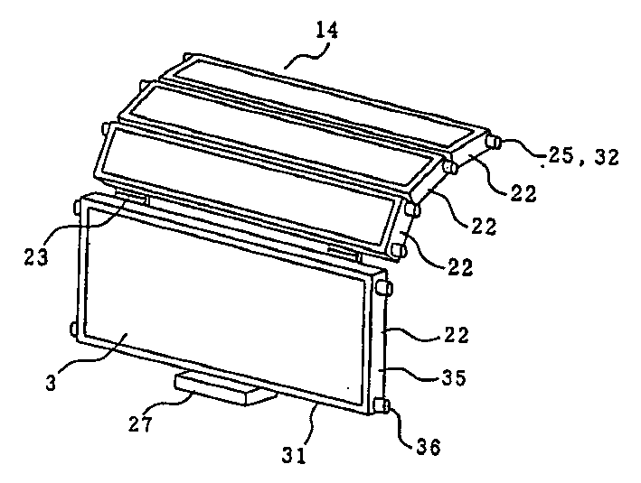
图1是本发明第一实施例的空气过滤器的透视图;Fig. 1 is the perspective view of the air filter of the first embodiment of the present invention;
图2是本发明第一实施例的空调装置的剖视图;Fig. 2 is a sectional view of the air conditioner according to the first embodiment of the present invention;
图3是本发明第二实施例的空气过滤器的局部结构图;3 is a partial structural view of an air filter according to a second embodiment of the present invention;
图4是本发明的第三实施例的楔状导向部及导向槽的示意图;4 is a schematic diagram of a wedge-shaped guide portion and a guide groove according to a third embodiment of the present invention;
图5是现有空气过滤器的透视图;Figure 5 is a perspective view of an existing air filter;
图6是本发明第四实施例的空调装置的剖视图;6 is a sectional view of an air conditioner according to a fourth embodiment of the present invention;
图7是本发明第四实施例的空调装置的主要部分的透视图;7 is a perspective view of a main part of an air conditioner according to a fourth embodiment of the present invention;
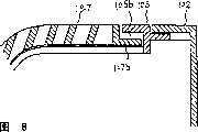
图8是表示本发明第四实施例的上部吸气格栅前端部的前面板安装部分的放大剖视图;8 is an enlarged cross-sectional view showing a front panel mounting portion of the front end portion of an upper air intake grill according to a fourth embodiment of the present invention;
图9是表示本发明第四实施例的上部吸气格栅后端部的前面板固定部分的放大剖视图;9 is an enlarged cross-sectional view showing a front panel fixing portion of the rear end portion of the upper air intake grill according to the fourth embodiment of the present invention;
图10是表示卡止部件的装配部的平面剖视图;Fig. 10 is a planar cross-sectional view showing the mounting part of the locking member;
图11是表示卡止部件的装配部的透视图;Fig. 11 is a perspective view showing an assembly portion of a locking member;
图12是前部吸气格栅处于抬起时的空调装置的剖视图。Fig. 12 is a sectional view of the air conditioner when the front air intake grill is raised.
图13是本发明第五实施例的上部吸气格栅的装配平面图;Fig. 13 is an assembly plan view of the upper suction grille of the fifth embodiment of the present invention;
图14是本发明第六实施例的上部吸气格栅的后端部的放大剖视图;Fig. 14 is an enlarged cross-sectional view of the rear end of the upper suction grill according to the sixth embodiment of the present invention;
图15是现有的空调装置的横剖视图;Fig. 15 is a cross-sectional view of an existing air conditioner;
图16是现有的空调装置的局部放大视。Fig. 16 is a partially enlarged view of a conventional air conditioner.
发明的具体实施方式Specific Embodiments of the Invention
第一实施例first embodiment
下面将参照图1、图2解释本发明的第一实施例。A first embodiment of the present invention will be explained below with reference to FIGS. 1 and 2 .
图1是第一实施例的空气过滤器的透视图。图2是安装有空气过滤器的空调装置(或空调制冷装置)的剖视图。Fig. 1 is a perspective view of an air filter of a first embodiment. Fig. 2 is a cross-sectional view of an air conditioner (or air conditioner and refrigeration device) equipped with an air filter.
在图1-图2中,设置在室内的空调装置15的面板16的前部设有空气吸入口的格栅17,该空气吸入口格栅17的背后内置有送风机19及遮盖住该送风机19地配置的热交换器18。在面板16的下部设有空气吹出口20,利用风门21可对空气吹出口20的开关及吹风方向进行调整。In Fig. 1-Fig. 2, be arranged on the front portion of the panel 16 of air-
在格栅17与热交换器18之间,与热交换器18的断面相配合地安装空气过滤器14。利用多个铰链23将装有具有去除灰尘等过滤功能的平板型过滤体3的单元过滤器框架部件22可自由弯折地连接在一起,并全部遮挡住上述热交换器18。Between the grill 17 and the heat exchanger 18, the air filter 14 is attached so that the cross section of the heat exchanger 18 may fit. A plurality of hinges 23 are used to connect the unit
在上述单元过滤器框架部件22的两个侧面35上分别具有至少一个凸台部25,在面板16上设有与该凸台部25相配合的弯曲的嵌合槽26,仅有上述的凸台部25从后面将要描述的插入部28的安装口40处插入并安装在上述嵌合槽26内。There are at least one
空气过滤器14由装有过滤体3的、通过铰链23连接的多个单元过滤器框架部件22及用作导向部32的凸台部25等构成。The air filter 14 is composed of a plurality of unit
用作导向部32的上述凸台部25是从单元过滤器框架部件22的相对两侧面35处伸出的圆柱部件,由于每侧面至少有一个圆柱部件伸出,两侧面有一对圆柱部件伸出。在图2中示出了有1对和2对圆柱部件的实例。The above-mentioned
用作导向槽的上述嵌合槽26刚好能从用作上述导向部32的凸台部25的两侧容纳该凸台部25,使两侧的开口部相对的向,在上述嵌合槽26的插入方向上形成コ字形断面。The above-mentioned fitting groove 26 used as a guide groove can just accommodate the
如图2所示,嵌合槽26的插入部28由断面为コ字形的安装口40和从安装口40向下方延伸的支承板41构成。但是,根据具体形状,即使插入部28不设置支承板41,只设安装口40也是可以的。As shown in FIG. 2 , the insertion portion 28 of the fitting groove 26 is composed of a mounting opening 40 having a U-shaped cross section and a support plate 41 extending downward from the mounting opening 40 . However, depending on the specific shape, even if the support plate 41 is not provided on the insertion portion 28, only the mounting opening 40 may be provided.
在相互连接的单元过滤器框架部件22的最后一个单元过滤器框架部件22的端部装有在装配过滤器14时用于操作的把手27。At the end of the last unit
另外,利用树脂材料,很容易整体成型地制造这种单元过滤器框架部件22、铰链部23、凸台部25及把手27。In addition, the unit
下面将对空气过滤器14的安装方法进行说明。Next, a method of installing the air filter 14 will be described.
虽然对不同机种的空调装置来说,其安装方法也不同,但都要进行开启格栅17和拆卸空气过滤器14等操作。在安装空气过滤器14时,从空调装置15的空气吸入口17的下侧将空气过滤器14插入嵌合槽26的安装口40内,并将单元过滤器框架部件22的凸台部25用插入的方式装配到嵌合槽26内。另外,通过操作把手27插入空气过滤器14,直到将最后一对凸台部25插入为止。Though for the air conditioner of different models, its installation method is also different, but all will carry out operations such as opening grille 17 and dismantling air filter 14. When installing the air filter 14, the air filter 14 is inserted into the installation port 40 of the fitting groove 26 from the underside of the air intake port 17 of the
另外,在拆卸空气过滤器14时,将把手27向操作者方向拉,使铰链部23变直,同时将单元过滤器框架部件22的凸台部25顺次拉出嵌合槽26。In addition, when detaching the air filter 14, the handle 27 is pulled toward the operator to straighten the hinge portion 23, and at the same time, the
在安装时,使具有把手27的单元过滤器框架部件22(具有把手27的最后一个单元过滤器框架部件22)处于上述支承板41上之后,安装是很容易进行的。At the time of installation, after the unit
如上所述,将凸台部25设置在单元过滤器框架部件22的侧面35上,为了使凸台部25与设置在面板16上的嵌合槽26相配合,不管过滤体3是否为平板状,不管过滤体3与嵌合槽26的开口宽度方向相对处的厚度有多厚,也不管嵌合槽26是否全面覆盖住热交换器18地弯曲,在这些情况下都能顺利地将空气过滤器14相对用作导向槽的嵌合槽26进行安装。As mentioned above, the
另外,在安装空气过滤器14时,仅将两侧的凸台部25插入到导向槽26内,并且由于相互连接的单元过滤器框架部件22是自由的,所以过滤体3的厚度可比导向槽26的开口宽度更厚,这样就能使用高性能的过滤体,从而可提高空气过滤器的性能。In addition, when installing the air filter 14, only the
另外,可将位于热交换器18的风道的上游处的导向槽26设计成沿热交换器18弯曲的,将导向部32插入导向槽26内后,由于在安装空气过滤器14时,为使其覆盖热交换器18而弯曲地安装,从而使提供给热交换器18的空气大部分都从空气过滤器14中通过,从而可确实地防止热交换器18被污染。此外,由于设置了与弯曲配置的热交换器18相对应的弯曲的导向槽26,所以使空调装置15变得更加紧凑。In addition, the guide groove 26 located at the upstream of the air duct of the heat exchanger 18 can be designed to be bent along the heat exchanger 18. After the
另外,如图2所示,在嵌合槽26的曲率大的部分,用在单元过滤器框架部件22的插入方向的长度较小的单元过滤器框架部件,这样从总体上说,空气过滤器14非常适合于弯曲,热交换器18也非常适合于弯曲,这样可防止供给的空气不通过空气过滤器14地流向热交换器18,同时有效地使空调装置15更加小型化。In addition, as shown in FIG. 2, in the part where the curvature of the fitting groove 26 is large, a unit filter frame member with a relatively small length in the insertion direction of the unit
而且,在单元过滤器框架部件22的插入方向的长度较小的情况下,即使长度较小的单元过滤器框架部件22、不具有凸台部25的单元过滤器框架部件22及具有凸台部25的单元过滤器框架部件22混在一起,也不会防碍相互连接的单元过滤器框架部件22的安装,并可获得具有相同效果的空气过滤器14。这样就使空气过滤器14的制作简单化了。Moreover, when the length of the insertion direction of the unit
第二实施例second embodiment
在第一实施例中,在单元过滤器框架部件22的两侧35至少伸出1个凸台部25,该凸台部25插在面板16的弯曲的嵌合槽26内,安装上相互连接的单元过滤器框架部件22,而在本实施例中,如图3所示,在单元过滤器框架部件22的两侧面35的凸台部25之间,相同侧面35的凸台部25连接在作为弹性体的、可变形的平板状导向带29上。由该凸台部25及与凸台部相连的导向带29构成的导向部32被插在面板16的弯曲的嵌合槽26内,安装上相互连接的单元过滤器框架部件22。In the first embodiment, at least one
导向带29沿单元过滤器框架部件22的各凸台部25的侧面37形成,并与相邻的凸台部25的侧面37的前侧或后侧统一相连。这样,在将导向部32插入嵌合槽26内的情况下,前侧就是图2的空气吸入口的格栅17那侧,后侧就是上述前侧的相反侧。The
另外,如图3所示,为了在导向带29和凸台部25的侧面37在嵌合槽26内相对于嵌合槽26的内壁滑动时使两者处于同一滑动面,通过将凸台部25的安装侧面37消除导向带29的厚度,将导向带29安装在凸台部25上,从而可更加顺利地进行安装。In addition, as shown in FIG. 3 , in order to make both the
平板状的导向带29配置在单元过滤器框架部件22的前面,这样,在安装空气过滤器14时,不会干扰嵌合槽26的安装口40,从而提高了安装特性。The
另外,平板状导向带29、单元过滤器框架部件22侧面35的凸台部25是用树脂材料整体成型制造的,这样就降低了制造成本。In addition, the
导向带29的连接也可以不是在单元过滤器框架部件22的侧面35的凸台部25的整体上进行,而是部分实施。例如,在图2的空调装置中,在安装空气过滤器14时,可以用导向带29连接从导向槽26的安装口40容纳在前端部分38内的凸台部25,位于支承板部件41的凸台部25不用导向带29连接。这样可得到相同的效果。The connection of the
如上所示,由于有本发明实施例的导向部32,所以在从插入部28的安装口40处插入嵌合槽26时,可防止凸台部25从嵌合槽26中滑出,从而可更加顺利地安装空气过滤器14。As shown above, due to the
第三实施例third embodiment
在第一、第二实施例中,设置在单元过滤器框架部件22侧面35的凸台部25向外伸出方向的断面36的尺寸是相同的,但如图4所示,在本实施例中,凸台部25的断面36的尺寸,如凸台部25a,25b,25,25d那样越靠近嵌合槽26的安装口40处(空气过滤器的导向部的插入口侧)尺寸越大,整个导向部32形成楔状,另外,嵌合槽26也与该导向部32相配合形成楔形,因此,在装配时,凸台部25与嵌合槽26之间可无间隙地装配,以确保空气过滤器14保持在面板16上,从而可防止运行的空调装置15在振动时发出劈劈的噪声,并可提供质量优良的空调装置15。In the first and second embodiments, the size of the section 36 of the
在实际的装配过程中,如图4所示,前端部38的断面较小,插入部28的安装口40的断面较大,也就是说,越接近前端部38嵌合槽26的开口程度越小,因而使嵌合槽26形成从前端部38到安装口40的楔形,先将断面尺寸最小的凸台部25a插入该楔形嵌合槽26,并将凸台部25a装配到嵌合槽26的前端部38,以后顺次装配凸台部25b,25c,然后将断面最大的凸台部25d装配到安装口40处,再将剩下的任意断面尺寸的凸台部25装配到支承板41上,以安装相互连接的单元过滤器框架部件22。也就是说,在相互连接的单元过滤器框架部件22的凸台部25中,从装配在安装口40处的凸台,从预定一端的凸台部25d开始,到凸台部25c,25b的前端部分的另一端的凸台25a为止,断面顺次减小,整个呈楔形,这种楔形的导向部32被插入到具有相同楔形的导向槽26内。In the actual assembly process, as shown in Figure 4, the cross-section of the front end portion 38 is relatively small, and the cross-section of the installation opening 40 of the insertion portion 28 is relatively large, that is to say, the closer to the front end portion 38, the greater the opening degree of the fitting groove 26 is. Therefore, the fitting groove 26 is formed into a wedge shape from the front end portion 38 to the mounting opening 40, and the boss portion 25a with the smallest cross-sectional size is inserted into the wedge-shaped fitting groove 26 first, and the boss portion 25a is assembled to the fitting groove 26 Then assemble the bosses 25b, 25c sequentially, then assemble the boss 25d with the largest cross-section to the installation port 40, and then assemble the rest of the
当然,本实施例的楔形导向部32及楔形导向槽26也适用于第二实施例中的由导向带29和凸台部25构成的导向部32。也就是说,按照凸台部25的断面大小,从大到小地顺次排列,这种凸台部25用导向带29连接,形成楔形导向部32,然后将它们插入到对应的楔形导向槽26内。Certainly, the wedge-shaped
本发明采用了圆形断面的凸台25,但也可不限于此形状,也可采用椭圆或多边形断面。也就是说,只要在将凸台部25插入嵌合槽26时,单元过滤器框架部件22可顺利地相对弯曲的嵌合槽进行安装即可。The present invention adopts the
如第一至第三实施例所示,本发明的空气过滤器插入设在空气过滤器的设置场所的导向槽内,由于在单元过滤器框架部件的两侧面上分别设置至少一个凸台,即突出的导向部,所以,通过将凸台部插入到导向槽内安装空气过滤器,这样便可顺利地将在开始时是弯曲形状的空气过滤器安装到任意形状的导向槽内。此时,空气过滤器可与导向槽的形状相配合,并利用铰链部可自由弯折,从而使空气过滤器能适应导向槽形状。As shown in the first to third embodiments, the air filter of the present invention is inserted into the guide groove provided at the place where the air filter is installed, since at least one boss is respectively provided on both sides of the unit filter frame member, namely Because of the protruding guide part, by inserting the boss part into the guide groove to install the air filter, it is possible to smoothly install the air filter, which is curved at the beginning, into the guide groove of any shape. At this time, the air filter can match the shape of the guide groove, and can be bent freely by using the hinge part, so that the air filter can adapt to the shape of the guide groove.
另外,由于从相互连接的单元过滤器框架部件22所规定的一端的凸台部至前端部的另一端的凸台部,它们的断面大小顺序减小,整个导向部呈楔形,所以,与用于插入导向部的导向槽为楔形,这些楔形的方向相一致,将导向部从断面窄小的方向向断面较大方向插入到导向槽内,导向部紧贴着导向槽,使空气过滤器不会由于振动等而发出劈劈的噪声。In addition, since the cross-sectional size decreases sequentially from the boss portion at one end specified by the unit
另外,沿着从单元过滤器框架部件的各侧面伸出的凸台部的侧面设置用于连接凸台部的导向带,由于凸台部与连接这些凸台部的导向带构成了导向部,所以当将导向部插入导向槽的插入部时,凸台部不会从导向槽中脱离,从而可更顺利地对空气过滤器进行安装。In addition, guide strips for connecting the boss portions are provided along the sides of the boss portions protruding from each side of the unit filter frame member. Since the boss portions and the guide strips connecting these boss portions constitute guide portions, Therefore, when the guide part is inserted into the insertion part of the guide groove, the boss part will not be disengaged from the guide groove, so that the air filter can be installed more smoothly.
由于单元过滤器框架部件与导向部制成一个整体,所以空气过滤器的制造成本较低。Since the unit filter frame member is integrally formed with the guide portion, the manufacturing cost of the air filter is low.
如第一至第三实施例所示,在本发明的空调装置中,由于在空气过滤器的设置场所设有导向槽,本发明的空气过滤器的导向部插在导向槽内,以安装该空气过滤器,所以利用具有良好效果的上述空气过滤器,可提高空调装置的质量。As shown in the first to third embodiments, in the air conditioner of the present invention, since a guide groove is provided at the place where the air filter is installed, the guide portion of the air filter of the present invention is inserted into the guide groove to install the air filter. Air filter, so by using the above-mentioned air filter with good effect, the quality of the air conditioner can be improved.
另外,导向槽的断面从上述空气过滤器导向部的插入口侧朝该槽的前端部顺次减小,并且由于空气过滤器导向部与该槽的形状相一致,所以导向部紧贴着导向槽,这样,空调装置就很难由于振动等发出劈劈的噪声。In addition, the cross-section of the guide groove gradually decreases from the insertion port side of the air filter guide part toward the front end of the groove, and since the air filter guide part conforms to the shape of the groove, the guide part closely adheres to the guide part. groove, so that it is difficult for the air conditioner to make cracking noise due to vibration or the like.
导向槽沿热交换器的弯曲形状设置在热交换器的风道上游处,导向部插入导向槽内,覆盖住热交换器地弯曲安装空气过滤器,因此,供给热交换器的空气基本上都能通过空气过滤器,从而确保热交换器不会受到污染。The guide groove is arranged at the upstream of the air duct of the heat exchanger along the curved shape of the heat exchanger, the guide part is inserted into the guide groove, and the air filter is bent and installed to cover the heat exchanger. Therefore, the air supplied to the heat exchanger is basically Can pass through the air filter, thus ensuring that the heat exchanger will not be contaminated.
第四实施例Fourth embodiment
图6是本发明第四实施例的空调装置(室内机)的横剖视图。在图6中,空调装置本体101由以下部件组成:基座102;装在基座102前面、在前面和上面有吸入口103a,103b并在前面的下部装有吹出口104的前面板105;安装在前面板105前面并可自由关闭的前吸气格栅106;安装在前面板105的上吸入口103b的上面的上吸气格栅107;从上述前吸入口103a和上吸入口103b连通到前吹出口104的空气通道108;朝前面板105上的预先设置的导向槽弯曲、沿前吸气格栅106和上吸气格栅107的内侧延伸并在可拆卸地设置的前吸入口103a和上吸入口103b的整个长度上设置的空气过滤器114;分成三部分的热交换器111(位于空气通道上部并向前方倾斜的上部热交换器11a、与上部热交换器111a相连并朝空气通道内部倾斜的后部热交换器111b、与上部热交换器111a的下部相连并垂直设置的下部热交换器111c);送风机112;设置在上述吹出口104的出口开口部的风向板113。Fig. 6 is a cross-sectional view of an air conditioner (indoor unit) according to a fourth embodiment of the present invention. In Fig. 6, the air conditioner body 101 is made up of following parts: base 102; Be contained in the front of base 102, have suction inlet 103a, 103b on the front and above and the front panel 105 that air outlet 104 is equipped with in the lower part of front; The front suction grill 106 that is installed in the front of the front panel 105 and can be closed freely; the upper suction grill 107 that is installed on the upper suction inlet 103b of the front panel 105; communicates with the upper suction inlet 103b from the above-mentioned front suction inlet 103a To the air channel 108 of the front blowing outlet 104; the pre-set guide groove on the front panel 105 is bent, extends along the inside of the front suction grille 106 and the upper suction grille 107 and is detachably arranged at the front suction inlet 103a and the air filter 114 that is provided with on the whole length of upper suction inlet 103b; The heat exchanger 111 that is divided into three parts (the upper heat exchanger 11a that is positioned at the upper part of the air channel and slopes forward, is connected with the upper heat exchanger 111a and faces The inclined rear heat exchanger 111b inside the air channel, the lower heat exchanger 111c) which is connected to the bottom of the upper heat exchanger 111a and vertically arranged; blower 112;
图7是本发明第四实施例的空调装置的主要部分的透视图。在图7中,上吸气格栅107安装在前面板105的上吸入口103b的上部。朝前面板105上的预先设置的导向槽弯曲、沿前吸气格栅106和上吸气格栅107的内侧延伸并可拆卸地设置前部空气过滤器114,该空气过滤器114延伸到上吸入口103b的最里面为止,与前吸入口103a和上吸入口103b相对应地可各设置一个空气过滤器。但是,如图7所示,最好沿空调装置的宽度方向上分设两个空气过滤器。Fig. 7 is a perspective view of a main part of an air conditioner according to a fourth embodiment of the present invention. In FIG. 7 , an
图8是上部吸气格栅107的前端部安装在前面板105上的那部分的放大剖视图。在上部吸气格栅107的前端部,在横跨整个格栅宽度上具有突出的突出部107b。另外,在安装了前面板105的上部吸气格栅107的部分中,具有可插入该突出部107b的接收部105b,通过将该突出部107b插入接收部105b后可确定上部吸气格栅107的位置。为了抑制在空调装置运行中的噼噼声,在突出部107b和接收部105b之间最好设置缓冲材料。这种缓冲材料安装在突出部107b侧和接收部105b侧。FIG. 8 is an enlarged sectional view of a portion where the front end portion of the upper
图9是表示上部吸气格栅107后端部相对前面板105固定部分的放大剖视图。上部吸气格栅107罩在前面板105上,开在前面板105上的固定孔105c和开在上吸气格栅107上的固定孔107c的位置相对应,卡止部件115贯穿上述两个孔固定住上部吸气格栅107。FIG. 9 is an enlarged sectional view showing a portion where the rear end portion of the upper
图10的平面剖视图和图11的透视图用于说明卡止部件115的固定方法。如图10所示,卡止部件115由卡止部115a和操作部115b构成。卡止部115a是插入开在前面板105上的固定孔105c和开在上部吸气格栅107上的固定孔107c内的部分,与固定孔105c、107c的厚度相同的深度上具有固定用的卡钩形部分。根据图10所示的形状,通过使其朝右后侧滑动,可使前面板105和上部吸气格栅107被挟持地固定住。The planar sectional view of FIG. 10 and the perspective view of FIG. 11 are used to explain the fixing method of the locking
另外,如图所示的卡止部件115的操作部115b最好具有箭头形状,利用这种形状操作者很容易知道操作的方向。另外。卡止部件115最好采用与周围其它部件不同的颜色,这样可使操作者确认卡止部件的位置。In addition, the operating portion 115b of the locking
为了很容易地插入用于固定卡止部件115的卡止部115a的钩形部分,如图11所示,开在前面板105上的固定孔105c最好具有下凸起形状。In order to easily insert the hook portion for fixing the locking part 115a of the locking
图12是前部吸气格栅处于抬起时的空调装置的剖视图。在图7所示的前部吸气格栅106的两侧安装用于保持前面板的铰链,从而使前部吸气格栅106可如图12所示那样抬起。卡止部件115处于可在这种状态下进行操作的位置,但在作为通常使用状态的图6所示的情况下则它不暴露于外部,从而不会影响空调装置的外观。Fig. 12 is a sectional view of the air conditioner when the front air intake grill is raised. Hinges for holding the front panel are installed on both sides of the front
在本发明第四实施例的空调装置中,由于具有上述结构,使操作者可在靠近自己的地方进行拆装上部吸气格栅的操作,从而使操作更容易、更安全。In the air conditioner of the fourth embodiment of the present invention, due to the above-mentioned structure, the operator can disassemble and assemble the upper suction grille at a place close to him, thus making the operation easier and safer.
另外,由于可不将空气过滤器分成两部分地覆盖前部吸气口和上部吸气口,所以只从前面操作就很容易对空气过滤器进行拆卸,这样可减轻清洗上的麻烦。In addition, since the air filter can be covered without being divided into two parts, the front intake port and the upper intake port, the air filter can be easily disassembled only from the front, reducing the trouble of cleaning.
第五实施例fifth embodiment
图13是表示本发明第五实施例的包含有前面板106并与本体101相对的上部吸气格栅107的安装状态的平面图。对于上部吸气格栅107的形状来说,设置在前面板105的内侧的前端部的宽度比设置在前面板105前侧的后端部的宽度窄。前面板105侧的上部吸气格栅的安装部分与上部吸气格栅107的形状相一致,设置在上部吸气格栅107的前端部的突出部107b被插在前面板105的接收部105b内,这样简单地确定上部吸气格栅107的位置,所以可提高在高处进行安装操作的操作性。13 is a plan view showing an installed state of an
第六实施例Sixth embodiment
图14是表示本发明第六实施例的上部吸气格栅107的后端部与前面板105相对固定的那部分的放大剖视图。上部吸气格栅107覆盖在前面板105上,但在上部吸气格栅107侧,有至少1个突起部分107d伸入到前面板105的上部吸气口103b的开口内。因此,在安装上部吸气格栅107时,即使不插入卡止部件115,上部吸气格栅107也不会在靠近操作者一侧落下,从而可提高卡止部件115在插拔时的操作性。Fig. 14 is an enlarged cross-sectional view showing a portion where the rear end portion of the upper
另外,上述突起部件设置在前面板105侧,即使插入开在上部吸气格栅107上的开口中也能产生相同的效果。In addition, the above-mentioned protruding member is provided on the
如实施例4-6所述,在本发明的空调装置中,设置在上部吸气格栅的前端部上的突出部嵌入前面板的接收部中,使用设置在上部吸气格栅和前面板的后端部的孔洞部由卡止部件固定在前面板上,并在进行拆装格栅和空气过滤器的操作时,操作者只需在近前进行操作,因而使操作更容易、更安全。As described in Embodiments 4-6, in the air conditioner of the present invention, the protruding part provided on the front end of the upper suction grille is embedded in the receiving part of the front panel, using the The hole at the rear end of the grille is fixed on the front panel by a locking part, and when disassembling the grille and air filter, the operator only needs to operate near the front, thus making the operation easier and safer.
另外,由于卡止部件具有箭头形状,所以操作者很容易知道操作的方向,在该部件上采用与周围其它部件不同的颜色,这样可使操作者确认卡止部件的位置。In addition, since the locking member has an arrow shape, the operator can easily know the direction of operation, and the color of this member is different from that of other surrounding parts, so that the operator can confirm the position of the locking member.
对于上部吸气格栅107的形状来说,设置在前面板内侧的前端部的宽度比后端部的宽度窄,上部吸气格栅107的位置很容易确定,因而可提高在高处进行安装操作时的操作性。For the shape of the
而且,由于不必将空气过滤器分成前后两部分即可覆盖整个吸气面,因此很容易进行拆卸,并降低了制造成本和减轻了清洗的麻烦。Moreover, since the air filter does not need to be divided into front and rear parts to cover the entire suction surface, it is easy to disassemble, and the manufacturing cost and cleaning trouble are reduced.
Claims (16)
Applications Claiming Priority (4)
| Application Number | Priority Date | Filing Date | Title |
|---|---|---|---|
| JP2001210946A JP4598319B2 (en) | 2001-07-11 | 2001-07-11 | Air purifying filter and air-conditioning refrigeration system |
| JP210946/2001 | 2001-07-11 | ||
| JP221691/2001 | 2001-07-23 | ||
| JP2001221691A JP2003035432A (en) | 2001-07-23 | 2001-07-23 | Air conditioner |
Publications (2)
| Publication Number | Publication Date |
|---|---|
| CN1401408A true CN1401408A (en) | 2003-03-12 |
| CN1200757C CN1200757C (en) | 2005-05-11 |
Family
ID=26618529
Family Applications (1)
| Application Number | Title | Priority Date | Filing Date |
|---|---|---|---|
| CNB021318034A Expired - Fee Related CN1200757C (en) | 2001-07-11 | 2002-07-11 | Air filter and air conditioning device |
Country Status (4)
| Country | Link |
|---|---|
| EP (1) | EP1275907B1 (en) |
| CN (1) | CN1200757C (en) |
| AU (1) | AU2002300100B2 (en) |
| ES (1) | ES2234986T3 (en) |
Cited By (11)
| Publication number | Priority date | Publication date | Assignee | Title |
|---|---|---|---|---|
| CN1598414B (en) * | 2003-09-16 | 2010-05-12 | Lg电子株式会社 | Integral air conditioner |
| CN101351673B (en) * | 2006-01-04 | 2011-12-14 | 大金工业株式会社 | Air conditioner |
| CN102345926A (en) * | 2010-07-30 | 2012-02-08 | 乐金电子(天津)电器有限公司 | Installing structure for cabinet type air conditioner indoor unit air purification device |
| CN104053956A (en) * | 2012-04-10 | 2014-09-17 | 夏普株式会社 | Air conditioner |
| CN105115144A (en) * | 2015-08-13 | 2015-12-02 | Tcl空调器(中山)有限公司 | Filter screen rack installation structure and air conditioner |
| CN106895491A (en) * | 2017-03-31 | 2017-06-27 | 广东美的制冷设备有限公司 | Indoor apparatus of air conditioner and air-conditioner |
| CN107477839A (en) * | 2017-08-29 | 2017-12-15 | 珠海格力电器股份有限公司 | Filter screen assembly and air conditioner |
| CN108223461A (en) * | 2016-12-10 | 2018-06-29 | 沈阳铝镁设计研究院有限公司 | A kind of axial flow blower with movable rack honeycomb |
| CN108626797A (en) * | 2017-03-24 | 2018-10-09 | 青岛海尔空调器有限总公司 | Wall-hanging air conditioner indoor unit and wall-hanging air conditioner indoor unit component |
| CN109478435A (en) * | 2017-06-30 | 2019-03-15 | 原子能技术科学研究设计院股份公司 | The protection device of the sedimentation tank can protect the filter module and filter element of the pit protection device in the water-moderated nuclear reactor cooling emergency system |
| CN110325258A (en) * | 2017-02-21 | 2019-10-11 | 通用电气公司 | System for reducing start-up emissions in a power plant including a gas turbine |
Families Citing this family (14)
| Publication number | Priority date | Publication date | Assignee | Title |
|---|---|---|---|---|
| WO2007012159A1 (en) * | 2005-07-29 | 2007-02-01 | Carrier Corporation | Grill and filter assembly for an evaporator unit |
| EP2295884A1 (en) | 2009-08-06 | 2011-03-16 | Maximiliano Gutierrez Laferrere | Improved filter of recyclable material for air conditioning equipment |
| CN112503699A (en) | 2015-08-12 | 2021-03-16 | 豪威株式会社 | Air purifier |
| US10655516B2 (en) | 2017-02-21 | 2020-05-19 | General Electric Company | Systems for reducing startup emissions in power plant including gas turbine |
| US10662841B2 (en) | 2017-02-21 | 2020-05-26 | General Electric Company | Systems for reducing startup emissions in power plant including gas turbine |
| US10655518B2 (en) | 2017-02-21 | 2020-05-19 | General Electric Company | Systems for reducing startup emissions in power plant including gas turbine |
| US10655517B2 (en) | 2017-02-21 | 2020-05-19 | General Electric Company | Systems for reducing startup emissions in power plant including gas turbine |
| US10662840B2 (en) | 2017-02-21 | 2020-05-26 | General Electric Company | Systems for reducing startup emissions in power plant including gas turbine |
| ES2836574T3 (en) * | 2017-10-27 | 2021-06-25 | Soler & Palau Res Sl | Air handling unit |
| US11266939B2 (en) | 2018-12-11 | 2022-03-08 | Johnson Controls Technology Company | Adjustable filter assemblies for HVAC systems |
| CN110849822A (en) * | 2019-11-20 | 2020-02-28 | 芜湖蓝博塑胶有限公司 | Air conditioner plastic plate color difference detection working device |
| CN111578385B (en) * | 2020-05-09 | 2021-11-23 | 青岛海尔空调器有限总公司 | A structure and air conditioner for air conditioner filter screen is automatically cleaned |
| KR20210157686A (en) * | 2020-06-22 | 2021-12-29 | 코웨이 주식회사 | Air filter and air clearner including the same |
| KR20220113187A (en) * | 2021-02-05 | 2022-08-12 | 코웨이 주식회사 | Filter holder, filter assembly and clearner including the same |
Family Cites Families (7)
| Publication number | Priority date | Publication date | Assignee | Title |
|---|---|---|---|---|
| JP2861711B2 (en) * | 1993-02-08 | 1999-02-24 | 株式会社デンソー | Air filter |
| JP2598250B2 (en) * | 1994-12-10 | 1997-04-09 | 三星電子株式会社 | Air filter mounting device for air conditioner |
| JPH09315142A (en) * | 1996-05-30 | 1997-12-09 | Zexel Corp | Air filter attachment / detachment structure for air conditioners |
| JP3480221B2 (en) * | 1997-02-20 | 2003-12-15 | 株式会社富士通ゼネラル | Air conditioner indoor unit |
| JPH1137497A (en) * | 1997-07-18 | 1999-02-12 | Fujitsu General Ltd | Air conditioner |
| WO1999035451A1 (en) * | 1997-12-30 | 1999-07-15 | Springer-Carrier S.A. | Air filter guides for an air conditioner |
| JP3006590B2 (en) * | 1998-06-08 | 2000-02-07 | ダイキン工業株式会社 | Air conditioner indoor unit |
-
2002
- 2002-07-10 AU AU2002300100A patent/AU2002300100B2/en not_active Ceased
- 2002-07-11 CN CNB021318034A patent/CN1200757C/en not_active Expired - Fee Related
- 2002-07-11 ES ES02254873T patent/ES2234986T3/en not_active Expired - Lifetime
- 2002-07-11 EP EP02254873A patent/EP1275907B1/en not_active Expired - Lifetime
Cited By (17)
| Publication number | Priority date | Publication date | Assignee | Title |
|---|---|---|---|---|
| CN1598414B (en) * | 2003-09-16 | 2010-05-12 | Lg电子株式会社 | Integral air conditioner |
| CN101351673B (en) * | 2006-01-04 | 2011-12-14 | 大金工业株式会社 | Air conditioner |
| CN102345926B (en) * | 2010-07-30 | 2015-05-20 | 乐金电子(天津)电器有限公司 | Installing structure for cabinet type air conditioner indoor unit air purification device |
| CN102345926A (en) * | 2010-07-30 | 2012-02-08 | 乐金电子(天津)电器有限公司 | Installing structure for cabinet type air conditioner indoor unit air purification device |
| CN104053956B (en) * | 2012-04-10 | 2017-02-22 | 夏普株式会社 | Air conditioner |
| CN104053956A (en) * | 2012-04-10 | 2014-09-17 | 夏普株式会社 | Air conditioner |
| CN105115144A (en) * | 2015-08-13 | 2015-12-02 | Tcl空调器(中山)有限公司 | Filter screen rack installation structure and air conditioner |
| CN105115144B (en) * | 2015-08-13 | 2018-06-29 | Tcl空调器(中山)有限公司 | Filter screen rack mounting structure and air conditioner |
| CN108223461A (en) * | 2016-12-10 | 2018-06-29 | 沈阳铝镁设计研究院有限公司 | A kind of axial flow blower with movable rack honeycomb |
| CN110325258A (en) * | 2017-02-21 | 2019-10-11 | 通用电气公司 | System for reducing start-up emissions in a power plant including a gas turbine |
| CN108626797B (en) * | 2017-03-24 | 2020-05-29 | 青岛海尔空调器有限总公司 | Wall-mounted air conditioner indoor unit and wall-mounted air conditioner indoor unit assembly |
| CN108626797A (en) * | 2017-03-24 | 2018-10-09 | 青岛海尔空调器有限总公司 | Wall-hanging air conditioner indoor unit and wall-hanging air conditioner indoor unit component |
| CN106895491A (en) * | 2017-03-31 | 2017-06-27 | 广东美的制冷设备有限公司 | Indoor apparatus of air conditioner and air-conditioner |
| CN106895491B (en) * | 2017-03-31 | 2022-12-06 | 美的集团(上海)有限公司 | Air conditioner indoor unit and air conditioner |
| CN109478435A (en) * | 2017-06-30 | 2019-03-15 | 原子能技术科学研究设计院股份公司 | The protection device of the sedimentation tank can protect the filter module and filter element of the pit protection device in the water-moderated nuclear reactor cooling emergency system |
| CN107477839A (en) * | 2017-08-29 | 2017-12-15 | 珠海格力电器股份有限公司 | Filter screen assembly and air conditioner |
| CN107477839B (en) * | 2017-08-29 | 2023-05-30 | 珠海格力电器股份有限公司 | Filter screen subassembly and air conditioner |
Also Published As
| Publication number | Publication date |
|---|---|
| EP1275907B1 (en) | 2005-01-19 |
| AU2002300100B2 (en) | 2003-10-16 |
| EP1275907A2 (en) | 2003-01-15 |
| CN1200757C (en) | 2005-05-11 |
| ES2234986T3 (en) | 2005-07-01 |
| EP1275907A3 (en) | 2003-06-25 |
Similar Documents
| Publication | Publication Date | Title |
|---|---|---|
| CN1200757C (en) | Air filter and air conditioning device | |
| CN1223797C (en) | Air conditioner | |
| CN1107563A (en) | split air conditioner | |
| CN1195961C (en) | Indoor unit of air conditioner | |
| CN2694154Y (en) | Integral air conditioner and its front plate | |
| CN1499141A (en) | air conditioner | |
| CN2694155Y (en) | Integral air conditioner and its air guiding member | |
| CN1308210A (en) | Air conditioner | |
| CN1598413A (en) | Indoor unit of air conditioner | |
| CN1584410A (en) | Integral type air conditioner | |
| CN1766432A (en) | Air conditioner having independent cooling and purifying paths | |
| CN1740658A (en) | Window type air conditioner | |
| CN1746575A (en) | air conditioner | |
| CN1712800A (en) | Air conditioner | |
| CN1626963A (en) | Ventilation system | |
| CN101078557A (en) | Water drainage disc of air conditioner indoor machine | |
| CN1888585A (en) | Indoor machine for air conditioner | |
| CN1888604A (en) | Air conditioner matched tube structure | |
| JP2002136819A (en) | Air cleaner | |
| CN1888591A (en) | Indoor unit front panel opening and closing structure | |
| CN1755207A (en) | Opening and closing structure of the front panel of the indoor unit | |
| CN1626936A (en) | Device for driving ventilation door integrated type air conditioner | |
| CN1626960A (en) | Structure for installing inspection door of ventilation system | |
| CN2514255Y (en) | Air-conditioner with humidifying function | |
| JP2002061942A5 (en) |
Legal Events
| Date | Code | Title | Description |
|---|---|---|---|
| C06 | Publication | ||
| PB01 | Publication | ||
| C14 | Grant of patent or utility model | ||
| GR01 | Patent grant | ||
| C19 | Lapse of patent right due to non-payment of the annual fee | ||
| CF01 | Termination of patent right due to non-payment of annual fee |