CN1396005A - Electrostatic film coating equipment and electrostatic film coating method - Google Patents
Electrostatic film coating equipment and electrostatic film coating method Download PDFInfo
- Publication number
- CN1396005A CN1396005A CN02140600.6A CN02140600A CN1396005A CN 1396005 A CN1396005 A CN 1396005A CN 02140600 A CN02140600 A CN 02140600A CN 1396005 A CN1396005 A CN 1396005A
- Authority
- CN
- China
- Prior art keywords
- plated film
- nozzle
- static
- filming equipment
- voltage
- Prior art date
- Legal status (The legal status is an assumption and is not a legal conclusion. Google has not performed a legal analysis and makes no representation as to the accuracy of the status listed.)
- Pending
Links
Images


Classifications
-
- B—PERFORMING OPERATIONS; TRANSPORTING
- B05—SPRAYING OR ATOMISING IN GENERAL; APPLYING FLUENT MATERIALS TO SURFACES, IN GENERAL
- B05B—SPRAYING APPARATUS; ATOMISING APPARATUS; NOZZLES
- B05B5/00—Electrostatic spraying apparatus; Spraying apparatus with means for charging the spray electrically; Apparatus for spraying liquids or other fluent materials by other electric means
- B05B5/025—Discharge apparatus, e.g. electrostatic spray guns
- B05B5/0255—Discharge apparatus, e.g. electrostatic spray guns spraying and depositing by electrostatic forces only
-
- B—PERFORMING OPERATIONS; TRANSPORTING
- B05—SPRAYING OR ATOMISING IN GENERAL; APPLYING FLUENT MATERIALS TO SURFACES, IN GENERAL
- B05B—SPRAYING APPARATUS; ATOMISING APPARATUS; NOZZLES
- B05B17/00—Apparatus for spraying or atomising liquids or other fluent materials, not covered by the preceding groups
- B05B17/04—Apparatus for spraying or atomising liquids or other fluent materials, not covered by the preceding groups operating with special methods
- B05B17/06—Apparatus for spraying or atomising liquids or other fluent materials, not covered by the preceding groups operating with special methods using ultrasonic or other kinds of vibrations
- B05B17/0607—Apparatus for spraying or atomising liquids or other fluent materials, not covered by the preceding groups operating with special methods using ultrasonic or other kinds of vibrations generated by electrical means, e.g. piezoelectric transducers
- B05B17/0638—Apparatus for spraying or atomising liquids or other fluent materials, not covered by the preceding groups operating with special methods using ultrasonic or other kinds of vibrations generated by electrical means, e.g. piezoelectric transducers spray being produced by discharging the liquid or other fluent material through a plate comprising a plurality of orifices
Abstract
An electrostatic coating device and an electrostatic coating method are provided which can expel, in a form of drops having high monodispersability, a coating liquid which is highly viscous. The electrostatic coating device includes a coating liquid chamber storing a coating liquid in an interior of the coating liquid chamber; a voltage applying portion applying a voltage, which is positive or negative with respect to an object-to-be-coated onto which the coating liquid is to be coated, to the coating liquid in the coating liquid chamber; and a nozzle expelling, in drop form and toward the object-to-be-coated, the coating liquid to which the voltage has been applied by the voltage applying portion.
Description
Technical field
The present invention relates to a static filming equipment and a kind of electrostatic coating method, particularly relate to and be applicable to a static filming equipment and a kind of electrostatic coating method that the PS plate is tarnished.
Background technology
In recent years, the ink-jet printer that utilizes ink to spray generation printing image has been widely used as computer printer.
Ink-jet printer is equipped with one usually and has and manyly can spray the ink-jet head of nozzle of ink and one with the drop form and be ink cartridge each nozzle corresponding configuration, the storage ink.Each ink cartridge has one can produce pressure so that the pressure-generating element of this nozzle ejection ink and a piezoelectric element that drives this pressure-generating element.
The ink droplet particle size distribution of ink-jet printer is relatively near monodispersity.So it is believed that,, just can obtain a unglazed aspect with certain uniform-dimension when an ink-jet printer sprays a kind of delustring liquid rather than sprays ink with the drop form when PS plate is tarnished.
Yet when with an ink-jet printer PS plate being carried out unglazed processing, the width of ink jet exit must approximately equate just can make the whole width of this PS plate to be covered by this ink-jet head with the width of this PS plate.And the interval between each nozzle of this ink-jet head must be provided with to such an extent that be approximately hundreds of μ m the point that forms from the deglossing liquid body of this nozzle ejection is covered mutually.Here, if the width of this PS plate is 1m, the distance between these nozzles is 500 μ m, and 2000 nozzles are just arranged on this ink-jet head so.
Therefore, if for this nozzle disposes this pressure-generating element and this piezoelectric element by method one to one, so just 2000 pressure-generating elements of needs and 2000 piezoelectric elements.So it is big that the component parts quantity of this ink spray becomes, manufacturing cost sharply rises.Spray the angle of controlling complexity from this ink, this also is unpractical.
Moreover it is full-bodied making PS plate (matte) the employed delustring liquid that tarnishes, so there is the difficulty of spraying the high viscosity ink aspect ink spray.
Summary of the invention
An object of the present invention is to provide static plated film (deposition) equipment and a kind of static plated film (deposition) method, it is simple in structure, can spray a kind of high viscosity liquid with drop form with good monodispersity, for example a kind of delustring liquid carries out unglazed processing so that can be applicable to the PS plate.
First aspect of the present invention relates to a static filming equipment, and it comprises: a plated film fluid cartridge, store certain plated film liquid in the inside of this plated film fluid cartridge; A voltage application portion branch, it can apply one with respect to will by this plated film liquid spray by coated body and Yan Weizheng or be negative voltage; A nozzle, it is sprayed this plated film liquid that has been applied voltage by this voltage application portion branch with the drop form to this by coated body.
In this static filming equipment, this plated film fluid cartridge is charged with this plated film liquid.When one with respect to this by coated body and Yan Weizheng or when being applied to this plated film liquid for negative voltage by this voltage application portion branch, charged (charging) drop of this plated film liquid just sprays to this by coated body from the opening portion of this nozzle with uniform interval.Because the Coulomb force, this charged drop flies to this by coated body and adhere to this object.
According to this static filming equipment, even this plated film liquid is viscosity is 100mPas or higher high viscosity liquid, for example be used for certain delustring liquid that the PS plate is tarnished, this delustring liquid also can become fine particles effectively, has certain charged drop near the even particle size distribution of monodispersity thereby can access.Therefore, if this static filming equipment is used to make a PS plate to tarnish, so with regard to can with a high density adhere to a diameter and high homogeneity good, with regard to its diameter the bigger unglazed aspect of its aspect ratio.
To can be enough this plated film liquid of this static filming equipment spraying have no particular limits, as long as it can be sprayed onto that the back will describe by coated body.This plated film liquid comprises multiple liquid, for instance, comprise from having more low viscous liquid (such as the solvent-borne type Coating Materials that uses the static plated film and emulsion-type Coating Materials) to the liquid (such as delustring liquid and high solid Coating Materials) of viscosity up to 100mPas.
This example by coated body has thin slice shape and the film shaped object that the surface can this plated film liquid of electrostatic spraying.Except that the PS plate, special example comprises conductive foil material (such as thin aluminum sheet, sheet metal or the like) and heat insulating lamella material (such as plastic plate, plastic foil, paper, various types of pressure layer paper or the like).
This can be the fillet shape by coated body, also can be the lamella shape that is cut into specific dimensions.
This plated film fluid cartridge and this nozzle can be made with certain insulating materials, such as plastics or certain insulating ceramics or the like.If this plated film fluid cartridge and this nozzle are made by certain conductive material, for example aluminium, certain aluminium alloy, stainless steel, certain conductivity ceramics or the like just can apply voltage to the plated film liquid of inside as long as so this plated film fluid cartridge and this nozzle are connected to the device for generating voltage that will describe the back.
The example of this nozzle has a tubular nozzle and a nozzle bore that passes this plated film fluid cartridge wall.
Hereinafter, this plated film fluid cartridge can be called as " spray head " with this nozzle
The internal diameter of this nozzle is preferably within 10 to 100 mu m ranges.But, this internal diameter can be less than or equal to 10 μ m, also can be more than or equal to 100 μ m, and this depends on the particle size of this charged drop that will be injected and the voltage that this voltage application portion branch applies.
Between this nozzle at interval determine depend on whether this plated film liquid will stick to this by on the coated body with point format, and perhaps whether this plated film liquid will adhere to this equably by the whole surface of coated body.For example, when this plated film liquid was adhered to point format, the conduction drop of this plated film liquid should be not overlapping by the coated body surface at this.Therefore, the minimum interval between this nozzle preferably is approximately 50 μ m, so that these conduction drops can not merge.Yet when from the particle size of this conduction drop of this nozzle ejection when very little, the interval between these nozzles can be less than 50 μ m.
And, this nozzle end and this determined by the relation of the voltage magnitude that the distance between the coated body can apply according to this voltage application portion branch that it and back will be described, and purpose should make in the time per unit charged drop quantity from this nozzle ejection within the scope of hope.But, this nozzle end and should preferably be set within the scope of 1mm to 500mm by the distance between the coated body.
The direction of this nozzle can be down, up or towards a side.
When this plated film fluid cartridge and this nozzle were made with certain conductive material, one was connected to that the device for generating voltage of at least one can be used as this voltage application portion branch in this plated film fluid cartridge and this nozzle.Any in all kinds of high pressure DC generative circuits, high pressure AC generative circuit, high pressure square wave current generating circuit, the high pressure trapezoidal wave generative circuit etc. can be used as this device for generating voltage.
When this plated film fluid cartridge and this nozzle during with certain insulating materials manufacturing, device for generating voltage that is made of voltage application electrode in this plated film fluid cartridge and one can be used as this voltage application portion branch to the device for generating voltage that this voltage application electrode applies voltage.The example of this voltage application electrode comprises the electrode with any type of architecture, as plate shaped, grid-shaped, linear, spirality, clavate or the like.This voltage application electrode can be with various types of metal materials and material with carbon element manufacturing.This device for generating voltage as previously described.
The internal face of this plated film fluid cartridge can serve as a contrast and be coated with certain conductive material, and this conductive liner can be used as this voltage application electrode.
Can be determined that at the voltage magnitude that this voltage application portion branch applies purpose should make in a second charged drop quantity from this nozzle ejection within the scope of a hope according to it and this nozzle end by the distance between the coated body to this.But, this voltage magnitude is usually within 1 to 25kV scope, preferably within 3 to 10kV scope.
This voltage application portion is divided and is preferably applied direct current, but also can apply a sine wave, such as the common commercial alternating current, perhaps can apply the alternating current with random waveform, such as square wave, trapezoidal wave or the like.When applying alternating current, controlled from the method that the charged drop particle size of this nozzle ejection can enough control ac power waveforms.
When voltage gives the added-time with this voltage application portion, the voltage of a reversed polarity can be applied to this by coated body, perhaps can should be by coated body ground connection.And, when this is a non-conductive flaky material by coated body, can be between this be by coated body and this nozzle, perhaps with adhere to this plated film liquid one side opposition side this earth electrode is installed near by coated surface.
The static filming equipment that it is one group of a plurality of nozzle that the invention that meets the second aspect of this first aspect relates to its nozzle.
This static filming equipment is the example that one group of a plurality of nozzle is installed in the static filming equipment of first aspect.
An example of this static filming equipment is a static filming equipment that a plated film fluid cartridge is installed, and this box has a nozzle plate, and this is a plate-shaped part that forms many nozzles in the above.These nozzles can be distributed in the whole surface of this nozzle plate, also can be in line on this nozzle plate.
Have in the static filming equipment of spray head of said nozzle plate an installation, if the width of this nozzle plate can be constructed correspondingly by the coated body width with this, fix this spray head so and advance this by coated body, just this plated film liquid can be sprayed to this by the whole surface of coated body with a constant speed.Perhaps, one group of spray head can be arranged in a row with this width by coated body and adapt.Therefore, this static filming equipment with this spray head is fit to be used for making the PS plate to tarnish very much.
The invention that meets the third aspect of this first and second aspect relates to a static filming equipment, and wherein this nozzle is a tubular nozzle that passes this plated film fluid cartridge somewhere wall.
Because it can prevent this diffusion of plated film liquid on this nozzle plate, can stably generate this drop.Therefore the characteristics of this static filming equipment are that the uniformity of this charged drop is good especially.
Meet this first or the invention of the fourth aspect of second aspect relate to a static filming equipment, wherein this nozzle is a nozzle bore that passes this plated film fluid cartridge somewhere wall.
The characteristics of this static filming equipment are, constitute the plate shape parts of this nozzle, and promptly this nozzle plate can be made firmly especially.
The invention that meets the 5th aspect of any one aspect in this first to fourth aspect relates to a static filming equipment, and wherein this voltage application portion branch is a device for generating voltage that is connected among this plated film fluid cartridge and this nozzle at least one.
This device for generating voltage is connected to this plated film fluid cartridge or this nozzle just can apply voltage.So the characteristics of this static filming equipment are, need not provide this voltage application electrode in this plated film fluid cartridge inside, its structure can obtain simplifying.
The invention that meets the 6th aspect of any one aspect in this first to fourth aspect relates to a static filming equipment, and wherein this voltage application portion branch is a voltage application electrode that provides in this plated film fluid cartridge inside.
The characteristics of this static filming equipment are that this plated film fluid cartridge and this nozzle can be made with certain insulating materials.
The invention that meets the 7th aspect of any one aspect in this first to the 6th aspect relates to a static filming equipment, and wherein the voltage that applies of this voltage application portion branch is a dc voltage.
In this static filming equipment, a DC power circuit in this static filming equipment can be used as this voltage application portion branch.So being this total, the characteristics of this static filming equipment can cheaply make.
The invention that meets the eight aspect of any one aspect in this first to the 7th aspect relates to a static filming equipment, should is a continuous fillet shape by coated body wherein.
This static filming equipment can make this plated film liquid adhere to this continuously by coated body.
Meet first to the eight aspect the invention of the 9th aspect of any one aspect relate to a static filming equipment, it also comprise one when this is sprayed this plated film liquid by coated body, will be somebody's turn to do by coated body ground connection by the coated body grounded part.
In this static filming equipment, this should can be made this by coated body ground connection by the coated body grounded part is 0 by coated body voltage.So, the charged drop of this plated film liquid that flies out from this nozzle since the effect of Coulomb force moved by coated body to this.Therefore, do not need that this is applied one by coated body and be applied to the opposite voltage of polarity of voltage on this plated film liquid with this voltage application portion branch.So the structure of this static filming equipment can access simplification, and be made compacter.
For example, when this is a continuous fillet shape by coated body, this can be a ground connection cylinder by the coated body grounded part, it is connected to an end and rotation when being contacted by coated body with this of the conductor (electric wire) of its other end ground connection, perhaps, this can be earth electrode or the similar devices that a back will be described by the coated body grounded part.
The invention that meets the tenth aspect of the 9th aspect relates to a static filming equipment, should by the coated body grounded part earth electrode of a ground connection when spraying this plated film liquid wherein, it is placed in this by between coated body and this nozzle, perhaps be placed in this of the opposite side of a side that will adhere to this plated film liquid by the contiguous part on the surface of coated body.
The characteristics of this static filming equipment are because attracted by this earth electrode from this charged corpuscle of this nozzle ejection, and to fly to this by coated body, so even should also can be carried out electrostatic spraying with certain insulating materials manufacturing by coated body.
The invention that meets the tenth one side of any one aspect in this first to the tenth aspect relates to a static filming equipment, and wherein this plated film fluid cartridge has a plated film fluid cartridge pressures partially of exerting pressure to the inside of this plated film fluid cartridge with period demand.
In this static filming equipment, except between this charged drop and this are by coated body or be applied to the electrostatic force of this charged drop between this charged drop and this earth electrode, this plated film fluid cartridge pressures partially applied pressure also affacts this charged drop.Therefore, the characteristics of this static filming equipment are, also are easy to carry out electrostatic spraying under the full-bodied especially situation even have at this plated film liquid.
The invention that meets the 12 aspect of the tenth one side relates to a static filming equipment, and wherein this plated film fluid cartridge pressures partially is driven by piezoelectric element.
This piezoelectric element does not comprise the Mechanical Driven part.So the characteristics of this static filming equipment are to be easy to this plated film fluid cartridge pressures partially is merged in this plated film fluid cartridge.
The invention that meets the 13 aspect of any one aspect in this first to the 12 aspect relates to a static filming equipment, wherein should be conducted electricity by coated body.
This static filming equipment is an example of the static filming equipment of the present invention electrostatic spraying that is applied to sheet component, and this sheet component is made by certain conductive material, for example a thin aluminum sheet, a sheet metal or the like.
The invention that meets the 14 aspect of any one aspect in this first to the 13 aspect relates to a static filming equipment, should is a PS plate by coated body wherein, and this plated film liquid is a kind of delustring liquid that this PS plate is tarnished.
This static filming equipment is that static filming equipment of the present invention is used to a example that a PS plate is tarnished.
The invention that meets the 15 aspect of any one aspect in this first to the 14 aspect relates to a static filming equipment, and wherein the diameter of this nozzle is suitably selected according to the viscosity number of this plated film liquid.
This static filming equipment has its diameter and this plated film liquid viscosity respective nozzles.So the characteristics of this static filming equipment are that even under the particular case of certain high viscosity plated film liquid of electrostatic spraying, this plated film liquid also can be treated as charged corpuscle effectively.
The invention that meets the 16 aspect of any one aspect in the first to the 15 aspect relates to a static filming equipment, and wherein the voltage that applies of this voltage application portion branch is AC voltage.
The characteristics of this static filming equipment are, even high viscosity plated film liquid also can be at an easy rate by electrostatic spraying.
The invention that meets the 17 aspect of the 16 aspect relates to a static filming equipment, and wherein the frequency of this AC voltage is 1000Hz or higher.
According to this static filming equipment,, the plated film liquid viscosity also can be sprayed even being several thousand mPas.
The invention of the tenth eight aspect relates to a kind of electrostatic coating method, and it comprises the steps: to apply a voltage to certain plated film liquid, this voltage with respect to will by this plated film liquid of spraying by coated body and Yan Weizheng or for negative; Sprayed this plated film liquid to this by coated body with the drop form from nozzle.
In this electrostatic coating method, according to the identical principle of in the static filming equipment of first aspect, discussing, the charged drop of this plated film liquid is discharged by coated body to this from this nozzle with fixing interval, flies to and adhere to this by coated body.Therefore, this electrostatic coating method has the advantage identical with above-mentioned filming equipment.
The invention of a nineteenth aspect of the present invention relates to a static filming equipment, and it comprises: a plated film fluid cartridge, hold certain plated film liquid in an inside of this plated film fluid cartridge; A tubular nozzle, it sprays this plated film liquid that holds in this plated film fluid cartridge; A voltage application portion branch, it to this plated film liquid apply one with respect to will by this plated film liquid of spraying by coated body and Yan Weizheng or be negative voltage, make this coating liquid physical efficiency be sprayed by coated body to this from this nozzle with the drop form, wherein this nozzle is equal to or less than 3.5 times of internal diameter in the external dimensions of its end portion.
In this electrostatic apparatus, just as the static filming equipment of first aspect, this charged drop is because this is flown to and adhered in the Coulomb force by coated body.Therefore, compare with certain equipment with a rotary atomization head, for example compare with a traditional static filming equipment, it can use more full-bodied plated film liquid.
And, because the external dimensions of this nozzle end part is done to such an extent that be equal to or less than 3.5 times of this nozzle inside diameter, so this charged drop can too not spread in the end portion of this nozzle.Therefore, in this static filming equipment, even very big from this amount of fluid of this nozzle ejection, also can not form king-sized drop at this nozzle end, it is inhomogeneous that the particle size of these charged drops can not become yet.So, will form the ridge that has homogeneous texture and diameter in a large number on this whole surface by coated body.
So this static filming equipment can be applicable to the PS plate is tarnished.
It is circular that the cross-section structure on this nozzle periphery surface is generally, but also can be polygon, such as triangle, square, pentagon, hexagon, octagon or the like.
Therefore, when the peripheral surface cross-section structure of this nozzle was circle, this external dimensions was exactly the external diameter of this nozzle.When the peripheral surface cross-section structure of this nozzle was polygon, this external dimensions was the diameter of imaginary inscribed circle on this peripheral surface section.
According to this static filming equipment, the same with the static filming equipment of first aspect, even this plated film liquid is certain high viscosity liquid, also particulate can be processed into effectively, and the charged drop of its even particle size distribution can be obtained near monodispersity.
The same with the static filming equipment of first aspect, the plated film liquid that enough this static filming equipments of energy are sprayed has no particular limits, as long as it can spray to this by coated body.
The object that can spray is identical with the object that the static filming equipment of first aspect adopts.
This plated film fluid cartridge and this nozzle can be used the static filming equipment material therefor identical materials manufacturing with first aspect.
The internal diameter of this nozzle is preferably within 0.01 to the 0.2mm scope, and first-selected especially is within 0.01 to 0.1mm scope.But, according to the voltage that the particle size of the charged drop that will spray and this voltage application portion branch apply, also can select any internal diameter.
Interval between the nozzle can be according to determining with the same method of the static filming equipment of first aspect.
This nozzle end and this can be according to determining with the same method of the static filming equipment of first aspect by the interval between the coated body.
The direction of this nozzle can be down, up or towards the side.
When this plated film fluid cartridge and this nozzle are made by certain conductive material, can use device and circuit identical in the static filming equipment with first aspect to divide and device for generating voltage as this voltage application portion.
When this plated film fluid cartridge was made by certain insulating materials with this nozzle, this voltage application portion branch, this voltage application electrode and this device for generating voltage can be used the method construct identical with the static filming equipment of first aspect.
The internal face of this plated film fluid cartridge can serve as a contrast a kind of conductive material of plating, and this conductive liner can be used as this voltage application electrode.
The voltage magnitude that this voltage application portion branch applies can determine to this relation by the coated body distance according to it and this nozzle end, purpose should make each second from the charged drop quantity of this nozzle ejection within the scope of hope.Usually, this voltage magnitude is preferably within 3 to 20kV the scope within 1 to 30kV scope.
Although this voltage application portion branch can apply direct current, under the extra high situation of the viscosity of this plated film liquid, if apply alternating current, this plated film liquid just can be processed into drop effectively.Except sinusoidal current, the example of alternating current has trapezoidal wave electric current, triangular current or the like.
When applying alternating current, can be controlled by controlling this ac power waveform from the charged drop particle size of this nozzle ejection.
When this voltage is assigned to apply by this voltage application portion, perhaps when this is certain non-conductive flaky material by coated body, this static filming equipment can according to the same method construct of first aspect static filming equipment.
The invention that meets the 20 aspect of the 19 aspect relates to a static filming equipment, and wherein this nozzle external dimensions is 1.2 to 3.5 times of its internal diameter.
In this static filming equipment, because external dimensions is 1.2 times of this nozzle end part internal diameter or higher, so the wall thickness that this nozzle end is partly located can be enough thick.Therefore, this nozzle has high mechanical strength and durability.
The present invention the 20 invention on the one hand relates to a static filming equipment, and it comprises: a plated film fluid cartridge, hold certain plated film liquid in an inside of this plated film fluid cartridge; A tubular nozzle, it sprays the plated film liquid that is contained in this plated film fluid cartridge; A voltage application portion branch that applies voltage to this plated film liquid, this voltage is with respect to will be by this of this plated film liquid of spraying by coated body and Yan Weizheng or for negative, so that this plated film liquid is sprayed to this by coated body with the drop form from this nozzle, wherein form diameter part that diminishes on this nozzle, here this nozzle periphery surface diameter is reducing on the direction of this nozzle end.
In this static filming equipment,, can not form excessive charged drop because can occur any diffusion of this drop hardly at this nozzle end.Therefore, according to this static filming equipment, can form the ridge that has homogeneous texture and diameter in a large number on this whole surface by coated body.So this static filming equipment can be applicable to the PS plate is tarnished.
The diameter of this nozzle diminishes and partly can make a curved surface that outwards protrudes, and is perhaps opposite, can make an inside recessed curved surface.But from the easy angle of mechanical difficult processing, the part that preferably diameter of this nozzle diminished is made a convergent shape, i.e. a taper shape.
Other relate to the item of this nozzle, and this plated film liquid that can use in this static filming equipment and this are all described identical with the 19 aspect by coated body, this plated film fluid cartridge and the voltage application portion branch that provide in this static filming equipment.
Meet the 20 on the one hand the invention of the 22 aspect and relate to a static filming equipment, wherein the diminish diameter of part of this diameter reduces with the convergent form.
This diameter that forms at the peripheral surface of this nozzle part that diminishes narrows down by the convergent shape, promptly has a taper shape.So this static filming equipment just has the characteristics of nozzle handling ease.
Meet the 20 on the one hand or the invention of the 23 aspect of the 22 aspect relate to a static filming equipment, be 10 ° to 90 ° wherein by enclosing the angle that part constitutes that diminishes of diameter on surface and this nozzle periphery surface in of this nozzle.
In this static filming equipment, it is too little that the thickness of this nozzle end wall can not become, and its mechanical strength is enough high.So be easy to make and handle this nozzle.
The invention that meets the 24 aspect of any one aspect in 23 aspects, the 19 aspect to the relates to a static filming equipment, and wherein this nozzle internal diameter is 0.01 to 0.2mm.
Unglazed aspect diameter on this PS plate is about 20 to 500 μ m usually.So, adopt this static filming equipment that this PS plate is tarnished, just be easy on this plate forming surface, form the unglazed aspect of diameter in above-mentioned scope.
The invention that meets the 25 aspect of any one aspect in 24 aspects, the 19 aspect to the relates to a static filming equipment, and wherein the length of this nozzle is 0.3 to 25mm.In static filming equipment of the present invention, from the angle of this nozzle mechanical strength, the length of this nozzle is preferably within this scope.
The invention that meets the 26 aspect of any one aspect in 25 aspects, the 19 aspect to the relates to a static filming equipment, and wherein this nozzle is made with certain metal.
In this static filming equipment, by applying voltage to this nozzle, voltage also just can be applied to this plated film liquid that is stored in this plated film fluid cartridge.So this voltage application portion branch can be made of a conductor (lead) that voltage produces partly and is connected electrically to this voltage generation part and this nozzle that produces predetermined voltage.
Therefore, this static filming equipment has the advantages that this voltage application portion separation structure obtains simplifying.
The invention that meets the 27 aspect of any one aspect in 26 aspects, the 19 aspect to the relates to a static filming equipment, and wherein this nozzle is one group of a plurality of nozzle.
This static filming equipment goes for certain plated film liquid is adhered to by the whole surface of coated body.
The invention that meets the 20 eight aspect of any one aspect in 17 aspects, the 19 aspect to two relates to a static filming equipment, wherein this nozzle is uprightly installed on nozzle plate, and this nozzle plate is a plate-shaped member that constitutes the part of this plated film fluid cartridge wall.
In this static filming equipment, what constitute this spray head is that its inside can hold this plated film liquid and have a peristome to assign to install the plated film liquid box main body of this nozzle plate and one the upright nozzle plate that nozzle is installed on it.So this spray head is easy to make.
The characteristics of this static filming equipment are if this nozzle plate can be made to such an extent that can be attached to this plated film liquid box main body and can dismantle from it, so just to be easy to clean this nozzle and periphery thereof.
An example of this static filming equipment is a static filming equipment that comprises a nozzle plate on a plated film fluid cartridge, and this nozzle plate then is a plate-shaped member that embeds many tubular nozzles on it.
The invention that meets the 29 aspect of any one aspect in the 19 aspect to the 20 eight aspect relates to a static filming equipment, and wherein this voltage application portion branch is one and is connected to this plated film fluid cartridge and this nozzle at least one device for generating voltage among both.
The invention that meets the 30 aspect of any one aspect in the 19 aspect to the 20 eight aspect relates to a static filming equipment, and wherein this voltage application portion branch provides, voltage is applied to the voltage application electrode of plated film liquid in this plated film fluid cartridge in this plated film fluid cartridge.
The 30 on the one hand the invention that meets any one aspect in 30 aspects, the 19 aspect to the relates to a static filming equipment, and wherein the voltage that applies of this voltage application portion branch is dc voltage.
The characteristics of this static filming equipment are that a DC power circuit of the static filming equipment that uses under regular situation can be used as this voltage application portion branch usually.
The invention that meets the 32 aspect of any one aspect in 30 aspects, the 19 aspect to the relates to a static filming equipment, and wherein the voltage that applies of this voltage application portion branch is AC voltage.
The characteristics of this static filming equipment are, compare with the liquid in the static filming equipment of the 30 aspect, and this injected liquid can have higher viscosity.
The invention that meets the 33 aspect of the 32 aspect relates to a static filming equipment, and wherein the frequency of this AC voltage is 500Hz or higher.
According to this static filming equipment, even want injected liquid to have very high viscosity also can be atomized and to spray.
The invention that meets the 34 aspect of any one aspect in 33 aspects, the 19 aspect to the relates to a static filming equipment, wherein should be conducted electricity by coated body.
In this static filming equipment, the voltage with predetermined waveform is applied to this plated film liquid by this voltage application portion branch, and should be by coated body ground connection.Like this, with respect to this by coated body and Yan Weizheng or just can be applied to this plated film liquid for negative voltage.Thereby this structure can be simplified.
The invention that meets the 35 aspect of any one aspect in 34 aspects, the 19 aspect to the relates to a static filming equipment, wherein should be had certain continuous fillet shape by coated body.
This static filming equipment is that static filming equipment of the present invention is applied to a narrow strip by an example of coated body, and this object has certain fillet shape, for example a PS plate.
The invention that meets the 36 aspect of the 34 aspect or the 35 aspect relates to a static filming equipment, it also comprise one when this plated film liquid is sprayed to this by coated body, will be somebody's turn to do by coated body ground connection by the coated body grounded part.
Notice that the static filming equipment of above-mentioned the 27,29,30 and 36 aspects has the similar structure of static filming equipment, operation and the effect with second, five, six and nine aspects respectively.
The invention that meets the 37 aspect of any one aspect in 36 aspects, the 19 aspect to the relates to a static filming equipment, wherein should be by coated body be a PS plate, this plated film liquid is to be used for certain delustring liquid that this PS plate is tarnished.
This static filming equipment is that static filming equipment of the present invention is used to a example that a PS plate is tarnished.According to this static filming equipment,,, promptly have a kind of more as hemispheric structure so can form a unglazed aspect (matte) on this PS plate surface with big height-diameter ratio because can use certain high viscosity delustring liquid.
The invention of the 30 eight aspect relates to a kind of electrostatic coating method, and it comprises the steps: that certain plated film liquid in being stored in the plated film fluid cartridge applies voltage, this voltage with respect to will by by this plated film liquid of spraying by coated body and Yan Weizheng or for negative; Sprayed this plated film liquid to this by coated body from the nozzle that is installed on this plated film fluid cartridge, its terminal external diameter is equal to or less than 3.5 times of internal diameters with the drop form.
According to this electrostatic coating method, because with the said identical reason of the static filming equipment of the 19 aspect, compare with static filming equipment with rotary atomization head, it can adopt certain full-bodied plated film liquid, and can be formed structure and the uniform hemispherical ridge of diameter by the coated body surface at this.
The invention of the 39 aspect relates to a kind of electrostatic coating method, and it comprises the steps: that certain plated film liquid in being stored in the plated film fluid cartridge applies voltage, this voltage with respect to by this plated film liquid of spraying by coated body and Yan Weizheng or be negative pressure; Sprayed this plated film liquid to this by coated body from the nozzle that is installed on this plated film fluid cartridge with the drop form, this nozzle forms a diameter that reduces at diameter on the direction of this nozzle end part that diminishes at its peripheral surface.
According to this electrostatic coating method, because the said identical reason of static filming equipment with the 20 one side, compare with static filming equipment with rotary atomization head, it can adopt certain full-bodied plated film liquid, and can be formed structure and the uniform hemispherical ridge of diameter by the coated body surface at this.
Description of drawings
Fig. 1 is the profile of width of cloth demonstration as the delustring equipment schematic construction of an example of static filming equipment of the present invention.
Fig. 2 is a delustring equipment shown in Figure 1, the front elevation of facing a nozzle plate on this delustring equipment.
Fig. 3 A to Fig. 3 C is a terminal zoomed-in view that sprays unglazed liquid that shows nozzle from delustring equipment shown in Figure 1.
Fig. 4 is that a width of cloth is presented at the curve map that concerns between injected moment L of a static drop of unglazed liquid and the V, wherein L is that V is the voltage that high pressure DC power supply is applied to a spray head from the distance of this nozzle end to one block PS plate of delustring equipment shown in Figure 1.
Fig. 5 is the schematic construction profile of a width of cloth another example of showing certain delustring equipment, and this equipment is also within static filming equipment scope of the present invention.
Fig. 6 is the schematic construction profile that a width of cloth shows an example of certain the delustring equipment that has a voltage application electrode in the spray head.
Fig. 7 is the schematic construction profile that a width of cloth shows another example of certain the delustring equipment that has a voltage application electrode in the spray head.
Fig. 8 is the schematic construction profile that a width of cloth shows an example of certain delustring equipment, and this delustring equipment has one with the unglazed fluid cartridge pressurized equipment of given cycle to a unglazed fluid cartridge internal pressurization.
Fig. 9 A and Fig. 9 B are the schematic diagrames (a PS substrate transfer device that uses to example 9 and the comparative example 3 in example 2) of aluminium strip conveyer structure in example 1, comparative example 1 and the comparative example 2.
Figure 10 A and Figure 10 B are respectively profile and the front elevations that shows an ink-jet head structure of using in comparative example 1 and the comparative example 2.
Figure 11 is that a width of cloth shows a terminal portion structure of nozzle in the delustring equipment shown in Figure 1 and the zoomed-in view of this end portion peripheral structure.
Figure 12 is the part sectioned view that a width of cloth shows another example of a nozzle in the delustring equipment shown in Figure 1.
Figure 13 A to Figure 13 D shows the unglazed liquid zoomed-in view that nozzle end partly sprays from delustring equipment shown in Figure 1.
Figure 14 is that a width of cloth shows a terminal portion structure of nozzle in the delustring equipment of the 17 embodiment and the zoomed-in view of this end portion peripheral structure.
Figure 15 A to 15B shows a terminal portion structure of another example of nozzle in the delustring equipment of the 17 embodiment and the zoomed-in view of this end portion peripheral structure.
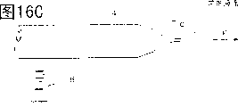
Figure 16 A to 16D shows the unglazed liquid zoomed-in view that nozzle end partly sprays from the delustring equipment of the 17 embodiment.
The specific embodiment
First embodiment
As the schematic construction of a delustring equipment that relates to static filming equipment example of the present invention as depicted in figs. 1 and 2.Fig. 2 shows the front view of a delustring equipment 100 shown in Figure 1.
As depicted in figs. 1 and 2, this delustring equipment 100 that relates to first embodiment has a spray head main body 2, a nozzle plate 6 and a high-voltage DC power supply 8.The shape of this spray head main body 2 is as a hollow cylinder that has a bottom.Nozzle plate 6 is equivalent to the nozzle among the present invention, and it is a disc, and covers the perforate part of this spray head main body 2.Can spray some tubular nozzles 4 these nozzle plates 6 of embedding of unglazed liquid with the drop form, be in line along this nozzle plate direction from top to bottom.High pressure DC power supply 8 applies the DC high pressure to spray head main body 2.The device for generating voltage that high pressure DC power supply 8 is equivalent among the present invention.In delustring equipment 100, a spray head 10 is made of spray head main body 2 and nozzle plate 6.Inside at spray head 10 forms a unglazed fluid cartridge 12 that is equivalent to the plated film fluid cartridge among the present invention and wherein stores this unglazed liquid.Notice that this unglazed liquid is equivalent to the plated film liquid among the present invention.
In this first embodiment, the negative pole of high pressure DC power supply 8 is connected to spray head main body 2, plus earth.So a negative DC high pressure is applied to spray head 10.Yet, the positive pole of high pressure DC power supply 8 is connected to the part of spray head 10, with minus earth, also can apply a positive DC high pressure to spray head 10.
When a PS plate P was carried out unglazed processing, the position of this PS plate P should make its a plate forming surface P2, promptly formed the surface of photosensitive layer one side, over against the end of nozzle 4.In the example depicted in fig. 1, this PS plate P is the lamella shape that has been cut into preliminary dimension.Yet this PS plate P also can be continuous fillet shape, promptly also can be the lath shape.When this PS plate P was lamella shape shown in Figure 1, this PS plate P was fixed over against nozzle 4.Yet when this PS plate P was the lath shape, this PS plate P preferably transmitted along the direction vertical with nozzle 4 orientation in nozzle plate 6 with constant speed, i.e. the projecting direction of Fig. 1 picture, perhaps opposite with it direction.
Because this PS plate P is aforesaid lamella shape, so as shown in Figure 1, a lead 14 of a ground connection is connected to this PS plate P.If this PS plate P is the lath shape,, and this conductive drum ground connection both can as long as a conductive drum that rolls on the conveyer of this PS plate of transmission P in adjacent this PS plate P, while is provided so.
Spray the process of this unglazed liquid from the end of nozzle 4 and see Fig. 3 A to Fig. 3 C.
The drop that Fig. 4 represents unglazed liquid is the relation between L and the V during from nozzle 4 terminal injections, and wherein L is nozzle 4 terminal distances to this PS plate P, and V is the absolute value of voltage that high pressure DC power supply 8 is applied to spray head main body 2.
The scope of the zone of drawing shade among Fig. 4 L that is unglazed liquid charged drop when nozzle 4 sprays and V.In this scope, the absolute value of voltage V is big more, and atomizing frequency Hz (i.e. the quantity of this unglazed liquid charged drop that sprays in the second) is just high more.Yet, when the absolute value of voltage V becomes when exceeding Fig. 4 shade scope, the uneven situation of charged drop diameter that nozzle 4 sprays will appear.So voltage V preferably has the absolute value in Fig. 4 scope.
In relating to the delustring equipment 100 of this first embodiment, the unglazed liquid charged drop that nozzle 4 sprays has particle size highly uniformly, and has very the particle size distribution near monodispersity.And, according to delustring equipment 100, can spray full-bodied unglazed liquid.
Therefore, according to delustring equipment 100, can on the P2 of the plate forming of this PS plate P surface, generate diameter and highly even, with regard to its diameter a bigger unglazed aspect of its aspect ratio.
Second embodiment
Be included in a delustring equipment within the static filming equipment of the present invention another example structural representation as shown in Figure 5.In Fig. 5, use with Fig. 1 to Fig. 3 C among the element of identical reference number representation and Fig. 1 to Fig. 3 C element with these reference number representation identical.
As shown in Figure 5, a delustring equipment 102 that relates to this second embodiment is identical with delustring equipment 100 structures that relate to this first embodiment, but different is, a nozzle plate 62 of installing on the spray head 20 is a kind of structures that form nozzle bore 42 on a rosette, they are through holes, edge direction from top to bottom is in line, and sees Fig. 5.
In delustring equipment 102, the charged drop of this unglazed liquid sprays from nozzle bore 42.
Except the characteristics of delustring equipment 100 with first embodiment, the characteristics of delustring equipment 102 are, because just can make nozzle plate 62 as long as form nozzle bore 42 on a rosette, so the manufacturing of nozzle plate 62 is just very cheap.
The 3rd embodiment
The schematic construction of an example of the delustring equipment of a voltage application electrode of installation is seen Fig. 6 in spray head.In Fig. 6, use with Fig. 1 to Fig. 3 C among the element of identical reference number representation and Fig. 1 to Fig. 3 C element with these reference number representation identical.
As shown in Figure 6, a delustring equipment 104 that relates to the 3rd embodiment is identical with delustring equipment 100 structures that relate to first embodiment, different is, a plate shaped voltage application electrode 16 that is parallel to nozzle plate 6 is provided in spray head main body 2, and this voltage application electrode 16 is connected to the negative pole of high pressure DC power supply 8.Notice that voltage application electrode 16 also can be connected to the positive pole of high pressure DC power supply 8.
The negative DC high pressure that high pressure DC power supply 8 applies is applied to the unglazed liquid of storing in the unglazed fluid cartridge in the spray head 10 by voltage application electrode 16.And, apply electric field of generation between electrode 16 and this PS plate P at power supply.Therefore, described in first embodiment, at the end of nozzle 4, this is unglazed, and liquid forms a taper meniscus, and this meniscus is pulled out and leave the end of nozzle 4 by the Coulomb force, thereby produces a spherical charged drop.
In delustring equipment 104, the DC high pressure is applied to this unglazed liquid by voltage application electrode 16.Thereby delustring equipment 104 not only has the characteristics identical with the delustring equipment 100 of first embodiment, and spray head main body 2, nozzle plate 6 and nozzle 4 can make with certain insulating materials, for example with certain plastics or the manufacturing of certain insulating ceramics.Therefore, delustring equipment 104 is also preferably considered spray head main body 2, nozzle plate 6 and nozzle 4 are made an integral body.
The 4th embodiment
The schematic construction of another example of the delustring equipment of a voltage application electrode of installation is seen Fig. 7 in spray head.In Fig. 7, use with Fig. 1 to Fig. 3 C among the element of identical reference number representation and Fig. 1 to Fig. 3 C element with these reference number representation identical.
As shown in Figure 7, a delustring equipment 106 that relates to the 4th embodiment is identical with delustring equipment 102 structures that relate to second embodiment, different is, in spray head main body 2, have the plate shaped voltage application electrode 16 parallel, and voltage application electrode 16 is connected to the negative pole of DC high voltage source 8 with nozzle plate 62.Notice that voltage application electrode 16 also can be connected to the positive pole of high pressure DC power supply 8.
The 5th embodiment
The schematic construction of an example that has the delustring equipment of a unglazed fluid cartridge voltage bringing device is seen Fig. 8.In Fig. 8, use with Fig. 1 to Fig. 3 C among the element of identical reference number representation and Fig. 1 to Fig. 3 C element with these reference number representation identical.
As shown in Figure 8, it is discoid and cover the nozzle 24 of spray head 20 perforates part and perforate side head part that covers spray head main body 20 and nozzle plate locking cap 22 that can fixed nozzle plate 24 that a delustring equipment 108 that relates to the 5th embodiment has a spray head main body that is shaped as a band end hollow cylinder 20, one.In Fig. 8, nozzle bore 26 is in line on nozzle plate 24 from top to bottom.Middle body at nozzle plate locking cap 22 has a perforate part 22A, and after nozzle plate 24 was loaded onto, it made outside this part that has nozzle bore 26 on the nozzle plate 24 is exposed to.The marginal portion of perforate 22A is cut into the inclined-plane laterally.
A spray head 30 is made of spray head main body 20, nozzle plate 24 and nozzle plate locking cap 22.
A cylinder-piston 32 is positioned in the space that is surrounded by spray head main body 20 and nozzle plate 24.A piezoelectric element 34 that back and forth promotes piston 32 at direction and rightabout towards nozzle plate 24 is arranged between the bottom surface of piston 32 and spray head main body 20.Piezoelectric element 34 is connected to a waveform generator (draw), and it applies one towards stretching with the fixed cycle with nozzle plate 24 dorsad and shrinking the driving signal of this piezoelectric element.
A hollow cylinder sealing gasket 36 is fixed between the side and spray head main body 20 interior sidewall surface of piston 32.Hollow cylinder sealing gasket 36 usefulness retractable material (such as silicon rubber etc.) are made, and it can prevent that this unglazed liquid is from leakage between the side of piston 32 and the spray head main body 20.Hollow cylinder sealing gasket 36 also plays a director element, and guiding piston 32 moves along convergence and the direction of leaving nozzle plate 24.
Spray head main body 20 is connected to the negative pole of high pressure DC power supply 8, the plus earth of high pressure DC power supply 8.Perhaps opposite, the positive pole of high pressure DC power supply 8 can be connected to spray head main body 20, minus earth.A unglazed fluid cartridge 28 is made of piston 32, spray head main body 20, nozzle plate 24 and hollow cylinder sealing gasket 36.
Note, pass through its unglazed liquid service duct with reference to one of digital 38 expression among Fig. 8 to the unglazed liquid of unglazed fluid cartridge 28 supplies.
When DC high pressure V was applied to spray head main body 20, the charged drop of this unglazed liquid just sprayed to PS plate P with fixing cycle period Hz (fixed cycle) from nozzle bore 26.Applying a driving signal to piezoelectric element 34 synchronously with this cycle H z stretches and systolic pressure electric device 34, thereby driven plunger 32 just can further be strengthened the power of spraying this unglazed liquid from nozzle bore 26 so that exert pressure to unglazed fluid cartridge 28 periodically.
In delustring equipment 108, because it is not powerful to spray the Z-TEK of this unglazed liquid, so can spray the extra high unglazed liquid of viscosity.Therefore, come a PS plate or similar object are carried out unglazed processing by spraying the unglazed liquid of high viscosity, just can form with regard to the bigger unglazed aspect of aspect ratio with regard to its diameter with delustring equipment 108.
Example 1
The plate forming surface of a PS plate adopts the delustring equipment 100 with structure shown in Figure 1 to carry out unglazed processing.
In delustring equipment 100,31 internal diameters are that 50 μ m, length are that the tubular nozzle 4 of 1000 μ m is in line to be embedded in the stainless steel disk that diameter is 70mm with the interval of 1000 μ m and makes nozzle plate 6.The perforate part of the spray head main body 2 that this nozzle plate 6 is fixed to the open circles tubular, the end is arranged, internal diameter is 60mm just constitutes spray head 10.
The positive pole of DC high voltage source 8 is connected to spray head main body 2.The minus earth of DC high voltage source 8.
Shown in Fig. 9 A and Fig. 9 B, the structure with following parts is used as aluminium strip conveyer 300: be placed in aluminium strip W direction of transfer upstream-side-end, transmit conveying roller A2 and the A4 of this aluminium strip W along direction of transfer a; Be placed in direction of transfer a end of downstream side, transmit conveying roller B2 and the B4 of aluminium strip W along direction of transfer a with conveying roller A2 and A4 collaborative work; Between conveying roller A2 and the conveying roller B2, from below the idler pulley C of supporting aluminium strip W; One near conveying roller B2 and the B4, to carrying out dry hot-air drying device D through the aluminium strip after the spray head 10 unglazed processing.
Shown in Fig. 9 A, spray head 10 is fixed between conveying roller A4 and the heated-air drying equipment D, and in as this aluminium strip conveyer 300 this aluminium strip W transmit passage transmission plane T above, thereby make the terminal perforate part of nozzle 4 with the spacing of 50mm over against this transmission plane T, make that simultaneously the orientation of nozzle 4 is vertical with the direction of transfer a of this aluminium strip W.
The metal roller of ground connection is used as idler pulley C.
In aluminium strip conveyer 300, this aluminium strip W is transmitted with the speed of 10m/min.
Become the solution filling to be used as this unglazed liquid in spray head 10 in 25% water of certain copolymer of 100cc, this copolymer is generated than copolymerization by the charge weitght of methyl methacrylate/second diluted acid ethyl ester/acrylic acid sodium with 68: 20: 12.DC high voltage source 8 applies+electric current of 6kV.It is 120mPas (25 ℃) that this unglazed liquid water becomes the viscosity of solution.
This aluminium strip W on the width of a 30mm by unglazed processing.Test under microscope this by the lath W of unglazed processing, can find, with uniform density formed a size evenly, with regard to its bottom surface diameter the bigger spherical unglazed aspect of its aspect ratio.The result is as shown in table 1.
Table 1
| Unglazed liquid | Unglazed aspect | Explanation | |||
| Polymer concentration (percentage by weight) | Viscosity (mPas) | Average diameter (μ m) | Average height (μ m) | ||
| Example 1 | ?25 | ?120 | ?60 | 11 | |
| Comparative example 1 | ?25 | ?120 | ?- | - | Spray difficulty |
| Comparative example 3 | ?13 | ?25 | ?150 | 4 | |
Comparative example 1
Without the spray head in the example 1 10,, the ink gun 200 shown in Figure 10 A and Figure 10 B carries out unglazed processing to aluminium strip W and being fixed to the aluminium strip conveyer 300 shown in Fig. 9 A and Fig. 9 B.Figure 10 A be one along the axial profile of ink gun 200.Figure 10 B represents the Facad structure figure that ink gun 200 is observed from a nozzle plate U described hereinafter.
Shown in Figure 10 A and Figure 10 B, ink gun 200 is equipped with the disc nozzle plate U that has 12 nozzle U2 on it, with the corresponding spraying plating fluid cartridge of each nozzle U2 S, in spraying plating fluid cartridge S and can apply the piezoelectric element T2 that voltage makes this spraying plating liquid spray from nozzle bore U2 to this spraying plating liquid at once.The aperture of nozzle bore U2 is 40 μ m.And, use the spraying plating liquid identical as this spraying plating liquid with example 1.
The results are shown in Table 1.As shown in table 1, be difficult to spray this spraying plating liquid, can't carry out unglazed processing to this aluminium strip W.
Comparative example 2
The process of carrying out the unglazed processing of aluminium strip W is identical with comparative example 1, but 13% of copolymer water becomes solution as this spraying plating liquid in the employing example 1.
The result is as shown in table 1.
Although this spraying plating liquid can be injected, when the drop of this spraying plating liquid adhered to this aluminium strip W, this drop too spread, and can not form a unglazed aspect that certain enough height is arranged.
The 6th embodiment
Structural representation as a delustring equipment 100A who relates to an example of static filming equipment of the present invention is similar to the delustring equipment 100 of first embodiment.The parts identical with delustring equipment 100 are with identical reference number representation, and it illustrates omission.
As shown in figure 11, the end surface 4A of nozzle 4 is perpendicular to the axis of nozzle 4.
For instance, in the metallic plate of predetermined thickness, on thickness direction, make through hole 6A and just can constitute nozzle plate 6 with predetermined interval.And as shown in figure 11, nozzle 4 is embedded nozzle plate 6 can constitute spray head 10.For nozzle 4 is embedded nozzle plates 6, as example, nozzle 4 can be press fitted into through hole 6A, and perhaps nozzle 4 can be mounted to through hole 6A and be fixed therein with suitable method (such as soldering or the like).If nozzle 4 is not embedded nozzle plate 6, nozzle 4 and nozzle plate 6 image patterns 12 can be made an integral body like that yet.For instance, comprise that the method for following process can be used as the method for unitary construction nozzle 4 and nozzle plate 6:
(a) two faces to a silicon wafer carry out spraying plating formation silicon nitride layer;
(b) on this silicon nitride layer, cover aluminium lamination, then this silicon wafer is penetrated etching, make wherein to form perforation;
(c) on the through-hole wall that step (b) forms, form silicon dioxide layer;
(d) silicon nitride and the silicon on this silicon wafer of etching optionally only makes this silicon wafer be thinned to preset thickness and forms nozzle plate 6 that simultaneously, the silica capillary protrudes and forms nozzle 4.
Interior diameter at nozzle 4 is very little, be approximately under the situation of 0.01mm (10 μ m), preferably nozzle 4 and nozzle plate 6 is configured to one.
An inner diameter d at the surperficial endways 4A of nozzle 4 place
2Be preferably within 0.01 to the 0.2mm scope, first-selected especially is within 0.03 to 0.1mm scope.But, inner diameter d
2Also can be less than or equal to 0.01mm, perhaps more than or equal to 0.1mm, this depends on the particle size of the charged drop that will spray and the voltage that this voltage application portion branch applies.
An outside diameter d at the surperficial endways 4A of nozzle 4 place
1It is inner diameter d
23.5 times or below, inner diameter d preferably
21.2 to 3.5 times, first-selected especially is inner diameter d
21.5 to 2.5 times.
If outside diameter d
1It is inner diameter d
23.5 times or below, the drop of this spraying plating liquid just can too not spread at the end surface 4A place of nozzle 4 so.So, even under the situation that a large amount of spraying plating liquid spray from nozzle 4, also can prevent to form excessive charged drop, and prevent that the diameter of this unglazed aspect from becoming inhomogeneous.
If outside diameter d
1It is inner diameter d
21.2 times or more than, even so under the little situation of nozzle 4 external diameters the manufacturing of mouth spray 4 also be easy to.
Can suitably determine with the size of the unglazed aspect that will form according to the voltage that high pressure DC power supply 8 applies to the distance L of this PS plate P from the end surface 4A of nozzle 4 on this PS plate P surface.
This spraying plating liquid from the course of injection of nozzle 4 ends shown in Figure 13 A to Figure 13 D.
Because nozzle 4 is electrically connected to nozzle plate 6 and spray head main body 2, also be applied to nozzle 4 so be applied to the voltage that voltage magnitude is identical on the spray head main body 2 with high pressure DC power supply 8 negative poles.Therefore, the electric field F towards this PS plate P appears, promptly towards right-hand electric field of Figure 13 A to Figure 13 D between nozzle 4 end portion and this PS plate P.Therefore as shown in FIG. 13A, at the end of nozzle 4, this unglazed liquid is pulled to right-hand by this electric field F and forms a taper meniscus Tc who is called as taylor cone.
Because this electric field F acts on meniscus Tc, shown in Figure 13 B, this meniscus Tc is pulled to this PS plate P by the end surface 4A from nozzle 4, and simultaneously, its diffusion also covers whole end surface 4A.So the bottom surface diameter of this meniscus Tc equals the diameter of end surface 4A.
Shown in Figure 13 C, this meniscus Tc is further attracted to this PS plate, and its end portion expand into a ball, thereby forms a charged drop.Simultaneously, a neck appears between this charged drop and this meniscus Tc.
Shown in Figure 13 D, this charged drop separates from the end of this meniscus Tc, flies to this PS plate P then.
Here Figure 13 C is clear shows, big if the bottom surface diameter of this meniscus Tc becomes, the height of this meniscus Tc also becomes greatly so, also becomes big in the terminal charged drop size that forms of this meniscus Tc.
Yet as previously mentioned, in delustring equipment 100A, the outside diameter d of nozzle 4
1It is inner diameter d
23.5 times or below.So the bottom surface diameter of this meniscus Tc also is an inner diameter d
23.5 times or below.
Therefore under the state shown in Figure 13 C, can not form one at the end of this meniscus Tc and have very large diameter charged drop.
In relating to the delustring equipment 100A of the 6th embodiment, can not form at nozzle 4 places and to have very large diameter charged drop.So the particle size of this charged drop is that the particle size distribution of this charged drop is very near monodispersity uniformly.And, even the unglazed liquid of high viscosity also can be injected.
Therefore, according to delustring equipment 100A, can the plate forming of this PS plate P surface P2 form diameter and highly even, with regard to its diameter the bigger unglazed aspect of aspect ratio.
The 7th embodiment
The end that hereinafter is described in nozzle forms the diminish example of a delustring equipment of part of diameter.
The overall structure that relates to the delustring equipment 100B of the 7th embodiment is similar to the delustring equipment 100A of the 6th embodiment, and its structure is seen Fig. 1 and Fig. 2.
The end portion of the nozzle 4 of delustring equipment 100B and the adjacent domain of this end portion are seen Figure 14.
As shown in figure 14, the end portion diameter at nozzle 4 peripheral surface 4a places reduces, and makes this end portion become tapered shape, i.e. a cone shape.At the end of nozzle 4, peripheral surface 4a intersects to enclose surperficial 4b in angle θ and the nozzle 4.
Angle θ is an acute angle less than 90 °.From mechanical machining angle, angle θ be preferably 10 ° or more than, Shou Xuan angle is 30 ° to 75 ° especially.
Another example of nozzle 4 is seen Figure 15 A and Figure 15 B.Figure 15 A represents that the diameter of the nozzle part that diminishes is an example of the curved surface that outwards protrudes, and Figure 15 B represents the diameter of the nozzle example of part for inwardly recessed curved surface that diminish.In two kinds of nozzles shown in Figure 15 A and Figure 15 B, angle θ all be peripheral surface 4a and in enclose the angle that surperficial 4b intersects.
This unglazed liquid is seen Figure 16 A to Figure 16 D from the process of the end injection of nozzle 4.
Shown in Figure 16 A, also the same with delustring equipment 100A in delustring equipment 100B, this unglazed liquid is pulled out to the right by electric field F at the end of nozzle 4, and forms a taper meniscus Tc who is called as taylor cone.
Shown in Figure 16 B, this taper meniscus Tc is pulled to this PS plate P by electric field F.
Shown in Figure 16 C, the end of this meniscus Tc expand into charged drop of spherical formation.Simultaneously, between this charged drop and this meniscus Tc, form a neck.Shown in Figure 16 D, this charged drop separates and flies to this PS plate P from the end of this meniscus Tc.
Yet as mentioned above, at the end of nozzle 4, peripheral surface 4a with in enclose surperficial 4b and intersect with an acute angle.So, peripheral surface 4a with in enclose surperficial 4b and just constituted a carinate bead.
Therefore, even because the voltage method that adopts raising high pressure DC power supply 8 or similar device to apply increases the unglazed amount of fluid of spraying from nozzle 4, this meniscus Tc of Xing Chenging can be to external diffusion yet endways, and can not form one and have too large diameter drop.So the particle size of this charged drop is very even.And, even also can spray for full-bodied unglazed liquid.
Therefore, according to delustring equipment 100B, can the plate forming of this PS plate P surface P2 form diameter and highly even, with regard to its diameter the bigger unglazed aspect of its aspect ratio.
(example 2 is to example 4, comparative example 3)
Unglazed processing is carried out with the delustring equipment 100A that relates to the 6th embodiment in the plate forming surface of a PS plate.
In delustring equipment 100A, 31 terminal internal diameters be 0.1mm, external diameter to be 0.15 to 0.40mm tubular nozzle 4 with the interval of 1000 μ m be in line embeds the stainless steel disk of diameter 70mm, constitute nozzle plate 6.This nozzle plate 6 is fixed to the perforate of spray head main body 2 and partly makes spray head 10, spray head main body 2 for have at the bottom of one, internal diameter is the hollow cylinder of 60mm.The external diameter of nozzle 4 is as shown in table 2.
The positive pole of DC high voltage source 8 is connected to spray head main body 2.The minus earth of DC high voltage source 8.
A device that is similar to aluminium strip conveyer 300 shown in Fig. 9 A and Fig. 9 B is used as this PS substrate transfer device.In other words, the structure that has as lower member is used as this PS substrate transfer device: be positioned at upstream one side end of this PS plate P (" W " shown in Fig. 9 A and Fig. 9 B) direction of transfer, transmit conveying roller A2 and the A4 of this PS plate P along direction of transfer a; Be positioned at direction of transfer a downstream one side end, transmit conveying roller B2 and the B4 of this PS plate P along direction of transfer a with conveying roller A2 and A4 collaborative work; Between conveying roller A2 and conveying roller B2, from descending the idler pulley C of this PS plate of surface bearing P; Near conveying roller B2 and B4, this PS plate P that carries out unglazed processing by spray head 10 is carried out dry hot-air drying device D.
This PS plate P transmits on this PS substrate transfer device with the speed of 10m/min.
This PS plate P is carried out unglazed processing on the width of 30mm.Can find when the PS plate P of the unglazed processing of this process of test under microscope, formed a hemispherical unglazed aspect with uniform density in example 2 and example 3, its size is even, and aspect ratio is bigger with regard to its bottom surface diameter.And find that in example 4 being distributed with of this unglazed aspect is inhomogeneous slightly.The result is as shown in table 2.
Table 2
| Internal diameter | External diameter | External diameter/internal diameter | Unglazed aspect diameter | Unglazed deck structure | Other | |
| Example 2 | ? ? ? ? ? ? ? ? ?0.1mm | ?0.15mm | ?1.5 | ?60-80μm | ○ | |
| Example 3 | ?0.20mm | ?2.0 | ?70-100μm | ○ | ||
| Example 4 | ?0.30mm | ?3.0 | ?60-350μm | △ | Particle size distribution is inhomogeneous slightly | |
| Comparative example 3 | ?0.40mm | ?4.0 | ?- | × | Can't form particulate |
(example 5 is to example 9)
Unglazed processing is carried out with the delustring equipment 100B that relates to the 7th embodiment in the plate forming surface of a PS plate.
The process manufacturing that spray head 10 usefulness and example 2 are identical, but adopt nozzle shown in Figure 14.This spray head 10 is installed to a PS substrate transfer device identical with example 2, and carries out the unglazed processing procedure to this PS plate P.
When the end periphery of nozzle 4 surface and in enclose the angle θ that intersects between the surface when between 90 °, changing for 15 °, the relation of angle θ and unglazed aspect diameter is as shown in table 3.
Table 3
| Internal diameter | External diameter | Angle θ (°) | Unglazed aspect diameter | |
| Example 5 | ? ? 0.10mm | ? ? 0.15mm | ?90 | ?70-100μm |
| Example 6 | ?75 | ?60-80μm | ||
| Example 7 | ?45 | ?60-80μm | ||
| Example 8 | ?30 | ?60-80μm | ||
| Example 9 | ?15 | ?45-75μm |
As seen from Table 3, angle θ hour, unglazed aspect diameter was also little.
As mentioned above, the invention provides a static spraying plating equipment and a kind of static method of spray plating, they are simple in structure, can spray certain high viscosity plated film liquid with the drop form with good monodispersity, so can be suitable for the PS plate is carried out unglazed processing.
Claims (39)
1, static filming equipment comprises:
A plated film fluid cartridge, certain plated film liquid of the storage inside of this plated film fluid cartridge;
A voltage application portion branch, its plated film liquid in this plated film fluid cartridge applies voltage, this voltage with respect to will by this plated film liquid of spraying plating by coated body and Yan Weizheng or for negative;
A nozzle, it has been applied the plated film liquid of voltage with the drop form to this by this voltage application portion branch by the coated body spraying plating.
2, the static filming equipment that meets claim 1, wherein this equipment has one group of a plurality of nozzle.
3, the static filming equipment that meets claim 1, wherein this nozzle is a tubular nozzle that passes this plated film fluid cartridge wall.
4, the static filming equipment that meets claim 1, wherein this nozzle is a nozzle bore that passes this plated film fluid cartridge wall.
5, the static filming equipment that meets claim 1, wherein this voltage application portion branch is a device for generating voltage that is connected among this plated film fluid cartridge and this nozzle at least one.
6, the static filming equipment that meets claim 1, wherein this voltage application portion branch be one be installed in this plated film fluid cartridge, voltage application electrode that the plated film liquid in this plated film fluid cartridge applies voltage.
7, the static filming equipment that meets claim 1, wherein the voltage that is applied by this voltage application portion branch is a dc voltage.
8, the static filming equipment that meets claim 1 should be a kind of continuous fillet shape by coated body wherein.
9, the static filming equipment that meets claim 1, it also comprise one when this is sprayed this plated film liquid by coated body, will be somebody's turn to do by coated body ground connection by the coated body grounded part.
10, the static filming equipment that meets claim 9, should be an earth electrode that is grounded when this plated film liquid of spraying plating wherein by the coated body grounded part, it is installed in this by between plated film fluid cartridge and this nozzle, perhaps be close to this by a surface of plated film liquid, this place, surface one side is opposite with a side that will adhere to this plated film liquid.
11, the static filming equipment that meets claim 1, wherein this plated film fluid cartridge has a plated film fluid cartridge pressures partially, and it was exerted pressure to the inside of this plated film fluid cartridge with the given cycle.
12, the static filming equipment that meets claim 11, wherein this plated film fluid cartridge pressures partially is driven by a piezoelectric element.
13, the static filming equipment that meets claim 1 wherein should be conducted electricity by coated body.
14, the static filming equipment that meets claim 1, wherein should be by coated body be a PS plate, this plated film liquid is a kind of unglazed liquid that this PS plate is tarnished of being used for.
15, the static filming equipment that meets claim 1, wherein the diameter of this nozzle is suitably selected according to the viscosity size of this plated film liquid.
16, the static filming equipment that meets claim 1, wherein the voltage that is applied by this voltage application portion branch is AC voltage.
17, the static filming equipment that meets claim 16, wherein the frequency of this AC voltage is 1000Hz or higher.
18, a kind of electrostatic coating method, it comprises the steps:
Certain plated film liquid in being stored in the plated film fluid cartridge applies voltage, this voltage with respect to will by this plated film liquid of spraying plating by coated body and Yan Weizheng or for negative;
Sprayed this plated film liquid to this by coated body from a nozzle of this plated film fluid cartridge with the drop form.
19, static filming equipment comprises:
A plated film fluid cartridge is held certain plated film liquid in the inside of this plated film fluid cartridge;
A tubular nozzle, it sprays the plated film liquid that is contained in this plated film fluid cartridge;
A voltage application portion branch, it to this plated film liquid apply with respect to will by this plated film liquid of spraying plating by coated body and Yan Weizheng or be negative voltage so that this plated film liquid is sprayed by coated body to this from this nozzle with the form of drop,
Wherein this nozzle an external dimensions of this nozzle end be 3.5 times of an inside diameter or below.
20, the static filming equipment that meets claim 19, wherein this nozzle is 1.2 to 3.5 times of its inside diameter in the external dimensions of this nozzle end part.
21, static filming equipment comprises:
A plated film fluid cartridge is held certain plated film liquid in the inside of this plated film fluid cartridge;
A tubular nozzle, it sprays the plated film liquid that is contained in this plated film fluid cartridge;
A voltage application portion branch, it to this plated film liquid apply with respect to will by this plated film liquid of spraying plating by coated body and Yan Weizheng or be negative voltage so that this plated film liquid is sprayed by coated body to this from this nozzle with the form of drop,
Wherein at the peripheral surface diameter that forms this nozzle on this nozzle in the diameter that on the direction of this nozzle end, the reduces part that diminishes.
22, the static filming equipment that meets claim 21, wherein this diameter diminish the part diameter reduce in the convergent mode.
23, the static filming equipment that meets claim 21, wherein this peripheral surface of this nozzle end with in enclose the angle that intersects on the surface more than or equal to 10 ° and less than 90 °.
24, the static filming equipment that meets claim 19, wherein this nozzle internal diameter is 0.01 to 0.2mm.
25, the static filming equipment that meets claim 19, wherein the length of this nozzle is 0.3 to 25mm.
26, the static filming equipment that meets claim 19, wherein this nozzle is made with certain metal.
27, the static filming equipment that meets claim 19, wherein this equipment has one group of a plurality of nozzle.
28, the static filming equipment that meets claim 19, wherein this nozzle is upright on the plate shaped nozzle plate of a part that constitutes this plated film fluid cartridge wall.
29, the static filming equipment that meets claim 19, wherein this voltage application portion branch is a device for generating voltage that is connected among this plated film fluid cartridge and this nozzle at least one.
30, the static filming equipment that meets claim 19, wherein this voltage application portion branch is a voltage application electrode that is installed in this plated film fluid cartridge, can applies voltage to the plated film liquid in this plated film fluid cartridge.
31, the static filming equipment that meets claim 19, wherein the voltage that is applied by this voltage application portion branch is dc voltage.
32, the static filming equipment that meets claim 19, wherein the voltage that is applied by this voltage application portion branch is AC voltage.
33, the static filming equipment that meets claim 32, wherein the frequency of this AC voltage is 500Hz or higher.
34, the static filming equipment that meets claim 19 wherein should be conducted electricity by coated body.
35, the static filming equipment that meets claim 19 should be a kind of continuous fillet shape by coated body wherein.
36, the static filming equipment that meets claim 34, it also comprise one will be somebody's turn to do during to this by this plated film liquid of coated body spraying plating by coated body ground connection by the coated body grounded part.
37, the static filming equipment that meets claim 19, wherein should be by coated body be a PS plate, this plated film liquid is a kind of unglazed liquid that this PS plate is tarnished of being used for.
38, a kind of electrostatic coating method, it comprises the steps:
Certain plated film liquid that holds in the plated film fluid cartridge applies voltage, this voltage with respect to will by this plated film liquid of spraying plating by coated body and Yan Weizheng or for negative;
Sprayed this plated film liquid to this by coated body from the nozzle on this plated film fluid cartridge with the drop form, the external diameter of the end portion of this nozzle be 3.5 times of internal diameter or below.
39, a kind of electrostatic coating method, it comprises the steps:
The kind plated film liquid that holds in the plated film fluid cartridge applies voltage, this voltage with respect to will by this plated film liquid of spraying plating by coated body and Yan Weizheng or for negative;
Sprayed this plated film liquid to this by coated body from the nozzle on this plated film fluid cartridge with the drop form, its diameter is being arranged on the peripheral surface of this nozzle in the diameter that on end direction of this nozzle, the reduces part that diminishes.
Applications Claiming Priority (4)
| Application Number | Priority Date | Filing Date | Title |
|---|---|---|---|
| JP2001211120A JP2003024835A (en) | 2001-07-11 | 2001-07-11 | Electrostatic coating apparatus and electrostatic coating method |
| JP211120/2001 | 2001-07-11 | ||
| JP27712/2002 | 2002-02-05 | ||
| JP2002027712A JP2003225591A (en) | 2002-02-05 | 2002-02-05 | Electrostatic coating apparatus and electrostatic coating method |
Publications (1)
| Publication Number | Publication Date |
|---|---|
| CN1396005A true CN1396005A (en) | 2003-02-12 |
Family
ID=26618543
Family Applications (1)
| Application Number | Title | Priority Date | Filing Date |
|---|---|---|---|
| CN02140600.6A Pending CN1396005A (en) | 2001-07-11 | 2002-07-10 | Electrostatic film coating equipment and electrostatic film coating method |
Country Status (3)
| Country | Link |
|---|---|
| US (1) | US20030029379A1 (en) |
| EP (1) | EP1275440A1 (en) |
| CN (1) | CN1396005A (en) |
Cited By (9)
| Publication number | Priority date | Publication date | Assignee | Title |
|---|---|---|---|---|
| US7219976B2 (en) | 2004-02-24 | 2007-05-22 | Seiko Epson Corporation | Wiping device, droplet discharge device, electro-optical device, method for manufacturing an electro-optical device, and electronic equipment |
| CN100350556C (en) * | 2004-03-23 | 2007-11-21 | 大日本网目版制造株式会社 | Processing apparatus |
| CN1988963B (en) * | 2004-07-26 | 2010-12-29 | 柯尼卡美能达控股株式会社 | Liquid discharging device |
| CN103736611A (en) * | 2013-12-30 | 2014-04-23 | 吴江市振中纺织品有限公司 | Flexible anti-skid cushion manufacturing device |
| WO2014083782A1 (en) * | 2012-11-30 | 2014-06-05 | アピックヤマダ株式会社 | Resist film forming device and method, conductive film forming and circuit forming device and method, electromagnetic wave shield forming device and method, shortwave high-transmissibility insulation film forming device and method, fluorescent light body film forming device and method, trace material combining device and method, resin molding device, resin molding method, thin film forming device, organic electroluminescence element, bump forming device and method, wiring forming device and method, and wiring structure body |
| CN104994963A (en) * | 2013-02-11 | 2015-10-21 | 杜尔系统有限责任公司 | Perforated plate for an application device and corresponding application and production method |
| CN110325659A (en) * | 2017-02-24 | 2019-10-11 | 杰富意钢铁株式会社 | Continuous hot-dipping metal handling apparatus and the hot-dip plating metal processing method for using the device |
| CN111212692A (en) * | 2017-10-17 | 2020-05-29 | 阿耐思特岩田株式会社 | Electrostatic spraying device |
| CN113941462A (en) * | 2021-11-17 | 2022-01-18 | 秦皇岛泰治医疗科技有限公司 | Be used for gauze mask production photocatalyst spraying equipment |
Families Citing this family (11)
| Publication number | Priority date | Publication date | Assignee | Title |
|---|---|---|---|---|
| JP3956222B2 (en) | 2002-09-24 | 2007-08-08 | コニカミノルタホールディングス株式会社 | Liquid ejection device |
| EP1550556B1 (en) | 2002-09-24 | 2010-02-24 | Konica Minolta Holdings, Inc. | Method for manufacturing electrostatic attraction type liquid discharge head, method for manufacturing nozzle plate. |
| JP2004136652A (en) * | 2002-09-24 | 2004-05-13 | Konica Minolta Holdings Inc | Liquid ejector |
| JP4489649B2 (en) * | 2005-07-20 | 2010-06-23 | シャープ株式会社 | Inkjet head manufacturing method |
| JP2009066806A (en) * | 2007-09-11 | 2009-04-02 | Seiko Epson Corp | Liquid discharging apparatus and its control method |
| DE102008053178A1 (en) | 2008-10-24 | 2010-05-12 | Dürr Systems GmbH | Coating device and associated coating method |
| DE102009020415B4 (en) * | 2009-05-08 | 2016-04-28 | Fraunhofer-Gesellschaft zur Förderung der angewandten Forschung e.V. | Electrostatic coating process and electrostatic coating device |
| JP5903769B2 (en) * | 2011-03-29 | 2016-04-13 | セイコーエプソン株式会社 | Liquid ejecting head and liquid ejecting apparatus |
| JP6228949B2 (en) * | 2015-06-08 | 2017-11-08 | 矢崎総業株式会社 | Coating apparatus and coating method |
| DE102016000356A1 (en) * | 2016-01-14 | 2017-07-20 | Dürr Systems Ag | Perforated plate with reduced diameter in one or both edge regions of a row of nozzles |
| DE102016000390A1 (en) | 2016-01-14 | 2017-07-20 | Dürr Systems Ag | Perforated plate with increased hole spacing in one or both edge regions of a row of nozzles |
Family Cites Families (11)
| Publication number | Priority date | Publication date | Assignee | Title |
|---|---|---|---|---|
| FR1117341A (en) * | 1950-10-13 | 1956-05-22 | Device for conveying a liquid on a surface, and machine for varnishing or coating the interior of the receptacles, comprising this device | |
| US4263601A (en) * | 1977-10-01 | 1981-04-21 | Canon Kabushiki Kaisha | Image forming process |
| US4349830A (en) * | 1980-11-12 | 1982-09-14 | Burroughs Corporation | Conical nozzle for an electrostatic ink jet printer |
| US4571597A (en) * | 1983-04-21 | 1986-02-18 | Burroughs Corp. | Electrostatic ink jet system with potential barrier aperture |
| DE3620406A1 (en) * | 1986-06-18 | 1987-12-23 | Ernest Avgustinovic Druzinin | Device for applying thin-film coatings to products by means of electrostatic spraying |
| GB8826357D0 (en) * | 1988-11-10 | 1988-12-14 | Ici Plc | Atomisation of liquids |
| DE3925539A1 (en) * | 1989-08-02 | 1991-02-07 | Hoechst Ag | METHOD AND DEVICE FOR COATING A LAYER |
| JP2768080B2 (en) * | 1990-11-28 | 1998-06-25 | 松下電器産業株式会社 | Ink jet recording device |
| GB9514335D0 (en) * | 1995-07-13 | 1995-09-13 | The Technology Partnership Plc | Solids and liquids supply |
| US5923346A (en) * | 1995-10-23 | 1999-07-13 | Imaging Technology International | Shadow pulse compensation of an ink jet printer |
| US5873523A (en) * | 1996-02-29 | 1999-02-23 | Yale University | Electrospray employing corona-assisted cone-jet mode |
-
2002
- 2002-07-09 EP EP02015280A patent/EP1275440A1/en not_active Withdrawn
- 2002-07-09 US US10/190,836 patent/US20030029379A1/en not_active Abandoned
- 2002-07-10 CN CN02140600.6A patent/CN1396005A/en active Pending
Cited By (13)
| Publication number | Priority date | Publication date | Assignee | Title |
|---|---|---|---|---|
| CN100377881C (en) * | 2004-02-24 | 2008-04-02 | 精工爱普生株式会社 | Wiping device, droplet discharge device, electro-optical device, method for manufacturing an electro-optical device, and electronic equipment |
| US7219976B2 (en) | 2004-02-24 | 2007-05-22 | Seiko Epson Corporation | Wiping device, droplet discharge device, electro-optical device, method for manufacturing an electro-optical device, and electronic equipment |
| CN100350556C (en) * | 2004-03-23 | 2007-11-21 | 大日本网目版制造株式会社 | Processing apparatus |
| CN1988963B (en) * | 2004-07-26 | 2010-12-29 | 柯尼卡美能达控股株式会社 | Liquid discharging device |
| WO2014083782A1 (en) * | 2012-11-30 | 2014-06-05 | アピックヤマダ株式会社 | Resist film forming device and method, conductive film forming and circuit forming device and method, electromagnetic wave shield forming device and method, shortwave high-transmissibility insulation film forming device and method, fluorescent light body film forming device and method, trace material combining device and method, resin molding device, resin molding method, thin film forming device, organic electroluminescence element, bump forming device and method, wiring forming device and method, and wiring structure body |
| CN104994963A (en) * | 2013-02-11 | 2015-10-21 | 杜尔系统有限责任公司 | Perforated plate for an application device and corresponding application and production method |
| US10232400B2 (en) | 2013-02-11 | 2019-03-19 | Durr Systems Gmbh | Perforated plate for an application device and corresponding method |
| CN104994963B (en) * | 2013-02-11 | 2019-06-11 | 杜尔系统有限责任公司 | For the perforated plate of applicator device and corresponding application and manufacturing method |
| CN103736611A (en) * | 2013-12-30 | 2014-04-23 | 吴江市振中纺织品有限公司 | Flexible anti-skid cushion manufacturing device |
| CN110325659A (en) * | 2017-02-24 | 2019-10-11 | 杰富意钢铁株式会社 | Continuous hot-dipping metal handling apparatus and the hot-dip plating metal processing method for using the device |
| US11162166B2 (en) | 2017-02-24 | 2021-11-02 | Jfe Steel Corporation | Apparatus for continuous molten metal coating treatment and method for molten metal coating treatment using same |
| CN111212692A (en) * | 2017-10-17 | 2020-05-29 | 阿耐思特岩田株式会社 | Electrostatic spraying device |
| CN113941462A (en) * | 2021-11-17 | 2022-01-18 | 秦皇岛泰治医疗科技有限公司 | Be used for gauze mask production photocatalyst spraying equipment |
Also Published As
| Publication number | Publication date |
|---|---|
| EP1275440A1 (en) | 2003-01-15 |
| US20030029379A1 (en) | 2003-02-13 |
Similar Documents
| Publication | Publication Date | Title |
|---|---|---|
| CN1396005A (en) | Electrostatic film coating equipment and electrostatic film coating method | |
| CN1165208C (en) | Plasma processing apparatus and method | |
| CN1684834A (en) | Method for manufacturing electrostatic attraction type liquid discharge head, method for manufacturing nozzle plate, method for driving electrostatic attraction type liquid discharge head, electrostat | |
| CN1286349C (en) | Plasma processing device and plasma processing method | |
| CN1194328C (en) | Method and device for forming picture on base plate | |
| CN1635933A (en) | Ultrafine fluid jet apparatus | |
| CN1207107C (en) | Powder coating process | |
| CN1410265A (en) | Liquid spraying head driving method and driving device thereof | |
| CN1310759C (en) | Drop ejection device, printing device, printing meethod and electrooptics device | |
| CN1684832A (en) | Liquid jetting device | |
| CN1540738A (en) | Plasma treatment appts. focusing ring and base | |
| CN1500561A (en) | Fluid discharge device and discharge method | |
| CN1057349C (en) | Plasma processing method and plasma processing apparatus | |
| CN1089120C (en) | Plating method | |
| CN1265684C (en) | Atmospheric plasma method for treating electricity conducting materials and device therefor | |
| CN1170664A (en) | Method for discharging liquid by communicating bubble with atmosphere, and apparatus | |
| CN1066386C (en) | Apparatus and method for forming films | |
| CN1726095A (en) | Powder coating apparatus and process | |
| CN1551279A (en) | Fluid coating device,fluid coating method and plasma display panel | |
| CN1684833A (en) | Liquid jetting device | |
| CN1519113A (en) | Ink-jet head, and recording device using same | |
| CN1530176A (en) | Placode processor and liquid feeder | |
| CN1823554A (en) | Plasma processing apparatus and method for producing same | |
| CN1832810A (en) | Electrostatic suction type fluid discharge device, electrostatic suction type fluid discharge method, and plot pattern formation method using the same | |
| CN1778004A (en) | Fuel cell |
Legal Events
| Date | Code | Title | Description |
|---|---|---|---|
| C06 | Publication | ||
| PB01 | Publication | ||
| C10 | Entry into substantive examination | ||
| SE01 | Entry into force of request for substantive examination | ||
| C02 | Deemed withdrawal of patent application after publication (patent law 2001) | ||
| WD01 | Invention patent application deemed withdrawn after publication |