CN1288335C - Dual fuel engine - Google Patents
Dual fuel engine Download PDFInfo
- Publication number
- CN1288335C CN1288335C CNB018230156A CN01823015A CN1288335C CN 1288335 C CN1288335 C CN 1288335C CN B018230156 A CNB018230156 A CN B018230156A CN 01823015 A CN01823015 A CN 01823015A CN 1288335 C CN1288335 C CN 1288335C
- Authority
- CN
- China
- Prior art keywords
- mentioned
- valve
- compression ratio
- fuel
- gas
- Prior art date
- Legal status (The legal status is an assumption and is not a legal conclusion. Google has not performed a legal analysis and makes no representation as to the accuracy of the status listed.)
- Expired - Lifetime
Links
Images


Classifications
-
- F—MECHANICAL ENGINEERING; LIGHTING; HEATING; WEAPONS; BLASTING
- F02—COMBUSTION ENGINES; HOT-GAS OR COMBUSTION-PRODUCT ENGINE PLANTS
- F02M—SUPPLYING COMBUSTION ENGINES IN GENERAL WITH COMBUSTIBLE MIXTURES OR CONSTITUENTS THEREOF
- F02M17/00—Carburettors having pertinent characteristics not provided for in, or of interest apart from, the apparatus of preceding main groups F02M1/00 - F02M15/00
- F02M17/18—Other surface carburettors
- F02M17/20—Other surface carburettors with fuel bath
- F02M17/22—Other surface carburettors with fuel bath with air bubbling through bath
-
- F—MECHANICAL ENGINEERING; LIGHTING; HEATING; WEAPONS; BLASTING
- F02—COMBUSTION ENGINES; HOT-GAS OR COMBUSTION-PRODUCT ENGINE PLANTS
- F02D—CONTROLLING COMBUSTION ENGINES
- F02D19/00—Controlling engines characterised by their use of non-liquid fuels, pluralities of fuels, or non-fuel substances added to the combustible mixtures
- F02D19/06—Controlling engines characterised by their use of non-liquid fuels, pluralities of fuels, or non-fuel substances added to the combustible mixtures peculiar to engines working with pluralities of fuels, e.g. alternatively with light and heavy fuel oil, other than engines indifferent to the fuel consumed
-
- F—MECHANICAL ENGINEERING; LIGHTING; HEATING; WEAPONS; BLASTING
- F02—COMBUSTION ENGINES; HOT-GAS OR COMBUSTION-PRODUCT ENGINE PLANTS
- F02B—INTERNAL-COMBUSTION PISTON ENGINES; COMBUSTION ENGINES IN GENERAL
- F02B19/00—Engines characterised by precombustion chambers
- F02B19/10—Engines characterised by precombustion chambers with fuel introduced partly into pre-combustion chamber, and partly into cylinder
- F02B19/1019—Engines characterised by precombustion chambers with fuel introduced partly into pre-combustion chamber, and partly into cylinder with only one pre-combustion chamber
- F02B19/108—Engines characterised by precombustion chambers with fuel introduced partly into pre-combustion chamber, and partly into cylinder with only one pre-combustion chamber with fuel injection at least into pre-combustion chamber, i.e. injector mounted directly in the pre-combustion chamber
-
- F—MECHANICAL ENGINEERING; LIGHTING; HEATING; WEAPONS; BLASTING
- F02—COMBUSTION ENGINES; HOT-GAS OR COMBUSTION-PRODUCT ENGINE PLANTS
- F02D—CONTROLLING COMBUSTION ENGINES
- F02D13/00—Controlling the engine output power by varying inlet or exhaust valve operating characteristics, e.g. timing
- F02D13/02—Controlling the engine output power by varying inlet or exhaust valve operating characteristics, e.g. timing during engine operation
- F02D13/0276—Actuation of an additional valve for a special application, e.g. for decompression, exhaust gas recirculation or cylinder scavenging
-
- F—MECHANICAL ENGINEERING; LIGHTING; HEATING; WEAPONS; BLASTING
- F02—COMBUSTION ENGINES; HOT-GAS OR COMBUSTION-PRODUCT ENGINE PLANTS
- F02D—CONTROLLING COMBUSTION ENGINES
- F02D15/00—Varying compression ratio
- F02D15/04—Varying compression ratio by alteration of volume of compression space without changing piston stroke
-
- F—MECHANICAL ENGINEERING; LIGHTING; HEATING; WEAPONS; BLASTING
- F02—COMBUSTION ENGINES; HOT-GAS OR COMBUSTION-PRODUCT ENGINE PLANTS
- F02D—CONTROLLING COMBUSTION ENGINES
- F02D19/00—Controlling engines characterised by their use of non-liquid fuels, pluralities of fuels, or non-fuel substances added to the combustible mixtures
- F02D19/06—Controlling engines characterised by their use of non-liquid fuels, pluralities of fuels, or non-fuel substances added to the combustible mixtures peculiar to engines working with pluralities of fuels, e.g. alternatively with light and heavy fuel oil, other than engines indifferent to the fuel consumed
- F02D19/0663—Details on the fuel supply system, e.g. tanks, valves, pipes, pumps, rails, injectors or mixers
- F02D19/0684—High pressure fuel injection systems; Details on pumps, rails or the arrangement of valves in the fuel supply and return systems
-
- F—MECHANICAL ENGINEERING; LIGHTING; HEATING; WEAPONS; BLASTING
- F02—COMBUSTION ENGINES; HOT-GAS OR COMBUSTION-PRODUCT ENGINE PLANTS
- F02D—CONTROLLING COMBUSTION ENGINES
- F02D19/00—Controlling engines characterised by their use of non-liquid fuels, pluralities of fuels, or non-fuel substances added to the combustible mixtures
- F02D19/06—Controlling engines characterised by their use of non-liquid fuels, pluralities of fuels, or non-fuel substances added to the combustible mixtures peculiar to engines working with pluralities of fuels, e.g. alternatively with light and heavy fuel oil, other than engines indifferent to the fuel consumed
- F02D19/08—Controlling engines characterised by their use of non-liquid fuels, pluralities of fuels, or non-fuel substances added to the combustible mixtures peculiar to engines working with pluralities of fuels, e.g. alternatively with light and heavy fuel oil, other than engines indifferent to the fuel consumed simultaneously using pluralities of fuels
- F02D19/10—Controlling engines characterised by their use of non-liquid fuels, pluralities of fuels, or non-fuel substances added to the combustible mixtures peculiar to engines working with pluralities of fuels, e.g. alternatively with light and heavy fuel oil, other than engines indifferent to the fuel consumed simultaneously using pluralities of fuels peculiar to compression-ignition engines in which the main fuel is gaseous
- F02D19/105—Controlling engines characterised by their use of non-liquid fuels, pluralities of fuels, or non-fuel substances added to the combustible mixtures peculiar to engines working with pluralities of fuels, e.g. alternatively with light and heavy fuel oil, other than engines indifferent to the fuel consumed simultaneously using pluralities of fuels peculiar to compression-ignition engines in which the main fuel is gaseous operating in a special mode, e.g. in a liquid fuel only mode for starting
-
- F—MECHANICAL ENGINEERING; LIGHTING; HEATING; WEAPONS; BLASTING
- F02—COMBUSTION ENGINES; HOT-GAS OR COMBUSTION-PRODUCT ENGINE PLANTS
- F02B—INTERNAL-COMBUSTION PISTON ENGINES; COMBUSTION ENGINES IN GENERAL
- F02B3/00—Engines characterised by air compression and subsequent fuel addition
- F02B3/06—Engines characterised by air compression and subsequent fuel addition with compression ignition
-
- F—MECHANICAL ENGINEERING; LIGHTING; HEATING; WEAPONS; BLASTING
- F02—COMBUSTION ENGINES; HOT-GAS OR COMBUSTION-PRODUCT ENGINE PLANTS
- F02D—CONTROLLING COMBUSTION ENGINES
- F02D19/00—Controlling engines characterised by their use of non-liquid fuels, pluralities of fuels, or non-fuel substances added to the combustible mixtures
- F02D19/06—Controlling engines characterised by their use of non-liquid fuels, pluralities of fuels, or non-fuel substances added to the combustible mixtures peculiar to engines working with pluralities of fuels, e.g. alternatively with light and heavy fuel oil, other than engines indifferent to the fuel consumed
- F02D19/0626—Measuring or estimating parameters related to the fuel supply system
- F02D19/0628—Determining the fuel pressure, temperature or flow, the fuel tank fill level or a valve position
-
- F—MECHANICAL ENGINEERING; LIGHTING; HEATING; WEAPONS; BLASTING
- F02—COMBUSTION ENGINES; HOT-GAS OR COMBUSTION-PRODUCT ENGINE PLANTS
- F02F—CYLINDERS, PISTONS OR CASINGS, FOR COMBUSTION ENGINES; ARRANGEMENTS OF SEALINGS IN COMBUSTION ENGINES
- F02F3/00—Pistons
- F02F3/26—Pistons having combustion chamber in piston head
-
- Y—GENERAL TAGGING OF NEW TECHNOLOGICAL DEVELOPMENTS; GENERAL TAGGING OF CROSS-SECTIONAL TECHNOLOGIES SPANNING OVER SEVERAL SECTIONS OF THE IPC; TECHNICAL SUBJECTS COVERED BY FORMER USPC CROSS-REFERENCE ART COLLECTIONS [XRACs] AND DIGESTS
- Y02—TECHNOLOGIES OR APPLICATIONS FOR MITIGATION OR ADAPTATION AGAINST CLIMATE CHANGE
- Y02T—CLIMATE CHANGE MITIGATION TECHNOLOGIES RELATED TO TRANSPORTATION
- Y02T10/00—Road transport of goods or passengers
- Y02T10/10—Internal combustion engine [ICE] based vehicles
- Y02T10/12—Improving ICE efficiencies
-
- Y—GENERAL TAGGING OF NEW TECHNOLOGICAL DEVELOPMENTS; GENERAL TAGGING OF CROSS-SECTIONAL TECHNOLOGIES SPANNING OVER SEVERAL SECTIONS OF THE IPC; TECHNICAL SUBJECTS COVERED BY FORMER USPC CROSS-REFERENCE ART COLLECTIONS [XRACs] AND DIGESTS
- Y02—TECHNOLOGIES OR APPLICATIONS FOR MITIGATION OR ADAPTATION AGAINST CLIMATE CHANGE
- Y02T—CLIMATE CHANGE MITIGATION TECHNOLOGIES RELATED TO TRANSPORTATION
- Y02T10/00—Road transport of goods or passengers
- Y02T10/10—Internal combustion engine [ICE] based vehicles
- Y02T10/30—Use of alternative fuels, e.g. biofuels
Abstract
The present invention relates to a dual fuel engine. The present invention has the purpose of arbitrary selection of the fuel gas operation and the diesel operation, low NOx is realized in the diesel operation, a compression ratio can be changed and regulated in the fuel gas operation according to an operation state, and the rapid actuation and the high fuel efficiency operation in a full load range are realized. The present invention is characterized in that a compression ratio control valve and a precombustion chamber unit are arranged on a cylinder end; the precombustion chamber unit has a precombustion chamber and an electromagnetic fuel injection valve (liquid fuel injection valve); a ventilation passage for communicating a main combustion chamber with an air suction inlet is blocked or unblocked by the compression ratio control valve; the valve opening time of the compression ratio control valve is regulated correspondingly to the operation state in the fuel gas operation, so a part of mixed gas in the main combustion chamber flows into the air suction inlet to regulate the compression ratio; the fuel gas is burnt through being ignited by liquid fuel with ignition quantity, wherein the liquid fuel is injected by the electromagnetic fuel injection valve; in the diesel operation, the compression ratio control valve is closed, the liquid fuel injected from the electromagnetic fuel injection valve is burnt in a precombustion mode with a high compression ratio.
Description
Technical field
The present invention relates to by selecting operation mode, the duel fuel engine of any in corresponding gaseous fuel and the liquid fuel.
Background technique
Now, as everyone knows as the motor of driven generating set, having can be by the combustion gas operation mode of using gases fuel and two kinds of duel fuel engine that pattern turns round of the Di Saier operation mode that uses liquid fuel.Example as this motor, the motor that can switch operation mode is arranged, promptly when combustion gas is turned round, eject a spot of light fluid (accounting for the liquid fuel of full heat about 5~15%) by the liquid fuel injection valve that is located at cylinder head central authorities and gas fuel combustion is turned round as incendiary source; And when the Di Saier operation mode, make by the aforesaid liquid fuel injection valves inject to go out 100% liquid fuel combustion and turn round.
At this duel fuel engine, for fear of taking place when the combustion gas operation mode, pinking to make compression ratio be lower than the Di Saier motor, therefore, when starting, make the ignition by compression difficulty of light fluid.Therefore, when the combustion gas operation mode, will use the high liquid fuel of ignitability, cause the low gas fuel combustion of ignitability as pilot fuel.Particularly, use the high liquid fuel engine on of ignitability in advance, carry out warm-operation, heated up at motor and warmed and the operating load rate of motor has reached 30% when above, switch to gaseous fuel from liquid fuel.
In described existing motor, when the combustion gas operation mode,, can not reach for the suitable NO of gas engine to account for full heat than about 5~15% liquid fuel result as the light fluid burning
XEmission regulation value with dust.Have again, in order to reduce NO
XAnd dust, also can replace this light fluid firing mode and use igniter plug or glowing plug etc. only to make gaseous fuel by ignition., the pilot fuel injection valve that also needs gaseous fuel to use except that the aforesaid liquid Fuelinjection nozzle in this case is so can produce the problem that engine construction complexity, number of components increase, the manufacture cost of motor increases.
Have again,, must carry out the operation of above-mentioned warming-up, so engine on fast because carry out starting difficulty by the ignition by compression of light fluid at the combustion gas operation mode.And, because the low thermal efficiency when setting compression ratio and having suppressed low-load can produce the problem that can not improve combustion stability.
Have again, can obtain high burning efficiency by burning to main combustion chamber direct injection liquid fuel at the Di Saier operation mode., because the NO in the exhaust
XValue is high, can not satisfy the exhaust limits value of increasingly stringent from now on, must carry out reprocessing with denitrification apparatus, and this can produce the problem that installation cost increases.
Summary of the invention
The present invention is in view of forming with above-mentioned situation, and its purpose is, provides and can select combustion gas running and Di Saier running arbitrarily, uses generating always with the combustion gas running, takes precautions against natural calamities with generating with the Di Saier running, and also can realize low NO when Di Saier turns round
XThe duel fuel engine of changing.
Have again, another object of the present invention is to, the compression ratio that can be adjusted in compressed gas in the cylinder according to operating condition change is provided, also can quick starting when combustion gas turn round, the duel fuel engine that can both efficient combustion turns round in the full load scope.
The present invention has following feature in order to solve above-mentioned problem.
That is: the duel fuel engine of a first aspect of the present invention, its main combustion chamber is made up of the piston and the cylinder head of cylinder and reciprocating action in cylinder, and cylinder head has the intakeport of loading onto Aspirating valves and the relief opening of loading onto outlet valve; In main combustion chamber, according to operation mode, by making in gaseous fuel and the liquid fuel any with the driving force of being burnt and obtaining exporting by the gas of Piston Compression.Precombustion chamber unit, compression ratio control valve are set and to the fuel gas supply device of main combustion chamber supply gas fuel; This compression ratio control valve is set at and is communicated with on main combustion chamber and the outdoor vent passage, opens and closes vent passage at the initial stage by Piston Compression gas, makes a part of pressurized gas enter the compression ratio that changes gas in the vent passage; This precombustion chamber unit is on cylinder head, liquid fuel with the certain pilot quantity of when combustion gas operation mode ejection, ejection is corresponding to the liquid fuel injection valve of the liquid fuel of operating load during the liquid fuel within operation mode, and has the precombustion chamber that the liquid fuel that sprays from this liquid fuel injection valve and pressurized gas are burnt together.
At above-mentioned duel fuel engine, at the combustion gas operation mode, the gaseous fuel of the air feed system of spontaneous combustion in the future becomes mixed gas to supply with main combustion chamber with the air mixing from intakeport, and by Piston Compression.The part of this compressed mixed gas enters in the precombustion chamber of precombustion chamber unit, by the igniting of the liquid fuel of the few pilot quantity that ejects from liquid fuel injection valve, and the remaining mixed gas in the main combustion chamber that ignites of the flame by this igniting.Have, at the initial stage by the Piston Compression mixed gas, vent passage is opened and closed by compression ratio control valve again, and the part of compressed mixed gas flows to outside the main combustion chamber via vent passage, can change the compression ratio of the mixed gas in the main combustion chamber.
At the Di Saier operation mode, cut off from the supply of the gaseous fuel of fuel gas supply device, simultaneously, vent passage is closed by compression ratio control valve, and the air of supplying with main fuel chamber from intakeport is compressed with the compression ratio that is suitable for the Di Saier running by piston.Lighted by this pressurized air at precombustion chamber from 100% liquid fuel of liquid fuel injection valve ejection.
According to this duel fuel engine, when the combustion gas operation mode, be communicated with main combustion chamber and outside vent passage by opening and closing with compression ratio control valve, can change the compression ratio that imports the mixed gas in the main combustion chamber.The result, operating condition by according to the starting of motor, low-load the time, during high load etc. and suitably regulate compression ratio, even do not use firing mode such as igniter plug can carry out the ignition by compression of the liquid fuel when starting yet, just can pilot engine without warm-operation.Have again,,, the stability of the thermal efficiency and burning is improved owing to form and the same compression ratio of Di Saier running at low load region.So, can both obtain the high thermal efficiency in the full load scope.
Have again, when the Di Saier operation mode, because 100% the liquid fuel that sprays from the liquid combustion injection valve burns in the precombustion mode of being lighted a fire at precombustion chamber, so relatively can suppress NO
XDischarge concentration and turn round.
Thereby, according to this duel fuel engine, usually, utilize the low Hazardous of gaseous fuel, with combustion gas operation mode running electricity generating device; With Di Saier mode operation electricity generating device, power supply is powered as taking precautions against natural calamities very the time.Can deal with such behaviour in service with a motor.
A second aspect of the present invention, in relating to the duel fuel engine of above-mentioned first aspect, when the combustion gas operation mode, starting, low-load, high loaded process state by corresponding motor change the time that compression ratio control valve opens and closes vent passage, adjust when being implemented in starting, low-load and improve compression ratio, when high load, adjust and reduce compression ratio.
At this duel fuel engine, when the combustion gas operation mode, because at starting, the compression ratio height of mixed gas during low-load in the main combustion chamber, so even the ignition method that the ignition by compression of the liquid fuel of few pilot quantity of spraying from liquid fuel injection valve in precombustion chamber need not be other also can positively carry out.Its result, motor starts easily, has improved the stability of combustion efficiency and burning simultaneously.Have again, when high load, because the compression ratio of mixed gas is low, so can avoid pinking, carry out stable burning.Have again, when igniting liquid fuel, because emitted dose is few, so NO by compression point
XAlso can suppress extremely lowly with the discharge concentration of dust.
A third aspect of the present invention, in relating to the duel fuel engine of above-mentioned second aspect, the switching time of setting compression ratio control valve is to open valve in the elapsed time of being carried out the stroke of pressurized gas by piston, simultaneously, the rotation angle of the engine crankshaft when beginning with this compression stroke is a benchmark, cut-off valve when the crank angle that reaches regulation is spent.
At this duel fuel engine, because set switching time of compression ratio control valve, so the gas compression ratio in the main combustion chamber when operating load can correctly be set the combustion gas operation mode relatively according to the engine crankshaft rotation angle.
A fourth aspect of the present invention, in relating to the duel fuel engine of above-mentioned first~third aspect, the fuel gas supply device has: connect the gas supply pipe of intakeport, adjusting drives this solenoid valve switching to the solenoid valve of the delivery volume of the gaseous fuel of gas supply pipe, by speed regulation from gas fuel source electromagnetic valve driver.Can by liquid fuel injection valve carry out pilot quantity liquid fuel injection and carry out the injection of liquid fuel by speed regulating control; Have again, by the electromagnetic coil drive compression than control valve, thereby can be according to the operating condition of motor, adjust from valve and open and be communicated with main combustion chamber and vent passage and close and the opening valve time that cuts off this connection to valve; Have again, on this electromagnetic valve driver, this liquid fuel injection valve and this electromagnetic coil, connect the control gear that makes their actions, this control gear is according to the operation mode action of selecting, when the combustion gas operation mode, by speed regulating control above-mentioned solenoid valve is opened and closed and make this electromagnetic valve driver action, the liquid fuel of jet-ignition amount makes the action of aforesaid liquid Fuelinjection nozzle, simultaneously, the opening valve time of regulating above-mentioned compression ratio control valve according to the operating condition of motor makes above-mentioned electromagnetic coil action; At the Di Saier operation mode, close above-mentioned solenoid valve and make this electromagnetic valve driver action, make the liquid fuel injection valve action by the speed regulating control injecting LPG in liquefied condition, simultaneously, close above-mentioned compression ratio control valve and make above-mentioned electromagnetic coil action.
At this duel fuel engine, when the combustion gas operation mode, action command according to control gear, electromagnetic valve driver opens and closes solenoid valve by speed regulating control, to the gaseous fuel of main combustion chamber supply as main fuel, the liquid fuel of fuel injection valves inject pilot quantity, simultaneously, the operating condition of the corresponding motor of electromagnetic coil is regulated the opening valve time of compression ratio control valve.The result, when the starting of motor, low-load, set the compression ratio that improves the mixed gas in the main combustion chamber because shortening the opening valve time of compression ratio control valve, so the ignition by compression of the liquid fuel of the pilot quantity that ejects from liquid fuel injection valve is easy, just can pilot engine without warm-operation, form the good running of combustion efficiency, simultaneously, because when high load, shorten the opening valve time of compression ratio control valve, set the compression ratio that reduces mixed gas, can prevent pinking reliably, carry out stable running.
Have, when the Di Saier operation mode, according to the action command of control gear, electromagnetic valve driver is closed solenoid valve again, and liquid fuel injection valve is by speed regulating control injecting LPG in liquefied condition in precombustion chamber, and the electromagnetic coil closes compression compares control valve simultaneously.As a result, set the compression ratio that improves the air in the main combustion chamber, by the liquid fuel combustion of precombustion mode as main fuel, the low NO of exhaust in the time of realizing running
XChange.
A fifth aspect of the present invention is vent passage and intakeport connection in the duel fuel engine that relates to first above-mentioned~fourth aspect.
In this duel fuel engine, return intakeport because import the part of the mixed gas in the main combustion chamber, so gaseous fuel can not wasted and be utilized effectively.
A sixth aspect of the present invention is in the duel fuel engine that relates to aspect above-mentioned first~the 5th, and vent passage is connected by the exhaust gas drive of relief opening and supplies with to intakeport on the air-breathing menifold of insertion of exhaust turbine supercharger of forced air.
In this duel fuel engine, because the part of the mixed gas in the importing firing chamber is blown on the turbine of the compressor on the exhaust turbine supercharger, so improved the transient response of exhaust turbine supercharger, realize improving the delivery temperature of low-load range, improve the discharge capacity of black smoke.
Description of drawings
Fig. 1 relates to the sectional arrangement drawing of the side around the cylinder head among the embodiment of duel fuel engine of the present invention;
Fig. 2 is the part amplification profile of Fig. 1;
Fig. 3 is the sectional arrangement drawing of the cylinder head opposite side on every side among this embodiment;
Fig. 4 is the system diagram of the control gear among this embodiment;
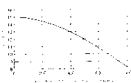
Fig. 5 is the plotted curve of the relation of expression operating load and effective compression ratio;
Fig. 6 is the plotted curve of the opening valve time of expression compression ratio control valve;
Fig. 7 is the coordinate figure of the relation of expression valve-closing time of compression ratio control valve and effective compression ratio;
Fig. 8 is the system diagram that expression relates to the jet accelerating unit of duel fuel engine of the present invention;
Fig. 9 is the sectional arrangement drawing that band sprays the exhaust turbine supercharger of accelerating unit.
Embodiment
Following with reference to the description of drawings embodiments of the present invention.
Fig. 1 and Fig. 3 relate to the side of cylinder head part of duel fuel engine E of the present invention and the sectional arrangement drawing of opposite side, and Fig. 2 is the partial enlarged drawing of Fig. 1.In Fig. 1~Fig. 3, the 1st, the cylinder liner of duel fuel engine E, setting is accompanied by the piston 2 of the rotation reciprocating action of bent axle in cylinder liner 1.The 3rd, have the cylinder head of intakeport 3a and relief opening (not illustrating), the 4th, the main combustion chamber that surrounds by above-mentioned cylinder liner 1, piston 2 and cylinder head 3.The Aspirating valves 5 and the outlet valve (not illustrating) of the interconnecting part that opens and closes intakeport 3a, relief opening and main combustion chamber 4 are set respectively on the intakeport 3a of cylinder head 3 and relief opening (not illustrating).
Intakeport 3a is connected with air suction main 9 on being arranged on cylinder seat 8 by air-breathing menifold 7.Fuel gas supply device 10 is installed on air-breathing menifold 7, and it supplies with combustion gas (gaseous fuel) to main combustion chamber 4.Fuel gas supply device 10 has: be fixed on the air-breathing menifold 7 and bend to L shapedly, point is at the gaspipe 11 of intakeport 3a inner opening; Open and close the solenoid valve 12 of gas supply pipe 11.
Have again, compression ratio control valve 13 is installed, the precombustion chamber unit 15 with electro-magneto fuel injector (liquid fuel injection valve) 14 is installed respectively in both sides at the central part of cylinder head 3.Compression ratio control valve 13 has: cylindric valve body 17, and it is fixed on the inside that mounting or dismounting are mounted freely on the chuck 16 in the cylinder head 3, on the opening portion 17a that is communicated with main combustion chamber 4 valve seat 17b is set; Valve rod 18, its easy on and off inserts in the valve body 17 movably, has the 18a of valve portion that touches with valve seat 17b; Electromagnetic coil 19, it is fixed on the upper end of chuck 16, attracts to be located at the attraction axle 18b action of valve rod 18 upper ends, and valve rod 18 is moved down and open opening portion 17a; Pressure spring 22, it is installed in latch bracket 20 and is fixed between the spring seat 21 that attracts on the axle 18b in the large-diameter portion 17c of valve body 17.Latch bracket 20 is moved downwards by the restriction of the platform portion of the below of large-diameter portion 17c.
On the periphery below the valve body 17, form annular slot 17d.Annular slot 17d is communicated with the inside 17f of valve body 17 by the one or more hole 17e that open in diametric(al) on valve body 17, is communicated with intakeport 3a by the path 3c that opens on cylinder head 3 simultaneously.Also path 3c can be formed the hole of pipe arrangement to replace on cylinder head 3, opening.Have again, valve rod 18 axially is free to slide in valve body 17 on the guiding axial region 18c in chimeric big footpath, ground, connect the above-mentioned valve 18a of portion by path axial region 18d, surface friction drag when sliding for the relative valve body 17 of central part of the guiding axial region 18c that reduces big footpath, its footpath is thin a little, and valve body 17 between form gap 17g.Have again,, be formed for improving the sealing gland groove 17h of the ring-type of sealing at the two end part of guiding axial region 18c.Have again,, also can omit this sealing gland groove 17h as the occasion of present embodiment with electromagnetic coil 19 drivings, yet, replacing electromagnetic coil 19 to make the occasion of valve rod 18 actions, sealing gland groove 17 is set preferably with reactive fluids such as pressurized air.
When such compression ratio control valve 13 is opened above-mentioned opening portion 17a at the 18a of valve portion, will main combustion chamber 4 be communicated with above-mentioned intakeport 3a.
The inside 17f of above-mentioned opening portion 17a, valve body 17, hole 17e, annular slot 17d, path 3c constitute the outdoor vent passage A that is communicated with of main combustion chamber 4 and its, and above-mentioned valve body 17, valve rod 18 etc. constitute the switching mechanism B of the compression ratio control valve 13 that opens and closes above-mentioned vent passage A.
Below, the control gear of duel fuel engine E is described according to Fig. 4.In Fig. 4, the 30th, by the high-pressure service pump of duel fuel engine E crank-driven, it attracts liquid fuel and pressurization in the fuel pot 31, supplies with pressure-accumulating tube 32 by pipe arrangement p1 from solenoid-operated proportional pressure controlled valve 30a.Pressure-accumulating tube 32 is connected on the fuel pot 31 by the pipe arrangement p2 that safety valve 33 has been installed, and can set arbitrarily in the scope of 10~200MPa by the oil pressure of solenoid-operated proportional pressure controlled valve 30a pressurized liquid-fuel oil in pressure-accumulating tube 32.The oilhole 26a that is located at the electro-magneto fuel injector 14 of the precombustion chamber unit 15 on each cylinder of duel fuel engine E is connected on the above-mentioned pressure-accumulating tube 32 via high-voltage tube p3 by joint 26b.
The logical circuit of the running control of the implementation duel fuel engine E that packs in control gear 34 is arranged again.Promptly, when having selected the combustion gas operation mode with the operation mode switch, as representing with a line among Fig. 5, the running of control duel fuel engine E, make effective compression ratio (compression ratio) Pc of main combustion chamber 4 be maintained certain high value from engine start to low-load range L1, change to be changed to low value gradually from above-mentioned high value at the corresponding load of the range L 2 of shoulder load, maintaining above-mentioned low value at high-load range L3 is certain value.Have again, when having selected the Di Saier operation mode, represent as b line among Fig. 5, the running of control duel fuel engine E, when making above-mentioned effective compression ratio Pc and above-mentioned combustion gas operation mode from starting the time low-load range L1 maintain in the same manner on certain high value.
At this, as shown in Figure 6, above-mentioned effective compression ratio Pc is by the switching mechanism B that opens above-mentioned compression ratio control valve 13 in the elapsed time (lower dead centre (BDC)) of the compression stroke of above-mentioned piston 2, gas (is the mixed gas of air and combustion gas when the combustion gas operation mode, at the Di Saier operation mode is air) a part from main combustion chamber 4 is discharged to intakeport 3a via the valve body 17 of compression ratio control valve 13 and the vent passage A the above-mentioned path 3c after, the valve open period T decision of the compression ratio control valve 13 of Te when the valve of the switching mechanism B of compression ratio control valve 13 closes.Have, Px is the pressure of the gas in the main combustion chamber 4 that is made of cylinder liner 1, piston 2, cylinder head 3 etc. among Fig. 6 again.
Promptly, rotation angle with the bent axle of elapsed time (lower dead centre (BCD)) of the compression stroke of piston 2 is 0 °, at this moment, when the switching mechanism B of compression ratio control valve 13 drives valve, as shown in Figure 7 according to the relation of the valve-closing time of the compression ratio control valve 13 of the rotation angle of bent axle and effective compression ratio Pc.
Thereby the valve-closing time of the compression ratio control valve 13 among above-mentioned each load range L1, L2, the L3 is set according to Fig. 5 and relation shown in Figure 7.Like this, the excitation time of the electromagnetic coil 19 of may command compression ratio control valve 13.Particularly, the relation by Fig. 5 for example, form the present load condition decision effective compression ratio (Pc) of control gear 34 from duel fuel engine E, relation by Fig. 7 is from the valve-closing time of effective compression ratio (Pc) the decision compression ratio control valve 13 that determined, according to the excitation time of the electromagnetic coil 19 of this valve-closing time that is determined control compression ratio control valve 13.
Have again, set the electro-magneto fuel injector 14 of precombustion chamber unit 15, make it can spray liquid fuel as the necessary certain pilot quantity of the incendiary source of the combustion gas (gaseous fuel) of main combustion chamber 4 and Air mixing gas (account for full heat ratio about 1%) at the combustion gas operation mode; Make it can spray the liquid fuel of the operating load amount of corresponding motor by speed regulating control at the Di Saier operation mode.
Below, the effect of the duel fuel engine E of above-mentioned formation is described.
Select the Di Saier operation mode with the operation mode switch, when in this switching signal i3 input control device 34, the electromagnetic coil 19 of gas shutoff valve 36, electromagnetic valve driver 37, compression ratio control valve 13 just sent into command signal f1, f2, f3 respectively by control gear 34, the solenoid valve 12 of gas shutoff valve 36 and fuel gas supply device 10 cuts out, stop to supply with combustion gas to intakeport 3a, the 18a of valve portion of compression ratio control valve 13 closes opening portion 17a simultaneously, and the connection of main combustion chamber 4 and vent passage A is compressed than control valve 13 and cuts off.
Have again, command signal f5 is sent to the solenoid-operated proportional control valve 30a of high-pressure service pump 30 by control gear 34, according to checkout value from pressure transducer 38, liquid fuel in the control pressure-accumulating tube 32 is with the pressure pressure accumulation of regulation, simultaneously, command signal f4 is sent to the electro-magneto fuel injector 14 of each precombustion chamber unit 15, and setting electro-magneto fuel injector 14 is the speed regulating control state.Promptly, by signal i2 according to the sensor value of the revolution of detection of engine, power, control gear 34 is in order to keep the revolution of regulation, send the ETAD expected time of arrival and departure that command signal f4 controls nozzle by electromagnetic coil 14a, make the liquid fuel that sprays corresponding operating load amount from electro-magneto fuel injector 14 to precombustion chamber 24a to electro-magneto fuel injector 14.From the liquid fuel that electro-magneto fuel injector 14 sprays, after the air igniting that in precombustion chamber 24a, is imported, spray in main combustion chamber 4 from jetburner 25a from main combustion chamber, in air, burn by the high compression ratio compression that is suitable for the Di Saier running.
At this Di Saier operation mode, because motor turns round in the liquid fuel precombustion mode of ignition in precombustion chamber 24a as main fuel, so NO
XDischarge concentration be suppressed.
Select the combustion gas operation mode with the operation mode switch, when from Di Saier running during to the switching signal i3 input control device 34 of combustion gas running, the electro-magneto fuel injector 14 of gas shutoff valve 36, electromagnetic valve driver 37, each precombustion chamber unit 15 just sent into command signal f1, f2, f4 respectively by control gear 34, gas shutoff valve 36 is opened, and reduces and be fixed on the setting value of above-mentioned pilot quantity (account for full heat ratio 1%) gradually from the emitted dose of the liquid fuel of electromagnetic type combustion injection valve 14.Simultaneously, electromagnetic valve driver 37 opens the solenoid valve 12 of fuel gas supplier 10 by speed regulating control, and main fuel is switched into combustion gas.This switches in arbitrarily, and load can carry out.
When switching this operation, send the command signal f3 of control excitation times from the electromagnetic coil 19 of 34 pairs of compression ratio control valves 13 of control gear, make the valve-closing time Te of switching mechanism B of range L 1, the compression ratio control valve 13 among L2, the L3 of above-mentioned each load become set condition according to the relation shown in Fig. 5 and Fig. 7.
The combustion gas running after the Di Saier running is switched, make electromagnetic valve driver 37 actions carry out speed regulating control by command signal f2 with control gear 34, promptly, the control gas quantity makes the revolution of motor certain, because adjust the ETAD expected time of arrival and departure of solenoid valve 12, so can supply with the fuel gas of the amount of corresponding operating load in the intakeport 3a via the gas supply pipe 11 of fuel gas supply device 10 from fuel tube 35.This combustion gas with send into the air mixing of intakeport 3a from air suction main 9 via air-breathing menifold 7 and be imported in the main combustion chamber 4 after compression stroke is compressed, a part is lighted a fire by the liquid fuel of the above-mentioned pilot quantity of spraying from electro-magneto fuel injector 14 in the precombustion chamber 24a of precombustion chamber unit 15, and jets out flames from jetburner 25a.Then, be incendiary source with this flame, the mixed gas in the burning main combustion chamber 4.
At this moment, when the starting of combustion gas running or during low-load, it is short from the time (valve open period T) of reaching the pass when the beginning of compression stroke to set compression ratio control valve 13, the vent passage A that forms via opening portion 17a, the hole 17e of compression ratio control valve 13, annular slot 17d, path 3c from main combustion chamber 4, the mixed gas that flows out to intakeport 3a is few, sets the compression ratio height of mixed gas.As a result, even the ignition by compression of the liquid fuel of pilot quantity does not use ignition combustion modes such as igniter plug or glowing plug to carry out well yet, can pilot engine.
Thereby, can not carry out starting fast reliably even do not carry out warm-operation by the motor of combustion gas running yet, can successfully carry out low load operation at the state that improves the thermal efficiency and combustion stability simultaneously.Have again,, can make the simple in structure of motor like this, reduce number of spare parts, increase reliability, have the low advantage of manufacturing expenses simultaneously because do not need ignition mechanism.
Have, when high load, the opening valve time T that sets above-mentioned compression ratio control valve 13 is long again, and the mixed gas that flows out to intakeport 3a from main combustion chamber 4 increases, and the compression ratio of setting mixed gas is low.Have again, during shoulder load between low-load and high load, along with the increase of load, the compression ratio the when compression ratio of control compression ratio during from low-load slowly is reduced to high load.
Therefore, when respectively loading, motor can not cause pinking above-mentioned, and the burning of the combustion gas in the main combustion chamber 4 can be carried out well, can successfully carry out the combustion gas running when obtaining the high thermal efficiency.
Have, when combustion gas was turned round, by being burnt by the ignition by compression of the liquid fuel of pilot quantity, emitted dose can be few (account for full heat ratio about 1%) again.The NO that fluid combustion when as a result, the control of energy utmost point lowland is by igniting produces
XWith the discharge concentration of dust, can fully satisfy exhaust limits value to the combustion gas running.
Have again, by the switching of combustion gas running to the operation mode of Di Saier running, remove from the pilot quantity that is fixed on certain value by the emitted dose of when the command signal f1 by control gear 34 closes burnt gas switch valve 36, the liquid fuel of electro-magneto fuel injector 14 being set, simultaneously to electromagnetic coil 19 demagnetizations of compression ratio control valve 13 and closes compression is easily carried out than control valve 13 by command signal f4.That is, when electromagnetic coil 19 demagnetizations, valve rod 18 is compressed spring 22 and upsprings upwards, and the opening portion 17a of valve core 18a valve body 17 cuts off the connection of main combustion chamber 4 and vent passage A by the switching mechanism B of compression ratio control valve 13.As a result, the air in the main combustion chamber 4 can not flow to intakeport 3a, and the compression ratio of air is set in the high value that is suitable for the Di Saier running.Thereby the injection of the liquid fuel that is undertaken by electro-magneto fuel injector 14 can directly be implemented by the speed regulating control of correspondence load.
Have again, in the duel fuel engine E of the foregoing description, because as set the switching time of compression ratio control valve 13 followingly, promptly, when the elapsed time of carrying out the compression stroke of gas by piston 2 is opened valve, the rotation angle of the engine crankshaft during with the beginning of this compression stroke is crank angle that benchmark reaches a regulation cut-off valve when spending, for example, rotation angle with the engine crankshaft in beginning period of the compression stroke of piston 2 is 0 °, the angle cut-off valve that rotates according to this bent axle is so the setting of the effective compression ratio in the main combustion chamber 4 can correctly be carried out and extremely desirable.Yet, also being not limited to this, the switching time of compression ratio control valve 13 also can be set in other the moment in the time of both can having begun in the compression stroke of piston 2.
Have again, in the duel fuel engine E of the foregoing description, in order to regulate the combustion gas in the main combustion chamber 4 and the compression ratio of Air mixing gas, will flow into intakeport 3a by the vent passage 3c that compression ratio control valve 13 makes main combustion chamber 4 interior mixed gass pass through cylinder head 3, yet, also can be alternatively, as Fig. 8 and shown in Figure 9, also can be on the impeller 40a of the gas compressor 40 that is being attached to the exhaust turbine supercharger Tc on the duel fuel engine E from main combustion chamber 4 to its outside mixing air-blowing of flowing out.
At this moment, on the compression ratio control valve 13 that is installed in by chuck 16 grades on the cylinder head 3, be arranged on the vent 41 of the upper opening of cylinder 3 along its axle direction.The lower end of vent 41 and above-mentioned hole 17e are communicated with, and the air-breathing menifold 44 of insertion of formation is connected around the impeller 40a of upper end by pipe arrangement 43 and gas compressor 40 on exhaust turbine supercharger Tc.Opened a plurality of injections towards the peripheral part of the impeller 40a of gas compressor 40 along circumferencial direction and quickened endoporus 45 inserting on the air-breathing menifold 44, made from the compressed mixed gas of main combustion chamber 4 and quicken endoporus 45 and blow on compressor turbine 40 from spraying.
Have again, in Fig. 8, the 42nd, by the exhaust driven gas turbine from the exhaust gas drive of the exhaust port (not shown) of duel fuel engine E, G is the output loading devices such as generator that driven by motor E.
Like this, when mixing on the impeller 40a of air-blowing at the gas compressor on the exhaust turbine supercharger Tc 40, just can improve the transient response of exhaust turbine supercharger Tc, increase the air quantity of sending into main combustion chamber 4, the effect of delivery temperature in the time of like this, obtaining to reduce low-load and minimizing black smoke discharge capacity.
Claims (10)
1. duel fuel engine, its main combustion chamber by cylinder and in this cylinder pistons reciprocating and cylinder head form, described cylinder head has the intakeport of loading onto Aspirating valves and the relief opening of loading onto outlet valve; In main combustion chamber,,, in gaseous fuel and the liquid fuel any obtain output drive strength in by the gas of above-mentioned Piston Compression by being burnt according to operation mode; It is characterized in that,
Be provided with: the precombustion chamber unit, it is in above-mentioned cylinder head, liquid fuel with the certain pilot quantity of when combustion gas operation mode ejection, ejection is corresponding to the liquid fuel injection valve of the liquid fuel of operating load during the liquid fuel within operation mode, and have the above-mentioned pressurized gas of introducing, make from the precombustion chamber of the liquid fuel combustion of aforesaid liquid fuel injection valves inject; Compression ratio control valve, it is arranged on and is communicated with on above-mentioned main combustion chamber and its outdoor vent passage, opens and closes above-mentioned vent passage at the initial stage by above-mentioned Piston Compression gas and makes a part of pressurized gas enter described vent passage and the compression ratio that changes above-mentioned gas; The fuel gas supply device, it is supply gas fuel in above-mentioned main combustion chamber.
2. duel fuel engine as claimed in claim 1, it is characterized in that, above-mentioned compression ratio control valve is when the combustion gas operation mode, starting, low-load, the high loaded process state of corresponding motor, adjust the switching time of above-mentioned vent passage, adjust compression ratio in starting, during low-load and increase, adjust compression ratio during at high load and reduce.
3. duel fuel engine as claimed in claim 2, it is characterized in that, as the switching time of the above-mentioned compression ratio control valve of following setting, that is: the corner that begins the engine crankshaft in period with this compression stroke when the elapsed time of being carried out the compression stroke of gas by described piston is opened valve is a benchmark, cut-off valve when reaching the crank angle of regulation.
4. as any described duel fuel engine in the claim 1~3, it is characterized in that above-mentioned fuel gas supply device has: connect the gas supply pipe of above-mentioned intakeport, adjusting drives this solenoid valve switching to the solenoid valve of the delivery volume of the gaseous fuel of gas supply pipe, by speed regulating control from gas fuel source electromagnetic valve driver; Can by the aforesaid liquid Fuelinjection nozzle carry out pilot quantity liquid fuel injection and carry out the injection of liquid fuel by speed regulating control; Have again, drive above-mentioned compression ratio control valve by electromagnetic coil, thus can be according to the operating condition of motor, adjust from valve and open and be communicated with above-mentioned main combustion chamber and above-mentioned vent passage and close and cut off the opening valve time of this access to valve; Have again, on above-mentioned electromagnetic valve driver, aforesaid liquid Fuelinjection nozzle and above-mentioned electromagnetic coil, connect the control gear that makes their actions, this control gear is according to the operation mode action of selecting, when combustion gas is turned round, for being opened and closed, above-mentioned solenoid valve makes above-mentioned electromagnetic valve driver action, the liquid fuel of jet-ignition amount makes the action of aforesaid liquid Fuelinjection nozzle, simultaneously, the opening valve time of regulating above-mentioned compression ratio control valve according to the operating condition of motor makes above-mentioned electromagnetic coil action; When Di Saier turns round, close above-mentioned solenoid valve and make above-mentioned electromagnetic valve driver action, make the action of aforesaid liquid Fuelinjection nozzle by the speed regulating control injecting LPG in liquefied condition, simultaneously, close above-mentioned compression ratio control valve and make above-mentioned electromagnetic coil action.
5. as any described duel fuel engine in the claim 1~3, it is characterized in that above-mentioned vent passage and above-mentioned intakeport are communicated with.
6. duel fuel engine as claimed in claim 4 is characterized in that, above-mentioned vent passage and above-mentioned intakeport are communicated with.
7. as any described duel fuel engine in the claim 1~3, it is characterized in that above-mentioned vent passage is connected by the exhaust gas drive of above-mentioned relief opening and supplies with to above-mentioned intakeport on the air-breathing menifold of insertion of exhaust turbine supercharger of forced air.
8. duel fuel engine as claimed in claim 4 is characterized in that, above-mentioned vent passage is connected by the exhaust gas drive of above-mentioned relief opening and supplies with to above-mentioned intakeport on the air-breathing menifold of insertion of exhaust turbine supercharger of forced air.
9. duel fuel engine as claimed in claim 5 is characterized in that, above-mentioned vent passage is connected by the exhaust gas drive of above-mentioned relief opening and supplies with to above-mentioned intakeport on the air-breathing menifold of insertion of exhaust turbine supercharger of forced air.
10. duel fuel engine as claimed in claim 6 is characterized in that, above-mentioned vent passage is connected by the exhaust gas drive of above-mentioned relief opening and supplies with to above-mentioned intakeport on the air-breathing menifold of insertion of exhaust turbine supercharger of forced air.
Applications Claiming Priority (1)
| Application Number | Priority Date | Filing Date | Title |
|---|---|---|---|
| PCT/JP2001/011364 WO2003056159A1 (en) | 2001-12-25 | 2001-12-25 | Dual fuel engine |
Publications (2)
| Publication Number | Publication Date |
|---|---|
| CN1500179A CN1500179A (en) | 2004-05-26 |
| CN1288335C true CN1288335C (en) | 2006-12-06 |
Family
ID=11738067
Family Applications (1)
| Application Number | Title | Priority Date | Filing Date |
|---|---|---|---|
| CNB018230156A Expired - Lifetime CN1288335C (en) | 2001-12-25 | 2001-12-25 | Dual fuel engine |
Country Status (10)
| Country | Link |
|---|---|
| US (1) | US6814032B2 (en) |
| EP (1) | EP1460250B1 (en) |
| KR (1) | KR100756281B1 (en) |
| CN (1) | CN1288335C (en) |
| AT (1) | ATE440210T1 (en) |
| DE (1) | DE60139645D1 (en) |
| DK (1) | DK1460250T3 (en) |
| ES (1) | ES2331945T3 (en) |
| NO (1) | NO337532B1 (en) |
| WO (1) | WO2003056159A1 (en) |
Families Citing this family (55)
| Publication number | Priority date | Publication date | Assignee | Title |
|---|---|---|---|---|
| CA2406137C (en) * | 2002-10-02 | 2004-12-28 | Westport Research Inc. | Control method and apparatus for gaseous fuelled internal combustion engine |
| US7007661B2 (en) * | 2004-01-27 | 2006-03-07 | Woodward Governor Company | Method and apparatus for controlling micro pilot fuel injection to minimize NOx and UHC emissions |
| DE102005028553A1 (en) * | 2005-06-21 | 2007-01-04 | Daimlerchrysler Ag | Hybrid-fuel-internal combustion engine e.g. diesel-internal combustion engine, has control device regulating injectors based on engine operating point and composition of combustion gases that is detected by exhaust gas sensor |
| US7270092B2 (en) * | 2005-08-12 | 2007-09-18 | Hefley Carl D | Variable displacement/compression engine |
| JP2007085280A (en) * | 2005-09-26 | 2007-04-05 | Honda Motor Co Ltd | Internal combustion engine |
| JP5114046B2 (en) * | 2006-03-13 | 2013-01-09 | 日産自動車株式会社 | Variable expansion ratio engine |
| US20070266990A1 (en) * | 2006-05-16 | 2007-11-22 | Sims John T | Variable compression engine |
| EP1950409B1 (en) | 2007-01-29 | 2015-12-02 | Robert Bosch Gmbh | Method and device for operating a gas injection system of a gas fuel and a liquid fuel operated internal combustion engine |
| US20090076705A1 (en) * | 2007-09-13 | 2009-03-19 | Colesworthy Robert L | Power modulated, dual fuel, small displacement engine control system |
| US7617684B2 (en) * | 2007-11-13 | 2009-11-17 | Opra Technologies B.V. | Impingement cooled can combustor |
| US20090165435A1 (en) * | 2008-01-02 | 2009-07-02 | Michal Koranek | Dual fuel can combustor with automatic liquid fuel purge |
| DE102008007325A1 (en) * | 2008-02-02 | 2009-08-13 | Man Diesel Se | Test method for ignition fluid injectors |
| US7890241B2 (en) | 2008-05-21 | 2011-02-15 | Ford Global Technologies, Llc | Boosted engine control responsive to driver selected performance |
| US8631574B2 (en) * | 2009-06-10 | 2014-01-21 | Ford Global Technologies, Llc | Method for molding products adapted for use in different applications |
| DE102009051137A1 (en) * | 2009-06-26 | 2011-01-05 | Mtu Friedrichshafen Gmbh | Method for operating an internal combustion engine |
| US7913673B2 (en) * | 2009-06-30 | 2011-03-29 | Clean Air Power, Inc. | Method and apparatus for controlling liquid fuel delivery during transition between modes in a multimode engine |
| DE102009033861A1 (en) * | 2009-07-16 | 2010-02-04 | Daimler Ag | Internal-combustion engine operating method for vehicle, involves injecting liquid fuel into combustion chamber directly, during start-stop operation, and operating internal-combustion engine in start-stop operation |
| US8613187B2 (en) * | 2009-10-23 | 2013-12-24 | General Electric Company | Fuel flexible combustor systems and methods |
| WO2011109514A1 (en) | 2010-03-02 | 2011-09-09 | Icr Turbine Engine Corporatin | Dispatchable power from a renewable energy facility |
| CN101834105B (en) * | 2010-03-30 | 2011-10-05 | 洛阳高拓机械设备有限公司 | Fuel gas mixing bag for producting energy saving lamp |
| US8984895B2 (en) | 2010-07-09 | 2015-03-24 | Icr Turbine Engine Corporation | Metallic ceramic spool for a gas turbine engine |
| US20120085326A1 (en) * | 2010-10-10 | 2012-04-12 | Feng Mo | Method and apparatus for converting diesel engines to blended gaseous and diesel fuel engines |
| JP5338997B2 (en) * | 2011-02-16 | 2013-11-13 | トヨタ自動車株式会社 | Multi-fuel internal combustion engine and control method thereof |
| JP5675466B2 (en) * | 2011-03-31 | 2015-02-25 | 三菱重工業株式会社 | Pilot injection timing control method and apparatus when engine combustion diagnosis signal is abnormal |
| US9051873B2 (en) | 2011-05-20 | 2015-06-09 | Icr Turbine Engine Corporation | Ceramic-to-metal turbine shaft attachment |
| US9279370B2 (en) | 2011-10-28 | 2016-03-08 | General Electric Company | Turbomachine and method of operating a turbomachine to perform a fuel change over at a high load |
| KR101734583B1 (en) * | 2011-12-13 | 2017-05-12 | 현대자동차주식회사 | Combustion generating device for internal combustion engine |
| JP2013234652A (en) * | 2012-04-13 | 2013-11-21 | Denso Corp | Engine control device |
| ITBO20120303A1 (en) * | 2012-06-04 | 2013-12-05 | Brum S R L | SYSTEM FOR THE SUPPLY OF AN INTERNAL COMBUSTION ENGINE |
| WO2014004984A1 (en) * | 2012-06-29 | 2014-01-03 | Icr Turbine Engine Corporation | Lng fuel handling for a gas turbine engine |
| US10094288B2 (en) | 2012-07-24 | 2018-10-09 | Icr Turbine Engine Corporation | Ceramic-to-metal turbine volute attachment for a gas turbine engine |
| DE102013004875A1 (en) * | 2013-03-15 | 2014-09-18 | Andreas Stihl Ag & Co. Kg | "Internal combustion engine with a suction device" |
| JP6069062B2 (en) * | 2013-03-22 | 2017-01-25 | 川崎重工業株式会社 | Fuel supply control device for sub-chamber gas engine |
| DE102013213349B4 (en) * | 2013-03-28 | 2017-10-05 | Mtu Friedrichshafen Gmbh | Method for operating a dual-fuel internal combustion engine, control for a dual-fuel internal combustion engine and dual-fuel internal combustion engine |
| CA2819721C (en) * | 2013-06-27 | 2014-07-08 | Westport Power Inc. | Engine control apparatus |
| JP6297363B2 (en) * | 2014-02-28 | 2018-03-20 | 三菱重工業株式会社 | Dual fuel engine, ship equipped with the same, and control method of dual fuel engine |
| KR101912513B1 (en) | 2014-06-06 | 2018-10-26 | 얀마 가부시키가이샤 | Engine device |
| EP3153684B1 (en) | 2014-06-06 | 2020-03-04 | Yanmar Co., Ltd. | Engine device |
| US9689333B2 (en) * | 2014-07-28 | 2017-06-27 | Cummins Inc. | Dual-fuel engine with enhanced cold start capability |
| US10584639B2 (en) | 2014-08-18 | 2020-03-10 | Woodward, Inc. | Torch igniter |
| JP6594714B2 (en) * | 2015-09-16 | 2019-10-23 | ヤンマー株式会社 | Engine equipment |
| JP6517117B2 (en) * | 2015-09-16 | 2019-05-22 | ヤンマー株式会社 | Engine equipment |
| EP3431740A4 (en) * | 2016-03-14 | 2019-10-09 | Niigata Power Systems Co., Ltd. | Engine system and control method therefor |
| US9903284B1 (en) | 2016-10-31 | 2018-02-27 | General Electric Company | Dual-fuel engine system and method having the same |
| JP6606523B2 (en) * | 2017-03-29 | 2019-11-13 | ヤンマー株式会社 | Engine equipment |
| US9752515B1 (en) | 2017-04-03 | 2017-09-05 | James A. Stroup | System, method, and apparatus for injecting a gas in a diesel engine |
| CN112020601B (en) | 2018-04-25 | 2023-03-21 | 沃尔沃卡车集团 | Internal combustion engine arrangement and method of controlling operation thereof |
| KR101976713B1 (en) * | 2018-11-07 | 2019-05-10 | 현대중공업 주식회사 | Otto cycle type Engine and Ship having the same and Driving Method of Propulsion Apparatus for Ship |
| CN109723547B (en) * | 2019-01-30 | 2023-08-15 | 一汽解放汽车有限公司 | Flexible fuel engine and control method |
| US10982601B2 (en) * | 2019-03-15 | 2021-04-20 | Caterpillar Inc. | Combustion control system and method for switching between spark and pilot-ignited operating modes in dual fuel engine |
| US11421601B2 (en) | 2019-03-28 | 2022-08-23 | Woodward, Inc. | Second stage combustion for igniter |
| KR102442213B1 (en) * | 2019-04-03 | 2022-09-13 | 현대중공업 주식회사 | dual-fuel engine |
| CN110671190A (en) * | 2019-10-10 | 2020-01-10 | 天津大学 | Jet flow disturbance enhanced combustion system of pre-combustion chamber |
| JP2020008025A (en) * | 2019-10-18 | 2020-01-16 | ヤンマー株式会社 | Engine device |
| CN114198214A (en) * | 2021-12-15 | 2022-03-18 | 北油电控燃油喷射系统(天津)有限公司 | Control method of interactive combustion-supporting dual-fuel internal combustion engine injection system |
Family Cites Families (11)
| Publication number | Priority date | Publication date | Assignee | Title |
|---|---|---|---|---|
| US5050550A (en) * | 1990-07-11 | 1991-09-24 | Litang Gao | Hybrid step combustion system |
| US5201907A (en) * | 1991-06-28 | 1993-04-13 | Mazda Motor Corporation | Internal combustion engine |
| JPH084562A (en) * | 1994-06-17 | 1996-01-09 | Isuzu Ceramics Kenkyusho:Kk | Multi-fuel engine |
| DE19621297C1 (en) * | 1996-05-28 | 1997-12-04 | Man B & W Diesel Ag | Device for control and regulation of ignition oil injection in gas engine |
| JPH10238374A (en) | 1997-02-21 | 1998-09-08 | Daihatsu Motor Co Ltd | Premixture ignition internal combustion engine and ignition timing control method |
| BR9904839A (en) * | 1998-02-23 | 2000-07-18 | Cummins Engine Co Inc | Compression blast engine with pre-mixed load with optimum combustion control |
| JPH11324750A (en) | 1998-05-13 | 1999-11-26 | Niigata Eng Co Ltd | Combined engine and its operating method |
| JP2000110595A (en) | 1998-10-09 | 2000-04-18 | Tokyo Gas Co Ltd | Dual fuel engine and its control method |
| JP2001193512A (en) | 2000-01-11 | 2001-07-17 | Hiromasa Kitaguchi | Engine having functions of gasoline and diesel |
| JP3647355B2 (en) | 2000-04-25 | 2005-05-11 | 大阪瓦斯株式会社 | Operation method of sub-chamber combustion engine |
| JP3676964B2 (en) * | 2000-06-27 | 2005-07-27 | 新潟原動機株式会社 | Dual fuel engine |
-
2001
- 2001-12-25 AT AT01275100T patent/ATE440210T1/en active
- 2001-12-25 KR KR1020037011460A patent/KR100756281B1/en active IP Right Grant
- 2001-12-25 CN CNB018230156A patent/CN1288335C/en not_active Expired - Lifetime
- 2001-12-25 US US10/469,212 patent/US6814032B2/en not_active Expired - Lifetime
- 2001-12-25 WO PCT/JP2001/011364 patent/WO2003056159A1/en active Application Filing
- 2001-12-25 ES ES01275100T patent/ES2331945T3/en not_active Expired - Lifetime
- 2001-12-25 DE DE60139645T patent/DE60139645D1/en not_active Expired - Lifetime
- 2001-12-25 EP EP01275100A patent/EP1460250B1/en not_active Expired - Lifetime
- 2001-12-25 DK DK01275100T patent/DK1460250T3/en active
-
2003
- 2003-08-22 NO NO20033734A patent/NO337532B1/en not_active IP Right Cessation
Also Published As
| Publication number | Publication date |
|---|---|
| DK1460250T3 (en) | 2009-12-21 |
| EP1460250A1 (en) | 2004-09-22 |
| NO20033734D0 (en) | 2003-08-22 |
| EP1460250B1 (en) | 2009-08-19 |
| NO337532B1 (en) | 2016-05-02 |
| EP1460250A4 (en) | 2008-03-05 |
| ES2331945T3 (en) | 2010-01-21 |
| WO2003056159A1 (en) | 2003-07-10 |
| NO20033734L (en) | 2003-09-24 |
| KR20040063080A (en) | 2004-07-12 |
| ATE440210T1 (en) | 2009-09-15 |
| EP1460250A8 (en) | 2005-01-19 |
| DE60139645D1 (en) | 2009-10-01 |
| US6814032B2 (en) | 2004-11-09 |
| KR100756281B1 (en) | 2007-09-06 |
| US20040065293A1 (en) | 2004-04-08 |
| CN1500179A (en) | 2004-05-26 |
Similar Documents
| Publication | Publication Date | Title |
|---|---|---|
| CN1288335C (en) | Dual fuel engine | |
| CN101427019B (en) | Low emission high performance engines, multiple cylinder engines and operating methods | |
| CN1052294C (en) | Two-cycle utility internal combustion engine | |
| CN100362223C (en) | Combustion control device for an engine | |
| US4955326A (en) | Low emission dual fuel engine and method of operating same | |
| CN103925119B (en) | Gas common rail fuel system and the high compression engine using the system | |
| KR101931840B1 (en) | A two-stroke internal combustion engine, method operating a two-stroke internal combustion engine and method of converting a two-stroke engine | |
| US6427660B1 (en) | Dual fuel compression ignition engine | |
| CN1723343B (en) | Control method and apparatus for gaseous fuelled internal combustion engine | |
| CN1309946C (en) | IC engine and its controller | |
| CN1425107A (en) | Gaseous and liquid fuel injector with two-way hydraulic fluid control valve | |
| CN1072308C (en) | Method and device for jetting gas fuel at high speed into internal combustion engine | |
| CN102312739A (en) | Vehicle-mounted DENG and controlling method thereof with turbosupercharger | |
| US7261097B2 (en) | EGR system for spark-ignited gasoline engine | |
| CN102374058A (en) | Method and device for controlling diesel engine with forced induction system | |
| CN103052789B (en) | Explosive motor, combustion charge form system and method | |
| JP2002004899A (en) | Dual fuel engine | |
| CN102400817A (en) | Method for operating an internal combustion engine having spark ignition unit | |
| CN1435562A (en) | Water jet device of engine | |
| US20090183491A1 (en) | Internal continuous combustion engine system | |
| CN1502008A (en) | Starting apparatus for igniting ignition gas engine | |
| EP1373694B1 (en) | Method of controlling the injection of fluid into an internal combustion engine | |
| KR20220100042A (en) | Method and gas fuel injection unit for operating an internal combustion engine | |
| CN114109637B (en) | Combustion control method and device of diesel engine and diesel engine | |
| CN101346536B (en) | Internal combustion engine |
Legal Events
| Date | Code | Title | Description |
|---|---|---|---|
| C06 | Publication | ||
| PB01 | Publication | ||
| C10 | Entry into substantive examination | ||
| SE01 | Entry into force of request for substantive examination | ||
| C14 | Grant of patent or utility model | ||
| GR01 | Patent grant | ||
| CX01 | Expiry of patent term | ||
| CX01 | Expiry of patent term |
Granted publication date: 20061206 |