CN1230120C - MRI-guided therapeutic unit and method - Google Patents

MRI-guided therapeutic unit and method Download PDF

Info

Publication number
CN1230120C
CN1230120C CNB988053594A CN98805359A CN1230120C CN 1230120 C CN1230120 C CN 1230120C CN B988053594 A CNB988053594 A CN B988053594A CN 98805359 A CN98805359 A CN 98805359A CN 1230120 C CN1230120 C CN 1230120C
Authority
CN
China
Prior art keywords
magnetic resonance
equipment
energy
therapist
field magnet
Prior art date
Legal status (The legal status is an assumption and is not a legal conclusion. Google has not performed a legal analysis and makes no representation as to the accuracy of the status listed.)
Expired - Lifetime
Application number
CNB988053594A
Other languages
Chinese (zh)
Other versions
CN1257414A (en
Inventor
戴维·E·阿克
马克·瓦格肖
Current Assignee (The listed assignees may be inaccurate. Google has not performed a legal analysis and makes no representation or warranty as to the accuracy of the list.)
Koninklijke Philips NV
Original Assignee
Transurgical Inc
Priority date (The priority date is an assumption and is not a legal conclusion. Google has not performed a legal analysis and makes no representation as to the accuracy of the date listed.)
Filing date
Publication date
Application filed by Transurgical Inc filed Critical Transurgical Inc
Publication of CN1257414A publication Critical patent/CN1257414A/en
Application granted granted Critical
Publication of CN1230120C publication Critical patent/CN1230120C/en
Anticipated expiration legal-status Critical
Expired - Lifetime legal-status Critical Current

Links

Images

Classifications

    • AHUMAN NECESSITIES
    • A61MEDICAL OR VETERINARY SCIENCE; HYGIENE
    • A61NELECTROTHERAPY; MAGNETOTHERAPY; RADIATION THERAPY; ULTRASOUND THERAPY
    • A61N7/00Ultrasound therapy
    • A61N7/02Localised ultrasound hyperthermia
    • AHUMAN NECESSITIES
    • A61MEDICAL OR VETERINARY SCIENCE; HYGIENE
    • A61BDIAGNOSIS; SURGERY; IDENTIFICATION
    • A61B34/00Computer-aided surgery; Manipulators or robots specially adapted for use in surgery
    • A61B34/70Manipulators specially adapted for use in surgery
    • A61B34/76Manipulators having means for providing feel, e.g. force or tactile feedback
    • AHUMAN NECESSITIES
    • A61MEDICAL OR VETERINARY SCIENCE; HYGIENE
    • A61BDIAGNOSIS; SURGERY; IDENTIFICATION
    • A61B5/00Measuring for diagnostic purposes; Identification of persons
    • A61B5/05Detecting, measuring or recording for diagnosis by means of electric currents or magnetic fields; Measuring using microwaves or radio waves 
    • A61B5/055Detecting, measuring or recording for diagnosis by means of electric currents or magnetic fields; Measuring using microwaves or radio waves  involving electronic [EMR] or nuclear [NMR] magnetic resonance, e.g. magnetic resonance imaging
    • AHUMAN NECESSITIES
    • A61MEDICAL OR VETERINARY SCIENCE; HYGIENE
    • A61BDIAGNOSIS; SURGERY; IDENTIFICATION
    • A61B17/00Surgical instruments, devices or methods, e.g. tourniquets
    • A61B17/22Implements for squeezing-off ulcers or the like on the inside of inner organs of the body; Implements for scraping-out cavities of body organs, e.g. bones; Calculus removers; Calculus smashing apparatus; Apparatus for removing obstructions in blood vessels, not otherwise provided for
    • A61B2017/22082Implements for squeezing-off ulcers or the like on the inside of inner organs of the body; Implements for scraping-out cavities of body organs, e.g. bones; Calculus removers; Calculus smashing apparatus; Apparatus for removing obstructions in blood vessels, not otherwise provided for after introduction of a substance
    • A61B2017/22087Implements for squeezing-off ulcers or the like on the inside of inner organs of the body; Implements for scraping-out cavities of body organs, e.g. bones; Calculus removers; Calculus smashing apparatus; Apparatus for removing obstructions in blood vessels, not otherwise provided for after introduction of a substance photodynamic
    • AHUMAN NECESSITIES
    • A61MEDICAL OR VETERINARY SCIENCE; HYGIENE
    • A61BDIAGNOSIS; SURGERY; IDENTIFICATION
    • A61B34/00Computer-aided surgery; Manipulators or robots specially adapted for use in surgery
    • A61B34/70Manipulators specially adapted for use in surgery
    • A61B34/74Manipulators with manual electric input means
    • A61B2034/742Joysticks
    • AHUMAN NECESSITIES
    • A61MEDICAL OR VETERINARY SCIENCE; HYGIENE
    • A61BDIAGNOSIS; SURGERY; IDENTIFICATION
    • A61B90/00Instruments, implements or accessories specially adapted for surgery or diagnosis and not covered by any of the groups A61B1/00 - A61B50/00, e.g. for luxation treatment or for protecting wound edges
    • A61B90/04Protection of tissue around surgical sites against effects of non-mechanical surgery, e.g. laser surgery
    • A61B2090/0472Protection of tissue around surgical sites against effects of non-mechanical surgery, e.g. laser surgery against ultrasound energy
    • AHUMAN NECESSITIES
    • A61MEDICAL OR VETERINARY SCIENCE; HYGIENE
    • A61BDIAGNOSIS; SURGERY; IDENTIFICATION
    • A61B90/00Instruments, implements or accessories specially adapted for surgery or diagnosis and not covered by any of the groups A61B1/00 - A61B50/00, e.g. for luxation treatment or for protecting wound edges
    • A61B90/36Image-producing devices or illumination devices not otherwise provided for
    • A61B90/37Surgical systems with images on a monitor during operation
    • A61B2090/374NMR or MRI
    • AHUMAN NECESSITIES
    • A61MEDICAL OR VETERINARY SCIENCE; HYGIENE
    • A61BDIAGNOSIS; SURGERY; IDENTIFICATION
    • A61B90/00Instruments, implements or accessories specially adapted for surgery or diagnosis and not covered by any of the groups A61B1/00 - A61B50/00, e.g. for luxation treatment or for protecting wound edges
    • A61B90/10Instruments, implements or accessories specially adapted for surgery or diagnosis and not covered by any of the groups A61B1/00 - A61B50/00, e.g. for luxation treatment or for protecting wound edges for stereotaxic surgery, e.g. frame-based stereotaxis
    • AHUMAN NECESSITIES
    • A61MEDICAL OR VETERINARY SCIENCE; HYGIENE
    • A61FFILTERS IMPLANTABLE INTO BLOOD VESSELS; PROSTHESES; DEVICES PROVIDING PATENCY TO, OR PREVENTING COLLAPSING OF, TUBULAR STRUCTURES OF THE BODY, e.g. STENTS; ORTHOPAEDIC, NURSING OR CONTRACEPTIVE DEVICES; FOMENTATION; TREATMENT OR PROTECTION OF EYES OR EARS; BANDAGES, DRESSINGS OR ABSORBENT PADS; FIRST-AID KITS
    • A61F7/00Heating or cooling appliances for medical or therapeutic treatment of the human body
    • AHUMAN NECESSITIES
    • A61MEDICAL OR VETERINARY SCIENCE; HYGIENE
    • A61NELECTROTHERAPY; MAGNETOTHERAPY; RADIATION THERAPY; ULTRASOUND THERAPY
    • A61N7/00Ultrasound therapy
    • A61N2007/0056Beam shaping elements
    • A61N2007/0065Concave transducers
    • AHUMAN NECESSITIES
    • A61MEDICAL OR VETERINARY SCIENCE; HYGIENE
    • A61NELECTROTHERAPY; MAGNETOTHERAPY; RADIATION THERAPY; ULTRASOUND THERAPY
    • A61N7/00Ultrasound therapy
    • A61N2007/0078Ultrasound therapy with multiple treatment transducers
    • AHUMAN NECESSITIES
    • A61MEDICAL OR VETERINARY SCIENCE; HYGIENE
    • A61NELECTROTHERAPY; MAGNETOTHERAPY; RADIATION THERAPY; ULTRASOUND THERAPY
    • A61N7/00Ultrasound therapy
    • A61N2007/0086Beam steering
    • A61N2007/0091Beam steering with moving parts, e.g. transducers, lenses, reflectors
    • AHUMAN NECESSITIES
    • A61MEDICAL OR VETERINARY SCIENCE; HYGIENE
    • A61NELECTROTHERAPY; MAGNETOTHERAPY; RADIATION THERAPY; ULTRASOUND THERAPY
    • A61N7/00Ultrasound therapy
    • A61N2007/0086Beam steering
    • A61N2007/0095Beam steering by modifying an excitation signal

Abstract

Magnetic resonance information acquired by a movable magnetic resonance instrument is used to monitor hyperthermia treatments such as tissue ablation. The instrument may include both the magnetic resonance equipment and an energy applicator such as a high intensity focused ultrasound unit. The treatment can be conducted under automatic control after the operator marks a treatment volume on an image of the subject, such as a magnetic resonance image acquired using the movable magnetic resonance instrument. The automatic treatment can be based on interpolation of tissue response curves at plural test points near the treatment volume. The system can also provide automatic supervisory control during manual operation, to prevent application of heat to sensitive anatomical structures.

Description

Therapy equipment by the MRI guiding
Technical field
The present invention relates to human body is applied the interior therapeutic technology of energy, also relate to and utilize the monitoring of magnetic resonance this treatment.
Background technology
By applying energy, can carry out various forms of treatments to human or other mammiferous body from the external world.In the too high treatment technology that surmounts body temperature, adopt from being applied ultrasound wave or radio-frequency (RF) energy, so that each tissue is heated by the outside of therapist health.The energy that is applied can focus on the intravital very little point, thereby on this some tissue is heated to the temperature that is enough to produce a required therapeutical effect.This technology can selectedly be used for destroying undesirable tissue in the body.For example, can destroy tumor or other undesirable tissue by applying heat, the heat that is applied can be heated to abnormal structure and be enough to make its killed temperature and can not destroy contiguous normal structure, normally 60 ℃ to 80 ℃ of described temperature.Such process is exactly usually said " thermal ablation ".Too high other treatment means that surmounts body temperature is comprised: selectively tissue is heated,, or impel by the intravital a certain selected part of therapist and produce some other physiological change so that activate a medicine selectively.In other Therapeutic Method, can utilize the energy that is applied to destroy intravital foreign body or deposit, as the ultrasound wave rubble.
Mr techniques can be used for medical imaging, so that diagnose.In MR imaging method, system is in the high-intensity magnetic field by the need imaging region of therapist.To being applied radiofrequency signal by the tissue that is in the imaging volume of therapist.In the case, atomic nucleus is subjected to the excitation of the radiofrequency signal that applies, and sends faint radiofrequency signal, and this signal is known as magnetic resonance signal.By in the process of carrying out, magnetic field being applied a suitable gradient, just can in a limited zone, for example, obtain magnetic resonance signal selectively by a two dimension slicing of the tissue of therapist.Can make from the frequency of signal of section different piece and phase place along with its in section diverse location and change.Utilize this known technology, can make signal deconvolution (deconvolute), and infer the characteristic of each tissue on each point in the section by these signals from the section different piece.
There have been a lot of people's suggestions to utilize magnetic resonance to monitor and guide the process that applies energy in vivo.For example, as quoting at this with United States Patent (USP) for referencial use 4,554,925,4,620,546,4,951,688 and 5,247, that is disclosed in 935 is such, and specific known magnetic resonance effect is thermally sensitive, thereby the MR data of utilizing these effects to obtain can be indicated the variations in temperature of each tissue.For example, one is known as T 1Or the magnetic resonance parameters of spin lattice slack time is temperature variant.If start MR imaging apparatus to obtain by the T of the intravital various volume elements of therapist or " voxel " 1Value, then the data of different voxels will change with temperature, and it is such having in the tissue of roughly the same component one at least.These data can be depicted as a visual image, the brightness of shown image or change in color can be represented different temperature.Therefore, by in the process that applies energy at human body such visual image being monitored, just can monitor heated position in the body.T by the monitoring heat affected zone 1, just can monitor the degree of heating.Remove T 1Other magnetic resonance parameters in addition also can be described or be monitored in the same way.
Though these methods are well-known, they are not still adopted by medical circle widely.The nuclear magnetic resonance instrument that is generally used for medical diagnosis comprises: the large-scale and accurate Magnet that is arranged to apply high-intensity magnetic field, the intensity in described magnetic field is, in diameter is generally 10cm or bigger relatively large imaging volume 1 tesla or higher magnetic flux density arranged.Given nuclear magnetic resonance static field magnet has strictly limited sensible by the path of therapist.For example, solenoid air core pattern superconducting magnet can have one and pipedly admitted spatial superconducting coil by therapist around one.Lain on the bed by therapist, this bed is admitted to described tubular space, and patient's need imaging moiety is in this tubular space.Iron core Magnet has ferromagnetic framework usually, and they define relative two magnetic poles and admitted the space by therapist between magnetic pole.There are permanent magnet or electric magnet to be in relation to framework, so that required magnetic flux to be provided.According to different Magnet designs, in the work process of magnetic resonance tool, superconducting coil or framework may hinder sensible patient's path.In addition, be expensive, fixed structure owing to be generally used for the nuclear magnetic resonance instrument of medical science, thereby it is very high to take this instrumentation expense.Owing to implement the too high body temperature that surmounts.Owing to implement the too high therapeutic process that surmounts body temperature considerable time of needs usually, thereby patient takies magnetic resonance tool, and to carry out this therapeutic process expense just very high.In addition, owing to this quasi-instrument just is based upon in the radiology department of special imaging center or hospital usually, thereby utilizes this Image-forming instrument to treat and bring very big inconvenience can for the patient and the doctor in charge.Therefore, although Therapeutic Method and the equipment to the mistake high fever that are much guided by MRI have been arranged up to now, to the improvement of these method and apparatus, requirement sizable, that be not met that people still have, promptly require to reduce cost, and improve convenience.
In addition, also need this type of Therapeutic Method of crossing high fever is done further to improve.The doctor aims at energy applicator with hands usually, and applies the energy of what is called " limit value is following " dosage, and these energy can carry out slight heating to tissue, but in being not enough to cause organizing permanent change take place.Whether subsequently, the doctor can observe the position that is subjected to focus on the magnetic resonance image (MRI), aimed at by the intravital desired area of therapist to determine this energy applicator.
Patient body inner tissue changes the response of executing energy.The difference of the tissue characteristics aspect such as specific heat and thermal conductivity will cause the variations in temperature that produces owing to the energy that absorbs specific quantity difference to some extent.Each tissue also changes with the difference of position the absorption " sensitivity " or the trend of executing energy.Therefore, after device has been aimed at a certain specified point, the doctor must apply a therapeutic dose like this, promptly, progressively increase the energy that this specified point is applied, and monitor the variations in temperature of this point by magnetic resonance information, for example, the magnetic resonance image (MRI) that shows by detecting by an unaided eye realizes.
Usually, in each operating process of energy applicator, it is less relatively being subjected to focus, and for example diameter is the point of 1mm to 3mm.In order to treat the intravital big zone of patient, described point must be reorientated repeatedly.All these needs considerable time and efforts.In addition, it is impaired that the error of this process may cause adjacent organs.For example, heat energy be need apply usually and benign prostatic hyperplasia or tumor of prostate treated.When applying a therapeutic dose, just may destroy the structure of urethra fragility if the doctor has aimed at energy applicator urethra and startup by mistake.Therefore, hope can improve heat energy treatment, improving the safety of this treatment, and reduces and carries out the required energy of this treatment.
Summary of the invention
The present invention is intended to solve these needs.
One aspect of the present invention provides therapeutic equipment.The therapeutic equipment of this aspect preferably includes a movable static field magnet according to the present invention, it is suitable for applying a magnetostatic field on respect to the precalculated position in the magnetic resonance volume of this static field magnet, and comprising an energy applicator, it is suitable for applying energy on the precalculated position in an energy with respect to this applicator applies the zone.The equipment of this aspect also comprises positioner according to the present invention, be used for mobile static field magnet and energy applicator and both are located, so that the magnetic resonance volume is surrounded at least in part need treatment by the therapist zone, and make energy apply the zone in by the therapist zone, to intersect mutually with the magnetic resonance volume.Preferably, this equipment comprises a chassis, and described static field magnet and energy applicator are installed on this chassis.In the case, positioner comprises and is used to make the chassis to move to allow the chassis with respect to by the localized device of therapist.Static field magnet is an one-sided static field magnet, is arranged to make the magnetic resonance volume to be positioned at the outside of static field magnet, and separates with static field magnet along direction forward.Static field magnet preferably is significantly smaller than the static field magnet that is adopted in traditional nuclear magnetic resonance instrument.For example, the size of this static field magnet can be 1 meter or littler, and in light weight as to be enough to make it to be come to move easily by the positioner with reasonable cost and ratio.Therefore, whole device can come to move as required, thereby locatees near the zone of being treated by the needs of therapist health.The small size of the best equipment of this aspect and low-cost be enough to make it to be used as clinical place such as doctor's office or medical centre according to the present invention.Therefore, the energy that can carry out magnetic resonance monitoring in common clinical place applies process.In this process, need not to take expensive diagnosis nuclear magnetic resonance instrument.
The other aspect of the present invention provides the improved one-sided static field magnet that is used for magnetic resonance.Yet even have such improvement, little one-sided static field magnet can only (for example be of a size of several centimetres magnetic resonance volume) usually the magnetic field that is suitable for nuclear magnetic resonance is provided in less relatively magnetic resonance volume.So little volume is counted as disadvantageous for common nuclear magnetic resonance usually.Yet this instrument on the one hand can be applied to energy by in the less relatively anatomical area of therapist according to the present invention, thereby the instrument with little magnetic resonance volume still can provide control energy is applied the process Useful Information.In addition, the requirement that control energy is applied required picture quality is lower than diagnosis with the required quality of MRI imaging.Adopt a less relatively magnetic resonance volume can also allow to use the one-sided Magnet less relatively, in light weight, that cost is low.
The equipment of this aspect comprises also that preferably gradient coil and so on for example is used for applying the auxiliary facilities of magnetic field gradient in described magnetic resonance volume according to the present invention.Gradient coil can be installed on chassis or fixing on the throne with respect to static field magnet.This equipment also can comprise and be used for radio frequency signals is applied to the radio frequency equipment that is also received the magnetic resonance signal that is produced by therapist, and start gradient coil to apply the device of gradient fields.This equipment also comprises a computer that is used to handle magnetic resonance signal, so that draw the image of being organized by therapist in the described magnetic resonance volume in working standard frame (for example TMR's reference frame, static field magnet reference frame).This computer can also be handled magnetic resonance signal, to draw one or more locational by the tissue temperature of therapist in the working standard frame.
The energy applicator can comprise a ultrasound transmitting transducer array, and can comprise that one is installed in transducer array and energy and applies flexible fluid container between the zone, so that the flexible fluid container can be engaged in transducer array and by between the therapist body surface.In a good especially embodiment, the energy applicator comprises a mount pad, but transducer array and flexible container are as the device of a disposable and be connected in mount pad releasedly.In other words, the permanent member of equipment can comprise a mount pad as energy applicator, but it is suitable for receiving the device of such disposable.Usually, mount pad can provide electrical connection for transducer array, but and can provide mechanical fixation for the device of disposable.In a good especially embodiment, this equipment comprises a radio-frequency antenna that is the ring form, is used for sending or receiving the RF signal.Antenna is fixed in mount pad, thereby when ultrasound transducer array and flexible fluid container are fixed in mount pad, this antenna can or near on the position of patient body around the flexible fluid container.Static field magnet normally be arranged to provide one along the axis axially on the magnetic field that guided.Preferably, energy applicator and RF antenna are arranged to make an applicator axis to extend in the lap that energy applies volume and magnetic resonance volume from applicator, and this applicator axis normal is in the axis of static field magnet.The axis of RF loop aerial is also perpendicular to the axis of static field magnet.As described below, this layout is very easy to use, and the nuclear interaction in the RF signal that can strengthen being transmitted and the imaging volume and the signal to noise ratio of received magnetic resonance signal.
Another aspect of the present invention provides a kind of magnetic resonance equipment, particularly is combined with aforesaid movable one-sided static field magnet and positioner.The magnetic resonance equipment of this aspect can be used as a unit of therapy equipment according to the present invention, also can provide by the image in the therapist zone for other purpose.
Another aspect of the present invention is provided for treating animal, for example people or other mammiferous method.The method of this aspect comprises the steps: a movable static field magnet that is suitable for applying magnetostatic field is positioned in the magnetic resonance volume according to the present invention, and this Magnet surrounds by the part zone of therapist at least in part with respect to be arranged to the magnetic resonance volume by therapist.But an energy applicator that is suitable for applying energy is applied in the zone with respect to be positioned at an energy by therapist, and energy applies the zone and intersects mutually in by the need area for treatment of therapist with the magnetic resonance volume.When static field magnet applied magnetostatic field in the magnetic resonance volume, it applied radiofrequency signal, to be sent magnetic resonance signal in the tissue of therapist in the magnetic resonance volume.This method also comprises and receives these magnetic resonance signals and with respect to the step that draws magnetic resonance information from the magnetic resonance signal of being organized by therapist in the magnetic resonance volume from magnetic resonance signal.In addition, this method also comprises the step that activates movable energy applicator, applies energy with the tissue of patient that energy is applied in the zone, thereby these tissues are treated; And the step of utilizing one or more parameters of magnetic resonance information control treatment.
As described in above bonding apparatus, adopt movable static field magnet and energy applicator can allow these devices with respect to patient location.Similarly, preferably adopt static field magnet and the energy applicator be installed on a common chassis, thus positioning step comprise make the chassis move so that the chassis with respect to by the therapist localization step.Can the chassis be moved, be repositioned at by in one of the therapist new zone thereby magnetic resonance volume and energy are applied the zone, and repeating step (c), (d), (e) and (f), so that the tissue in the new region is treated.The method of this aspect also comprises according to the present invention: because therapeutic process is partial, so the scheme that it can utilize the Magnet with less relatively magnetic resonance volume to implement.
Best is, magnetic resonance information is space encoding, so that implement the step that draws magnetic resonance information, draws magnetic resonance information on the one or more points in the magnetic resonance volume, and each point has the position that is limited by TMR's reference frame.Utilize one or more parameters of the therapeutic process that magnetic resonance information controls to comprise by the position of treated tissue.Therefore, monitoring step can comprise: to the step of being controlled by the position of treated tissue in being relevant to a working standard frame of TMR's reference frame.So control is comprised by the step of treated tissue position: make energy applicator aiming and apply energy on one or more treatment positions in being defined in the working standard frame.The aiming step can comprise: applicator is moved, or regulate phase place and the amplitude that puts on each unitary signal of array under the situation of a phased array formula applicator.This method also comprises: show by the therapist tissue image in working standard frame (preferably TMR's reference frame).Image preferably is partly must be for the magnetic resonance information of utilizing movable static field magnet and associated components to obtain all.The aiming step can also be at least in part by to image inspection carry out, for example, be superimposed on the target identification of the energy applicator of image by observation.
According to another aspect of the present invention, a kind of mammals that is used for the treatment of can be comprised the steps: to select one to be positioned at describedly by the intravital treatment volume of therapist by the method for therapist, and its border is limited in the working standard frame.
The method of this aspect can also comprise the steps: to activate applicator according to the present invention, with near or be positioned on a plurality of test points of treatment volume and apply energy, and determine the degree of heat of organizing on each test point.Preferably this method also comprises such step: from the degree of heat of each test point with relation between the degree of heat of the energy that provided by applicator and treatment position is provided by the relation that applicator puts on the energy of test point.The method of this aspect according to the present invention, preferably also comprise and activate applicator on each treatment position, applying the step of energy, applicator puts on each treatment position in this step energy be at least in part according in previous step, draw the energy of executing and the relation between the degree of heat of treatment position selected.This method can be used for the Hyperthermic treatment of guided by magnetic resonance, comprises method and other method of the movable static field magnet of aforesaid utilization.Determine the step of each test point degree of heat is preferably included the step of gathering the magnetic resonance information that is used for each test point.The proof load of energy is preferably lower than the required threshold level of tissue generation permanent change that can cause on each test point.The step that draws treatment and heating relation preferably includes: draw an energy that is applied by applicator and the relation between each test point degree of heat, and carrying out interpolation processing on the whole distance between each test point between these concern.In a good especially layout, the border of treatment volume comprises one or more polyhedron pels, and each test point is near each summit of polyhedron pel.These borders can be selected like this, that is, the image by in the working standard frame that is presented at encirclement need area for treatment shows the visible mark that is superimposed upon the described border on the image, and a control element is applied an artificial input signal, in the display of visually sign, to regulate the border.
After setting up the border, whole or some steps in the remaining step preferably can automatically be carried out.Therefore, the activation applicator is performed such with the step that applies energy on treatment position, that is, automatically regulate the target of applicator, and applicator is automatically worked and apply suitable therapeutic dose different area for treatment according to a predetermined order (for example raster scan order).The very convenient therapeutic process of the method for this aspect according to the present invention.They can provide good control to treatment in whole therapeutic process, and provide good compensation to the difference response that puts on the energy on the variant point in the body, simultaneously, significantly reduced required time of the sensitivity that is used for determining on the variant point and carry out the required energy of therapeutic process again.According to a further aspect of the invention, provide a kind of Therapeutic Method, comprised such step: the avoidance zone of the tissue that encirclement of qualification need not to treat in a working standard frame, and the border in zone avoided in record.The method of this aspect also comprises such step according to the present invention: the impact point that the artificially makes an interior therapeutic device is with respect to being moved by therapist, and the artificially is activated this therapy equipment, applies treatment on impact point.The method of this aspect also comprises the steps: in manual steps according to the present invention, automatically follows the tracks of the impact point in the working standard frame, and automatically controls the work of therapy equipment, to avoid applying treatment in avoiding the zone.Automatically the step of control work comprises that automatically stoping impact point to move into avoids regional step.For example, the step of artificial moving target point comprises that the artificially moves the step of an actuator (a for example stick), the step that automatically stops impact point to move comprises: when impact point is in when avoiding near the zone, moves into corresponding to impact point and to avoid moving and provide force feedback on the direction opposite with the actuator moving direction of zone.Perhaps, the step of automatically controlling therapy equipment work comprises: when impact point is positioned at the avoidance zone, stop to apply treatment.When therapy equipment was an energy applicator, if impact point is in predetermined avoidance zone, then controlled step can stop and applies energy automatically.Avoiding the zone can limit in the mode that is similar to above-mentioned treatment volume, promptly, by showing one by the visible mark of therapist image, and show that one is superimposed upon the visible mark of the described avoidance zone boundary on the described sign of described image, simultaneously a control element is applied an artificial input signal, to regulate described border.The method of this aspect has been strengthened the safety of manually operated therapeutic process (for example tissue being carried out thermal ablation) greatly according to the present invention.These and other purpose of the present invention will become clearer by the description of preferred embodiment being done below in conjunction with accompanying drawing.
Description of drawings
Fig. 1 is the axonometric chart that a part is represented with block diagram, shows equipment according to an embodiment of the invention;
Fig. 2 is a schematic perspective view, shows the each several part that is installed in the Magnet in Fig. 1 equipment;
Fig. 3 is a sketch map, shows the other part of equipment illustrated in figures 1 and 2;
Fig. 4 is a front schematic view, shows the gradient coil that equipment adopted among Fig. 1-4;
Fig. 5 is a schematic cross section, shows equipment adopted a high-intensity focusing ultrasonic wave device and the associated components among Fig. 1-4;
Fig. 6 is a schematic cross section, shows the part of ultrasonic unit shown in Figure 5;
Fig. 7 and Fig. 8 show situation about showing on the display screen in the operating process that utilizes ad hoc approach of the present invention;
Fig. 9 is the schematic perspective view of gradient coil in accordance with another embodiment of the present invention;
Figure 10 is a generalized section, shows the situation that the gradient coil of Figure 10 combines with other element of equipment;
Figure 11 is the front schematic view of gradient coil according to another embodiment of the present invention;
Figure 12 is the front schematic view according to the equipment of further embodiment of this invention;
Figure 13 is the schematic perspective view according to the equipment of further embodiment of this invention;
Figure 14 is the sketch map of further embodiment of this invention.
The specific embodiment
Equipment comprises a movable device 10 according to an embodiment of the invention, and this device has a static field magnet 12, gradient coil assembly 14 and an instruction and a control station 13 that is installed on the common chassis 15.Chassis 15 comprises an arm 17, and it protrudes upward from other member, and protruding out like that forward shown in arrow F among Fig. 1.But high-intensity focusing ultrasonic wave or " HIFU " emitter 16 of a disposable have been installed on a mount pad 19 of arm 17 front ends.Will describe in detail hereinafter, static field magnet 12 is to be arranged to provide a suitable magnetic field, use in the magnetic resonance volume that is arranged at device 10 the place aheads and carry out nuclear magnetic resonance, and HIFU device 16 is to be arranged to and can to apply ultrasonic energy in an energy that intersects with magnetic resonance volume 20 applies zone 21.Chassis 15 is installed on the navigation system 23.Navigation system 23 is bearing on the base 25.On base 25, be provided with castor 27.Castor 27 can stretch out, and whole movable device 10 and base 25 can be moved on the floor in room, and aims at the desired zone that lies in patient's berth (pier) of bed on 24.In case device is aimed at roughly with desired zone, each castor can be withdrawn, and device can utilize navigation system 23 to aim at more accurately, and this will describe in detail hereinafter.Castor 27 can replace with sliding part, mattress supporting member.Navigation system 23 comprises device commonly used, for example hydraulic pressure or air operated actuator, screw-jack and tumbler, so that chassis 15 can move with a plurality of degree of freedom, comprising can translation on all vertical direction and horizontal direction, and rotates around three quadrature-axis.Navigation system 23 also comprises drive member commonly used, for example is used for the servomotor and the mobile device that is used to drive hydraulic pressure or air pressure of driving device connecting rod.In addition, navigation system preferably includes feedback control element commonly used, for example potentiometer and photoelectric encoder, and they can provide the signal of the relative position of each moving element of indication in setting element, and then the position and the orientation on indication chassis 15.For example, the translation of the one degree of freedom on chassis or pivot can be controlled by a screw mechanism, and this screw shaft can have a digital encoder commonly used, so that detect and report the position of screw shaft.A control station 13 and a control computer 29 interrelate.This control computer is in relation to localizer 23 by a localizer interface 31.The localizer interface comprises member commonly used, be used for the feedback control parts of self-align device in the future and convert the number format that can use for control computer to, and will become from the conversion of signals of control computer can be for the driving device signal of navigation system use.Electric current in the coil of one magnetostatic field exciting bank, 33 may command static field magnet 12, as mentioned below, a gradient activator 35 can encourage gradient coil 14 and apply magnetic field gradient.One radio-frequency antenna 37 is installed around HIFU device 16, and is in relation to a RF transceiver 39.Transceiver 39 is also by control computer 29 controls.In addition, a motor driver 41 is connected in HIFU device 16.Driver 41 is also by control computer 29 controls.As mentioned below, these members are cooperated mutually and carry out nuclear magnetic resonance in magnetic resonance volumes 20, apply ultrasonic energy with the Chosen Point that energy is applied in the volume 21.
Static field magnet
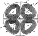
Preferably as shown in Figure 2, static field magnet assembly 12 comprises a plurality of cylindrical shape superconducting coils with respect to a central axis arranged concentric.In these coils, comprise an interior loop 28, a middle part coil 30 and an exterior loop 34 of arranging concentrically with respect to one another.One annular cryostat 36 is round these coils.Preferably as shown in Figure 1, cryostat 36 defines one and extends through interior loop 28 and around the endoporus 38 of axis 26.Cryostat 36 is toroidal shells made from nonferromugnetic material.This cryostat also comprises the cold-producing medium of liquid helium for example or liquid nitrogen and so on, so that each coil is maintained superconducting temperature.In a kind of known technology, each coil is bearing in the cryostat with the inner support (not shown).Though the wall of illustrated cryostat is a single wall, in fact cryostat preferably has one or more multiple wall constructions, promptly has the vacuum space between each wall.Such structure is also referred to as Dewar (Dewar) container, and it can make to the cryostat content conduction of heat minimum of (comprising coil and cold-producing medium).Perhaps, cryostat can be an insulating closure, and it can cool off with the means except that cryogen, for example by thermoelectric cooling or other refrigeration system commonly used.These systems can adopt the superconductor of high TC.
Illustrated among Fig. 3 and be used to represent the benchmark of each coil dimension and the framework that size is determined system.The average diameter of each coil or R mAnd radial thickness T rAll be that relative axis 26 is determined.Each coil axial arranged is the average axial dimension A by coil mProvide, this size begins to measure from the central point 22 of magnetic resonance volume and obtains.The axial thickness T of each coil aBe the size of coil on 26 directions that parallel to the axis.Coil also defines a frontal plane 40 perpendicular to axis 26 at the forefront of the coil in the foremost of static field magnet assembly.
The coil of Magnet 12 is connected in a power supply or a magnetostatic field exciting bank 33 (Fig. 1) commonly used.Device 33 can provide electric current to coil.Direction of current flow in each coil is shown in the arrow among Fig. 3 " just " or " bearing " symbol.These optional senses of current are reciprocal.Also show space before among Fig. 3 apart from f, in other words conj.or perhaps the distance of central point 22 from the static field magnet assembly to imaging volume 20.
The size of each coil that is used for Fig. 1,2 and 3 illustrated embodiments has been shown in Table I.
Table 1
Coil The sense of current The amp-number of turn Axial location A m(cm) Axial thickness T a(cm) Average diameter R m(cm) Radial thickness T r(cm)
Interior loop (28) Just 1,159,20 0 33.7 14 17.88 5.04
Intermediate coil (30) Negative 1,863,00 0 33.7 14 25.55 8.1
Exterior loop (34) Just 1,076,40 0 33.7 14 36.64 4.68
As above shown in the table, this Magnet can be by a less relatively linear axial magnetic field gradient
Figure C9880535900121
Provide the magnetic field of about 1 kilogauss for about 5cm, in the zone of the about 25-30cm of frontal plane at a diameter.In same zone, radial magnetic field curvature It is less also to compare, thereby radial magnetic field gradient is also less.This Magnet can be by the axial gradient of a linearity and very little gradient, is approximately 1cm, diameter at an axial dimension and is approximately in the magnetic resonance volume of 3cm or the imaging volume 20 and produces a magnetic field.The center of volume 20 drops on a little 22, and the spacing distance f of it and frontal plane 40 is about 26cm.This Magnet is less relatively; It is that about 78cm, thickness are only in the cylindrical space of about 14cm that each coil of Magnet can be contained in a diameter.So little size of Magnet can reduce cost and the weight and the running cost of cryostat greatly.According to the different materials that cryostat adopted, the weight of whole Magnet can be less than 500kg, thereby can move and with respect to patient location by a positioner 33 with reasonable size.
The gradient coil size
Fig. 4 shows gradient coil assembly 14.This gradient coil assembly comprises four windings 50,52,54 and 56, they are provided with around the coaxial line or the axis 26 of static field magnet, winding 50 and 52 has formed one along the relative paired winding of diametric(al), and winding 54 and 56 has formed another along the relative paired winding of diametric(al).Each winding roughly is planar, and is positioned at the plane perpendicular to the axis 26 of static field magnet substantially. Coil 50 and 52 is to be provided with the perpendicular first axle (being marked with " X " among Fig. 4) of the axis 26 of static field magnet 12 or Z-direction along one, and another is along with axis 26 or Z-direction is perpendicular and be provided with perpendicular to another axis (being marked with " Y " in Fig. 4) of the X-direction of winding 50 and 52 to winding 54 and 56.These windings are that the metal tape little with thickness, that width is big is made, and metal tape is such coiling, that is, the width of metal tape parallels to the axis 26 perpendicular to the coiling plane.For example, metal tape can be that about 0.016 inch (0.4mm) is thick, and about 0.75 inch (2cm) is wide.Each winding can comprise the such metal tape of about 120 circles.Winding 50 comprises that one is the outer arc segments 58 with axis 26 concentric arc form substantially, and comprises a pair of radial section 60 and 62 that extends radially inwardly from the end of segmental arc 58.These two sections are converged near axis 26.Other winding 52,54 and 56 comprises similar section.Because this static field magnet can apply a magnetic field gradient regularly on axial or Z-direction, thus the gradient coil assembly that this embodiment adopted do not comprise Z to gradient coil.Yet, if desired Z to gradient coil, it can be one with axis 26 concentric circular solenoids.
Each winding all is installed in the housing 57 of a nonferromagnetic, is provided with the refrigerating channel (not shown) that several are connected in a chiller or other cryogen source in this housing.Radius from the axis 26 of each winding to outer arc segments is about 25cm or littler, thereby the diameter of whole gradient coil assembly 14 and housing 57 has only about 50cm, and thickness has only about 3-4cm.
Housing 57 is provided with near the front portion of static field magnet 12,, just in time in the front of cryostat 36, and is positioned as close to the frontal plane 40 of static field magnet that is.So just the direction along axis 26 has stayed a very big space between gradient coil assembly and imaging volume 20, thereby makes the imaging volume can be positioned at the patient body dearly.Each winding of gradient coil assembly is connected in gradient drive 35.The hole that the energy supply and the control of gradient coil can be passed cryostat 36 is carried out.
The gradient activator comprises D/A converter commonly used and amplifier, is used to receive convert analog form to from one of computer 29 required digital gradient waveform, with this digital waveform and duplicate as the analog waveform by the electric current in the specific gradient coil of equipment computer control.In order in imaging volume 20, to apply the magnetic field gradient of a directions X, can be encouraged paired two windings, the interior electric current of outer arc segments of two windings is flowed along the axis 26 of opposite direction around the magnetostatic field assembly.For example, when winding 50 and 52 was subjected to the excitation of the electric current of direction shown in arrow C among Fig. 4, they can provide a magnetic field gradient on X-direction.Reverse electric current will produce gradient in contrast to this.Winding 54 and 56 can encourage in a like fashion, so that apply a magnetic field gradient on the Y direction.
HIFU device and RF system
Comprise a mechanical installation elements 62 (Fig. 5) at arm 17 front ends or terminal mount pad 19, for example the bellmouth shown in the figure or other device commonly used connect distribution structure so that form a releasable machinery.For example, bellmouth 62 can replace with anchor clamps, clamping element, screwed joint or grasping device, multijaw chuck or cartridge type chuck commonly used.Mount pad 19 also comprises a cold-producing medium service duct 63 and cold-producing medium extraction passage 64, and they are connected in cryogen source (not shown) commonly used, for example a cold water.Mount pad 19 also comprises a multicomponent electric connection 66, and this joint is connected in high-intensity focusing ultrasonic wave driver 41 (Fig. 1) successively.
Ultrasonic energy bringing device 16 comprise one can high-intensity focusing ultrasonic wave device 68.Device 68 comprises the framework 70 of a substantially rigid, and this framework is preferably used polymeric material, for example Merlon or epoxy resin or other comparatively inflexible high-strength polymer.Framework 70 has an installed part 72 that is rigidly connected thereon.Installed part 72 is suitable for forming a rigidity and releasable the connection with mounting receptacle 62 cooperations.For example, when mounting receptacle comprised a tapered socket, installed part 72 can be a pin with the taper that matches.Framework 70 has formed a tray, and this tray is roughly a convoluted surface around axis 74.
A plurality of ultrasonic emitting parts 76 are arranged to array on framework 70.Preferably as shown in Figure 6, each radiating portion 76 comprises a rigidity backing 78, for example piece of being made by aluminum, glass or rigid polymer.Radiating portion also comprises a piezoelectric membrane 80, and for example the trade mark of being produced by AMP Inc. of Pennsylvanian Harrisburg is the polyvinylidene difluoride film of Kynar.Between thin film 80 and backing 78, be provided with one group of rear electrode 82, and electrode 84 before on the front surface that deviates from backing 78 of thin film 80, being provided with a group.Before electrode and rear electrode match in pairs and be arranged to each preceding electrode all is overlapped in rear electrode.For example, electrode 82a and 84a have just formed a pair of.These electrodes are aimed at mutually, and overlapped.Though can only see three counter electrode in Fig. 6, radiating portion 76 can comprise a lot of counter electrode that are arranged in the array, for example, in one 3 * 3 array, can comprise 9 pairs.There is lead-in wire separately to stretch to each electrode.Electrode 82 and 84 preferably forms with the lip-deep thin electric conductor that is deposited on piezoelectric membrane 80, coating electrically conductive printing ink on the surface of piezoelectric layer for example, or by for example technology such as sputter or chemical plating, electroplate again subsequently.Each goes between and 86 stretches out from each electrode.
Each counter electrode and thin film 80 parts that are arranged between the paired electrode have formed a piezoelectric transducer that can work independently.By paired two electrodes are applied opposite voltage, just can make the thin film zone between these two electrodes expand or shrink towards forward or backward direction (be among Fig. 6 upper and lower to).Therefore, by applying the electromotive force of an alternation, just can under frequency of ultrasonic, drive the film portion between every counter electrode.Particular transmission shown in the figure partly has the rear electrode on the surface that directly is adhered to backing 78, thereby the rear surface of rear electrode and thin film is kept rigidly.Under this configuration, wish the thickness of thin film 80 is arranged near 1/4th of the wavelength of ultrasonic vibration.Common operating frequency is to arrive in the scope of 1.8Mhz about 1, and that the most common is about 1.5MHz, and the ultrasonic vibration wavelength in thin film is about 1mm.Therefore, when embodiment remained on the backing like that rigidly as shown in Figure 6 in the rear surface of thin film, the ideal thickness of thin film 80 was about 250 microns.In other embodiments, thin film is supported to and leaves backing, thereby the rear surface of thin film separates with backing, thereby it can freely be vibrated.In these embodiments, the thickness of thin film approximately is half of wavelength, preferably about 500 microns or bigger.The protective layer (not shown) of thin polymer film for example or sealant and so on can be set, so that they unlikelyly contact with environment on the front surface of thin film 80 and electrode 84.A ring 90 made from rigid materials such as aluminum or polymeric materials is extended around the periphery of thin film.Ring 90 is fixed in supporting member 78.
Radiating portion 76 is fixed in framework 70 (Fig. 5).The lead-in wire that links to each other with each electrode of all radiating portions is connected to multicomponent plug 94 by a common cable 92, and this plug is suitable for matching with the multicomponent socket 66 of mount pad 19.Each lead-in wire and cable are to adopt to be applicable to that frequency specification is that the standard technique of the electrical structure of 1.5MHz is constructed and formed.For example, be connected in the preferably co-axial twisted-pair cable of each root lead-in wire of every counter electrode, or other is suitable for the transmission line of high-frequency work.Cable 92 can also form so-called flexible circuit, and it can admit a lot of transmission lines.Each radiating portion 76 is installed on the framework, makes its front surface or the activated surface surface of electrode 84 (carry before) forward, i.e. downward direction in Fig. 6.So the front surface of each element of radiating portion has constituted a phased array (phased array) of ultrasonic transmitter.The energy that each ultrasonic transmitter sent can focus on the little focus 94.Preferably, this transmitter array preferably can provide a point that is of a size of about 2-3mm.When handle assembly was used for thermal ablation, this array preferably can provide an about 1500w/cm on focus 2Ultrasonic intensity so that in less than the time in 1 second, the tissue on the focal position is heated to 60-80 ℃ from about 37 ℃.Usually, must apply about 1500 watts electric power, to produce about 500 watts ultrasonic emitting to array.Described focus can be arranged on energy and apply on the interior a lot of positions of volume 21 scopes.Put on the phase place and the amplitude of the driving signal of each ultrasonic emitting element by change, that is, change the phase place and the amplitude of the signal of telecommunication that is sent to each electrode 82 and 84, just focus can be shifted out energy and apply outside the volume 21.
The transportable scope of the size and dimension of focus and focus depends on the positioned opposite and the characteristic of each emitter.Preferably, be arranged to provide the focal length of an about 20cm, that is to say that the distance that applies volume 21 centers along axis 74 from the array to the energy is about 20cm or bigger transmitter array.Usually, the diameter of transmitter array is about 15cm.Customized configuration discussed above only is exemplary.Therefore, various piece can be aforesaid flat, also can be crooked.Sweep can be spheric, perhaps also can have different radius of curvature along each axis.Each several part can be littler or bigger than discussed above.Say that terrifically each several part can include only an element.In another extreme example, whole array can be formed by a sweep, and the backing of this part can be used as framework 70.Each radiated element in the array and each radiated element in the single part can have different shape and size.For example, each radiated element can have square or other polygonal shape, perhaps can be circular or oval-shaped.Be published in " Int.J.Hyperthermia " Vol.7 in 1991 people such as Ebbini, #6, " optimization of many focus phase-controls array heating pattern intensity gain " on the pp.953-973; People such as Ebbini are at IEEE " about ultrasound wave, ferroelectric and FREQUENCY CONTROL " collection of thesis the 36th volume pp.540-548 (1989) " analysis-by-synthesis of many focus phase-controls array pattern: too high surmount the Optimum Excitation signal distributions that the body temperature treatment technology is used "; And people such as Fan is at " doctor " the 22nd volume (#3), in the articles such as " in non-intruding ultrasonic surgical operation process, the utilizing of the control of one 16 element phased arrays " of delivering on the pp.297-305 (1995), relevant ultrasonic phased array row have been discussed and to the computer simulation of these arrays to the slough volume.The content of these articles can be quoted at this with for referencial use.
But the device 68 of disposable also comprises the flexible bag 98 that fills up water, and this sack is attached to framework 70, makes the ultrasonic element on the framework be connected in water, so that ultrasound wave is transmitted entry.For example, sack 98 can be attached to the neighboring of framework 70.Sack 98 can be made with thin thin polymer film.For example, supporting in use by the sack surface of therapist health and can make, and other wall of sack can be made with polyethylene film with pet film.Water in the sack 98 does not preferably have dissolved air basically.If it is gas-pervious constituting the thin film of sack 98, but then preferably in the manufacture process of this disposable device air is removed, but and should be placed in the air-locked outer container with vacuum-packed form by the disposable device.But the disposable device also comprises a coolant channel 100, and it has and is suitable for connecing the coolant channel 63 of joining mount pad 19 and 64 joint 102 and 104.The member commonly used that is used to provide by the required driving signal of computer 29 instructions is provided HIFU driver 41 (Fig. 1).Driver 41 is connected in socket 66, thereby when cable 92 was connected in socket, the HIFU driver was connected in all electrodes 82 and 84 of piezoelectric element.
End at arm 17 is equipped with a flexible skirt 106, and it protrudes out downwards around mount pad 19 and from wall 17.Hoop antenna 37 is installed on the part away from arm 17 in skirt section.Transceiver generally includes one and has the radiating portion and a sensitive receptor of relative higher-wattage, and comprise be used for emitter start seasonal receptor by or start the device that seasonal emitter ends at receptor.RF antenna and transceiver preferably can be tuning in such frequency range, promptly and be used to be in the Larmor frequency or the corresponding frequency range of magnetic resonance frequency of the proton under the action of a magnetic field of static field magnet.Preferably, regulate on the ad-hoc location that is used in the imaging volume or tuning variable member, for example variable condenser or capacitor handover network all being provided with on generator or the receptor to be complementary with the Larmor frequency.
During use, but disposable HIFU device 68 is received in the skirt section 106, and it is cooperated with mount pad 19, thereby axis 74 with respect to HIFU, the HIFU device is positively remained on the arm 17, and described axis 74 extends downwards, and perpendicular to the axis 26 of static field magnet.In the case, energy applies volume 21 and imaging volume 20 overlaids.In addition, the HIFU device remains on the fixed position rigidly, and is orientated with respect to static field magnet.When this device was used to patient, the position of arm 17 preferably can allow water bag 98 contact patients' skin.Ultrasonic vibration can be sent from radiating portion 76, and passes to patient by water and sack itself in the water bag 98, and it loses minimum.Can on the surface of sack, apply gel or emulsifiable paste, so that the loss minimum of transfer of vibration.Loop aerial 37 be arranged on patient's body surface with interior or near.The axis of loop aerial is close with the axis 74 of HIFU device or aims at.In other words, the axis normal of loop aerial 108 is in the axis 26 of static field magnet, thereby perpendicular to magnetic vector.
Control station and control computer
Control station 13 comprises a common monitor 110 (for example a cathode ray tube or flat panel display) and a manual input device, and the latter comprises a stick 112 (Fig. 7) and a knob 114.Stick 112 is so-called " force feedback " stick preferably, is furnished with the usual means that can respond the instruction that lever assembly receives and stick be applied power.The proper control bar can be the product that Microsoft company sells with SidewinderForce Feedback Pro trade mark.Knob 114 can be combined in the lever assembly.Stick has also been equipped a button 115.
Control station also comprises additional instruction and gauge tap 116, and comprises a keyboard (not shown).All these elements all link with control computer 29.Control computer 29 (Fig. 1) is a general digital computer preferably, for example is commonly referred to as the computer of " work station " type, and comprises for example common component of microprocessor and transfer data bus (not shown) and so on.Control computer also comprises memory element 118, and it can be in conjunction with dynamic RAM for example, wipe usual means and for example mass storages of optional memorizer of disk and so on such as memorizer soon.The data/address bus of control computer is connected to each element, localizer interface, magnetostatic field bringing device 33 and gradient drive 34 and the HIFU driver 41 and the RF transceiver 39 of control station by an interface element (not shown) commonly used.Wish the program of control computer is arranged to show a following described mode of operation menu on monitor 110, so that make the operator select required mode of operation by switch 116.
Operation
In method according to an embodiment of the invention, a patient P (Fig. 1) is supported on the bed 24.Movable device 10 relies on castor 27 to move on the position, makes magnetic resonance volume 20 and energy apply the organ 120 of volume 21 rough alignment patients' needs treatment.The water bag of HIFU device and patient's contact skin, RF antenna 37 is around the water bag location.The operator can operate computer and carry out a preliminary nuclear magnetic resonance operation.So the same with the order of the nuclear magnetic resonance of routine, static field magnet is activated and applies magnetic field in magnetic resonance volume 20, gradient coil and RF transceiver are activated and apply RF signal and magnetic field gradient.By the atomic nucleus in main magnetic field in certain the thin slice S (Fig. 3) in the magnetic resonance volume 20, preferably proton can arrive the frequency tuning of transceiver 39 and antenna 37 corresponding with the Larmor frequency.Because upwards there is gradient in the magnetic field that provided by static field magnet at axial or Z, and since nuclear larmor frequency change with main field with being directly proportional, so resonate or the Larmor frequency along with changing along the variation of the distance of Z-direction.Encourage gradient coil in a conventional manner, and on the X of perpendicular to axial direction or Z-direction and Y direction, apply magnetic field gradient.This will cause changing in a kind of known mode from the frequency of the atomic nucleus signal of each position in the thin slice and phase place.The RF transceiver is activated and receiving magnetic resonance signals, makes this signal digitalized, and gives control computer 29 with digitized signal provision.This process repeats in a kind of known mode by means of the gradient of X and Y direction.The signal that transceiver 39 is gathered is stored in the memorizer of computer.Computer can utilize one of known program restructuring be positioned at thin slice S by the image of therapist.This program can utilize different radio frequencies to carry out repeatedly, uses the different thin slice of selection in magnetic resonance volume 20.Final synthetic data can provide be positioned at the magnetic resonance volume by the 3-D view of the part of therapist.
This pictorial display is on monitor 110.The operator can observe this image, and whether being centered within sweep of the eye by area for treatment of definite patient.As shown in Figure 7, this image can be shown as by by the pair of orthogonal profile of therapist health.Zhi Liao zone is not centered within sweep of the eye if desired, and the operator just can import an instruction to control computer, reorientates pattern to enter one.Under this pattern, computer can receive the input signal from stick 112 and knob 114.Therefore, according to the order that receives from instruction input element 116, control computer will be translate into the instruction that makes chassis 15 translations or rotation from the input signal of stick 112 and knob 114.For example, computer settings can be become can receive the translation input signal, and stick is used as along X ' direction mobile is to make the make progress instruction of translation of chassis, is the instruction that makes chassis level move with stick along mobile being used as of Y ' direction, and with knob 114 mobile be used as be make before and after the chassis or Z to the instruction of translation.After other instruction that receives from instruction input element 116, computer can be used as stick along X ' direction mobile be to carry out the instruction of elevating movement around one perpendicular to the horizontal axis of axis 26, and with stick along laterally mobile being used as of Y ' is to make the chassis center on the instruction that a vertical axis rotates.Imaging process is carried out repeatedly, the image on operator's persistent surveillance display.When the operator observed image, he or he can utilize this image to diagnose the intravital situation of people, for example detected the intravital infringement of people that needs treatment.When the organ that needs in the health to treat or zone have been centered within sweep of the eye, the operator can send another signal to instruction input element 116, make control computer lock this position, and chassis 15, static field magnet, HIFU device and the locking of other element are put in place.Therefore, TMR's reference frame of being set up by static field magnet and associated components can be fixed up.
In the case, will to be used as from the input signal of stick 112 and knob 114 be the instruction that allows a theory target point in this fixed TMR frame move to computer.Therefore, when stick when the direction of X ' and Y ' moves, theory target point changes its position along X and Y direction respectively, and the rotation of knob 114 will cause the theory target point to move on the Z direction.One cursor 124 is presented in the image on the monitor 110 one and puts on the corresponding position with theory target.The operator can move to cursor 124 on a series of summits 126 by knob and stick.The operator can be selected and constituted a polyhedron these summits, or surrounds the polyhedron group of the area for treatment that needs heating.In example shown in Figure 8, this pictorial display infringement L.Summit 126 is chosen to form a pair of frusto-pyramidal 128a and 128b, and they have surrounded this infringement L jointly.When the operator moved to cursor on each required point, he sent another instruction by pressing the button 130 on the stick 112 to control computer.Computer will be recorded in the memorizer 118 corresponding to the theory target point on each summit.Computer also produces a polyhedral line frame graph picture on indicator screen 110, and with this image overlay in produce by magnetic resonance information by the image of therapist.
At next procedure, but the computer activation energy applies or HIFU device 16, applies the ultrasound wave of focusing on a point 94 corresponding to one of each summit 126 position.Computer command HIFU driver applies the energy of less relatively " limit value is a following " dosage to the tissue of putting 94 places.That is to say that the energy that the HIFU driver is provided is chosen to heat that this operation applies and can does not damage or change tissue.For example, for human body, tissue should be heated to about 40 ℃ from normal body temperature (37 ℃).In theory, because position and the orientation of HIFU device on TMR's reference frame is known, and, thereby should be positioned at truly on the position of being instructed by focus by computer 29 owing to the position of point 94 is to change along with the variation that is offered the HIFU signal by HIFU driver 41 in a kind of known mode.In fact since the precision of equipment is not enough and organization of human body to the refraction of ultrasonic energy, computer 29 is instructed is subjected to the hotspot location and the actual hotspot location that is subjected to that some deviations are arranged.After the energy that has applied the following dosage of limit value, repeat imaging process by a thermally sensitive magnetic resonance order (for example T1 weighting order), make shown image comprise that an expression is subjected to the point 94 ' of focus.Subsequently, the operator can navigate to a little 94 tops with cursor 124 by stick 116 and knob 114, and controls input signal for button 115 provides another.Therefore, computer can get off the location records corresponding to cursor and as the actual focus that is subjected to.Subsequently, computer deducts the coordinate of the location of instruction on the coordinate of physical location.The result who is obtained is exactly a correction vector.In ensuing operation, computer is revised vector with this and is added on all new locations of instruction, and using provides a revised location of instruction, so that heat on the real location of instruction.
In case obtain to revise vector, computer just can be carried out a test point order.In the test point order, computer command HIFU device makes each summit as a test point at the energy that each 126 place, summit applies the following dosage of a series of limit values.When applying the following dosage of limit value, computer can order the HIFU device summit or test point to be applied the energy of specific size.Before or after applying the following dosage of limit value, can start magnetic resonance equipment and determine temperature on each test point.Computer can write down the size (normally measuring the input power that is supplied to the HIFU device) of the energy that is applied by the HIFU device and the temperature that causes in memorizer 118 raises.About this point, MR imaging apparatus need not to finish whole imaging and measures temperature in proper order.On the contrary, magnetic resonance equipment can activate to gather from the signal volume element of the test point of being heated or the magnetic resonance signal of " voxel " with a kind of known mode.Be published in " biomedicine " 1982 at Mansfield and Morris, described so-called " sensitive spot " magnetic resonance method in the article of P.98 going up " NMR imaging ".Monitor by parameter (for example spin lattice T1 slack time) the magnetic resonance signal that changes with tissue temperature, computer can monitor be heated summit or test point 126 places by the temperature of the tissue of therapist.Computer can according to note the energy of executing and temperature rise calculate the energy of executing with respect to the calibration curve of temperature rise.Under the simplest situation, computer can only calculate the slope of a linearity curve of the temperature rise-energy of executing.
In case obtained the calibration curve on all summits, the operator just can operate computer and enter a treatment pattern.Computer command HIFU device applies energy to the tissue by therapist that is in treatment volume or the polyhedron 128.Computer command HIFU applies is enough to therapeutic dose that the tissue on each treatment position is heated, so that carry out required treatment.When treatment comprises thermal ablation, therapeutic dose can be chosen as the temperature that can make tissue and reach more than 43 ℃, reach 60-80 ℃ usually.Other treatment for example in order to strengthen the effect of medicine or radiotherapy, is adopted lower temperature usually.The size that is applied to the energy of each treatment position is to select according to the calibration curve of an interpolation.Therefore, can be by in the middle of the calibration curve of the test vertex that is used for polyhedron treatment volume, carrying out the calibration curve that linear interpolation is calculated each treatment position.For example, this computer can calculate each treatment position and surround distance between polyhedral each summit of this treatment position, calculates a weighted mean slope S according to following formula more subsequently Ave
S ave = Σ i = 1 i = n s i d i Σ i = 1 i = n 1 d i
Wherein:
S iBe i ThThe slope of individual summit or test point; And
d iBe from the treatment position to i ThThe distance of individual summit or test position.
When treatment position overlaps and makes apart from d with test point iWhen being zero, computer is with S AveBe set at the slope that equals test point or place, summit.For example, treatment position 136a is near test point or summit 126a, away from test point or summit 126b.Computer can be set at the slope at the treatment position 136a place on energy-temperature rise curve the slope at points of proximity 126a place.Computer can automatically be selected new treatment position, calculate the slope of the treatment position of newly electing, and apply suitable therapeutic dose, up in the treatment volume that limits by polyhedron 128a and 128b, all having applied described therapeutic dose on all possible treatment position.Preferably, can make each treatment position in 1 second or shorter time, promptly reach temperature required.So system just can finish treatment apace in whole treatment volume.
In applying the process of therapeutic dose, computer can be gathered the magnetic resonance information from the one or more voxels of treatment in the volume, and monitors temperature in the voxel according to this magnetic resonance information.Perhaps, computer can be set by a thermally sensitive imaging, activates magnetic resonance equipment and carries out an order of nuclear magnetic resonance completely, and show the image of heat affected zone and surrounding tissue on display.After finishing whole treatment, the operator can command system gather a new magnetic resonance image (MRI), so that obtain therapeutic outcome.
In another process, the operator can come mobile theory impact point applicator by stick 112 and knob 114, thereby cursor 124 (Fig. 8) is moved in the image that shows in mode discussed above, and presses the button 115 to mark summit 126 '.Yet computer is instructed noting of regional summit avoided as one in these summits, rather than the summit of treatment volume.Computer is in aforesaid mode, by a line frame graph picture that produces polyhedron 128 ' corresponding to the summit on summit 126 '.The operator can select summit 126 ' by the image that observation post shows, and then selects by avoiding the tissue that the zone surrounds.In the example that Fig. 9 executed, on monitor scope 110, show a sensitive structure, for example the image of urethra U.The operator can set up this avoidance zone, to surround urethra.Computer will be noted as the polyhedron border of avoiding the zone boundary.The test point 129 that select to avoid outside the zone operator artificially is also carried out aforesaid calibration steps, so as calibration system about the aligned error of HIFU, and the heating calibration curve of each test point 129 obtained one execute dosage.Repeat, each test point preferably is chosen as and they is in or the close border that needs the infringement L ' of treatment.
Subsequently, the operator can import an artificial Investigation of Ablation Mode.Under this pattern, the operation that computer can respond stick 112 and knob 114 comes the impact point of mobile HIFU device, and computer can respond the startup of button on the stick and apply a therapeutic dose on current target point.For example, when cursor 124 was positioned at the image range of infringement L ', the theory target point was positioned at infringement.Applying a therapeutic dose just can be being heated tissue on the intravital point by therapist corresponding to impact point.This dosage can perhaps can be selected the artificially according to automatically selecting with respect to the dosage of aforesaid heating calibration curve.If the operator attempts this impact point is moved in the avoidance zone, system can prevent that him from doing like this.Therefore, when impact point moves into impact point when avoiding the zone near avoiding zone and operator's command system, system will can not do like this.On the contrary, system will be by providing force feedback to send warning signal by control device.For example, when cursor is arranged in 124 ' the position of Fig. 8, moving up along directions X will cause cursor to enter avoiding the zone.If the operator attempts to make stick 112 to move up along directions X, and then cursor 124 ' is moved up, then system will apply a balancing force feedback to revolt this motion.Force feedback can provide the intuition warning of a uniqueness to the operator.Yet, also can adopt the caution signals of other form.For example, system can show an alphanumeric warning on monitor 110, perhaps can make the monitor scope flash of light, perhaps can make cursor be special color.Also can adopt the mode of audible alert.
In the another kind variation pattern of this system, computer can allow the operator that impact point is moved into the avoidance zone, but can prevention apply a therapeutic dose when impact point is positioned at the avoidance zone.Same is that when the operator attempted to apply a therapeutic dose when impact point is positioned at the avoidance zone, system can show the warning of any form in sense of touch, vision or the audition.
In method discussed above, only be the magnetic resonance information of in a magnetic resonance volume, gathering.Yet magnetic resonance information can be collected by this system in a plurality of different magnetic resonance volumes.For example, as shown in Figure 3, static field magnet can swing to a new orientation so as to making axis 26 ' around vertical axis swing with relevant member, and the magnetic resonance volume is moved on 20 ' the reposition that is illustrated by the broken lines.Therefore, by mobile chassis and static field magnet and the associated components that is mounted thereon, just can set up different TMR's reference frame.Computer can write down chassis moving between these positions.Therefore, each new TMR's reference frame is on a known position and the orientation with respect to all former TMR's reference frame.The magnetic resonance information that accumulates in all each reference frame can be delivered in one, the common benchmark job frame.Under this mode, system can show the feature of having surrounded in the relatively large zone by the therapist image.Because HIFU device 16 is installed on the same chassis with static field magnet, thereby the reference frame of HIFU device is maintained fixed with respect to the reference frame of static field magnet.So, to being treated, can move to then on the new position when system can be on a certain position on the chassis being treated by another locational tissue in the therapist body by therapist.In fact, computer can be constructed the insert of a less relatively magnetic resonance image (MRI) so that this insert can whole encirclement by big zone of therapist.
The shape of gradient coil can be the shape except that the above shape of discussing in conjunction with Fig. 4.For example, X and Y gradient coil can be round.Also have, when static field magnet can not be regularly vertically or Z when a magnetic field gradient is provided, another one or a plurality of coil can be set.For example, the Z gradient coil can comprise an endless solenoid coaxial with the axis of static field magnet.
In yet another embodiment, the X gradient coil can form the pair of saddle-shaped coil 202 (Fig. 9 and 10) that is arranged in 226 both sides, static field magnet axis.Preferably as shown in figure 10, each X gradient coil 202 has the segmental arc 205 that roughly extends around the axis along the elongated segment 203 and the part of the extension of axis direction.Segmental arc is along the X-direction space of magnetic resonance reference frame.As shown in Figure 9, gradient coil assembly can comprise a pair of similarly along the saddle coil 204 of Y direction space.Be arranged on the place ahead of cryostat at the segmental arc of the X of coil front end and Y gradient coil, the centre bore that elongated straightway then passes cryostat extends back.Can see that on the end view of seeing along axis 226 X and Y gradient coil are partly overlapping.Change in the pattern at another, the elongated segment of saddle coil can be extended in the outside of cryostat.
In another changed pattern, X was elongated to gradient coil 210 (Figure 11) on the Y direction, thereby these coils can apply the gradient of a directions X in the relatively large elongated imaging region of Y direction size.Y separates distantly to gradient coil 212 relatively, thereby these coils also apply the gradient of Y direction in same elongated imaging region.Gradient coil can be of different sizes.For example, X can be of different sizes to gradient coil 212.
In order to replace the HIFU device of aforesaid phased array, the HIFU device can have a fixed focus, arm 17 or mount pad 19 (Fig. 1) can be that movable joint connects, thereby the HIFU device is moved with respect to chassis 15 by the axis 74 of tuning HIFU device 16, just can move hyperacoustic focus.In another changes pattern, articulated arm 17 ' or the installed part 19 ' that is supporting HIFU device 16 ' can be combined with phased array.Articulated arm 17 ' has a relevant positioner 23 ', thereby HIFU device 16 ' can change with respect to the location and the orientation on chassis 15 '.Yet position and the orientation of HIFU device 16 ' in the TMR's reference frame that is limited by static field magnet remains known state.This method allows operator (for example the position 16 " and 16 ) on all directions to guide ultrasonic energy to enter by in the therapist body, to avoid influencing organization of human body.Control computer can show that an expression energy applies the labelling of 21 ' center, zone, moves to desired location so that the operator applies the zone with energy on by the image of therapist.
Change in the pattern at another, several ultrasonic transducers can be installed on the deformable flange, this flange can be out of shape selectively by an actuator, and with the focus of change ultrasonic transducer, and then adjusting is to the focus of desired location.Perhaps, each transducer is pivotably mounted on the apparatus frame, and the pivot installed part interconnects, thus each transducer can be together to towards or the direction of leaving the HIFU axis pivot.In another change type embodiment, the HIFU device can comprise be arranged on one with the co-axial array in static field magnet axis in ultrasonic transducer, described array can be for example around the loop configurations of magnet assemblies front side.In a kind of like this configuration, the ultrasound wave axis is coaxial with the axis of Magnet.Similarly, ultrasonic transducer can be installed on a deformable flange or the moving element, thereby the focus of ultrasonic energy can be regulated.
In another changed pattern, ultrasonic transducer or HIFU can replace with other device that is used to apply energy, so that tissue on certain point in the calandria.For example, can utilize one to be used to apply the system that focuses on radio frequency (RF) energy.This RF system can install with the magnetic resonance member.Change in the pattern at another, the FR energy of focusing can be provided by the same emitter and the antenna that are used for the magnetic resonance operation.
In disposing as discussed above, when navigation system moved instrument chassis, energy applicator was along with Magnet moves with respect to patient together.In a change type configuration (Figure 13), an energy applicator is installed on the navigation system 318, and will comprises that the magnetic resonance equipment 321 of static field magnet is installed on the navigation system of separating 323.These two navigation systems are all by guide rail 325 supportings that are installed in the top, so that the operator moves each member in the room.When using this equipment, in the step that a positioning step with magnetic resonance device separates, make energy applicator with respect to being located by therapist.Yet similarly, energy applicator is that the tissue that is positioned to apply in the zone 321 energy that is in the magnetic resonance device visual field heats, and aims at the body structure that needs treatment.If activate heater at positioning stage, then can utilize magnetic resonance device to help the location, so that the some heating of heater can be positioned in the magnetic resonance image (MRI), can detect by magnetic resonance device in other words.Perhaps, computer can be arranged to show that an expression is superimposed on the sign that is applied the central point in zone by the energy of therapist image.Only preferably include the following dosage of the limit value of organizing mild heat at the activation means that position fixing process adopted, and can not cause nonvolatil injury tissue.
Preferably, navigation system 323 and 318 being arranged to can tracking magnetic resonance equipment 312 and position and the orientation of energy applicator 316 in a common reference frame.Make magnetic resonance equipment 312 and the energy applicator 316 mutual aligned steps can be by making energy apply mutual intersection of zone 321 and magnetic resonance volume 320 according to partially or even wholly carrying out by the data that navigation system provided.
One or more navigation systems can utilize the known technology in the orientation sensing technology to aim at patient's reference mark or anatomic landmark, and the imaging data of gathering before can writing down, and for example define the MRI or the CT data of patient's 3-D view.For example, one probe 330 can be connected in a position detector 332, this detector is suitable for providing probe terminal position (TMR's reference frame) in the reference frame of magnetic resonance device 312, or it has position in another wire frame of known relation at one with the TMR reference frame.The view data of Cai Jiing comprised in the past: the image 332 ' of the identification point 332 on the patient body, described identification point can be abiogenous anatomical features, and for example outstanding bone swells or was attached to by the reference mark of therapist before gathering imaging data.Touch identification point 332 by 330 the end of will popping one's head in, the operator can input to control computer with these positions in TMR's reference frame.By the cursor on the monitor of the image of collection before showing is controlled, the operator can be input to these points in the reference frame of former acquisition of image data, till this cursor is aimed at identification point.In case computer has had the position of the identical point in two reference frame, it just can utilize known technology to change between these two reference frame.
In case conversion is known, just can come the data that magnetic resonance device 312 is gathered are replenished with the view data of former collection.For example, in the positioning step of magnetic resonance and heater, the representative of the impact point of these devices can be identified on the display of images acquired before showing, they can be mobile like this, that is, device is moved up to each impact point is aligned on the zone that needs treatment with respect to patient.Can adopt uses the same method aims at a separate unit instrument that has MR and heating efficiency concurrently.
In a kind of modification of this method, movable magnetic resonance device is not used to gather the image by therapist.On the contrary, this movable magnetic resonance device only is used to gather the MR data of the single voxel on the interior known location of TMR's reference frame, so that monitoring heating process.So movable magnetic resonance equipment can be used in applying the process of proof load or apply in the process of therapeutic dose, to monitoring with the temperature of the single voxel in focus of energy applicator.Discussed above such as limiting the treatment volume or avoiding regional operation and can carry out with essentially identical mode; The image that the operator is shown is to come according to the view data of gathering in the past.If need not this movable magnetic resonance device imaging, just can relax requirement greatly, thereby reduce the size and the cost of equipment greatly such as aspects such as magnetic field uniform thickness gradient linearities to Magnet.This method depend in therapeutic process, remain on the fixed position by therapist.In a kind of modification of this method, can follow the tracks of by a therapist sign on one's body, so that to being moved forward into line trace and compensation by therapist.Such sign compensation scheme can also be used for the occasion of movable magnetic resonance device in order to images acquired.
In each above-mentioned preferred embodiment, the Magnet of magnetic resonance equipment is an one-sided moving-magnet.Also can adopt other moving-magnet.For example, specific movable superconducting magnet is used for nuclear magnetic resonance.These Magnet have the twin coil that is installed on a movable framework, so that will be arranged between the coil by therapist.In addition, though when described process be when in a traditional fixed magnetic resonance Magnet, carrying out, also can practical application test point of the present invention, treatment volume and avoid the content of aspects such as zone.
In the above-described embodiments, can do the focus of HIFU device or other energy applicator as much as possible little, so that accurately treat.In the method for another embodiment according to the present invention, energy applicator remains and focuses on the less relatively focus.Yet when applying energy, focus can inswept bigger " a pseudo-focus area " (below be called " PFR ").The size of PFR is usually greater than focus area.For example, the size range of PFR can be about about 1cm.Can scan with a part and be heated to temperature required or be higher than temperature required whole PFR or PFR.It would be desirable that PFR reaches temperature required part and can almost reach this temperature simultaneously.In scanning process, but focus is mobile in PFR with a repeat patterns or pseudo-random patterns, so that heat the diverse location in the PFR one by one.Each position that is heated one by one needs not to be successive or even needs not to be adjacent one another are.Therefore, focus can be jumped in PFR, gets on the point of opening very much thereby make focus can be positioned at PFR one by one.For example, focus can be moved with the pattern 404 of a raster-like all over PFR 402a, and adjacent spots is heated one by one.
By control each locational lotus admittedly than, just can control the average energy that puts on each point in the PFR.The same with pseudo-focus area, term " lotus admittedly than " is meant in the time that applies energy on the specified point shared ratio in whole heat time heating time.For example, if to focus area scanning of PFR 5 minutes, to surround the time of an ad-hoc location be 5 seconds to focus in these 5 minutes, and then the lotus of this point is admittedly than being exactly 1/60 or about 1.6%.In the scope of PFR, lotus is admittedly than not necessarily uniform.For example, when a spheric PFR being heated to equably more than the threshold temperature and when making all parts of this PFR almost reach this threshold temperature simultaneously, can recently handle admittedly with a lotus that is lower than the PFR outside, so that the faster heat loss of compensation from described outside to surrounding tissue to the center of PFR.For example, position 406b lotus admittedly than the lotus that is lower than position 406a admittedly than.Perhaps, the Mean Speed that each point of PFR is applied energy can be heterogeneous,, changes the energy that puts on focus that is, makes the energy level on the different focal positions in the PFR inequality.In addition, the tooth book of focus can change, and, regulates HIFU device or other energy applicator that is, to change the energy density (w/cm of the tissue in focus along with moving of focus area 2).
PFR can have different shape, for example spherical, oval, shaft-like, essentially rectangular, or the like.Usually, the shape of PFR can be chosen to make PFR to become " the simple connection " zone.In this article, term " the simple connection " is meant such zone, that is, for any two points in this zone, a straight line that connects these two points is in this zone fully.Aforesaid shape is exactly simple the connection.On the contrary, annular is not simple connection just.
Energy input in the whole PFR scope can calculate like this,, each the locational temperature in the monitoring PFR, for example measures magnetic resonance temperature on one or more points in the PFR that is, and perhaps gathering can be with the successive MRI reflection or the image of pictorial display.By the information that obtains in heating cycle, can carry out artificial or control automatically to heating process, be input to each regional energy size of PFR with change, and when the All Ranges of PFR has all reached required threshold temperature, stop heating process.When each zone reaches temperature required respectively, can stop the interior heating of zones of different of PFR selectively.For example, when temperature required be when being enough to the threshold temperature of kill tissues, heating process can reach this threshold temperature along with each zone of PFR and stop.Perhaps, can predict by aforesaid each test point and control heating process.
Can control the position of PFR with identical with above-mentioned focal point control basically mode.For example, by computer-controlled, can prevent from the avoidance zone that comprises responsive anatomical structure is produced in the system of thermal ablation, can by Control Computer stop to avoid the eclipsed any PFR in zone and apply energy.Also have, in the above system of discussing in conjunction with Fig. 7, when the user applied geometric coordinate to the volume of need treatment, the operator who controls this process or computer can select one or more its shapes and the PFR regional well matched that needs thermal ablation.For example, as shown in figure 14, the operator has defined one and has surrounded the treatment volume 400 that needs treatment patient zone.Subsequently, the operator can limit one group of PFR402 that is filled in this treatment volume.The operator can be with the border input computer of PFR, and its input mode is identical with the mode of input treatment volume.Subsequently, but computer activation energy applicator heats each PFR.
Owing to can under the situation that does not depart from the scope of the invention, adopt these and other modification and the combination thereof of above-mentioned feature, thereby should only play illustration, not limit the scope of the present invention that is defined by the following claims to the above description of preferred embodiment.

Claims (12)

1. therapeutic equipment comprises:
(a) static field magnet, it is suitable for applying a magnetostatic field on respect to the precalculated position in the magnetic resonance volume of this static field magnet;
(b) an energy applicator, it be suitable for an energy with respect to this applicator apply the zone in the precalculated position on apply energy;
(c) positioner, be used for moving described static field magnet and described energy applicator and both are located, so that described magnetic resonance volume is surrounded at least in part need treatment by the therapist zone, and make energy apply zone and described magnetic resonance volume to intersect mutually in by the therapist zone described.
2. equipment as claimed in claim 1, it is characterized in that, described therapeutic equipment also comprises a chassis, described static field magnet and described energy applicator are installed on described chassis, described positioner comprise be used to make described chassis move with allow described chassis with respect to described by the localized device of therapist.
3. equipment as claimed in claim 2 is characterized in that this equipment also comprises the gradient coil that is installed on described chassis, and described gradient coil can apply a magnetic field gradient in described magnetic resonance volume.
4. equipment as claimed in claim 3, it is characterized in that, this equipment also comprises: be used to activate described gradient coil to apply the device of described magnetic field gradient, and the radio-frequency transmissions/receiving system that is used to apply radiofrequency signal, this radio-frequency transmissions/receiving system can make and be sent magnetic resonance signal by the therapist tissue in the described magnetic resonance volume, and receives described magnetic resonance signal.
5. equipment as claimed in claim 4 is characterized in that, described equipment also comprises the device that is used for the magnetic resonance information for the image of being organized by therapist of the TMR's reference frame in the described magnetic resonance volume that draws from described magnetic resonance signal.
6. equipment as claimed in claim 4 is characterized in that, this equipment also comprises the device of the one or more locational temperature of being organized by therapist that is used for drawing TMR's reference frame in the described magnetic resonance volume from described magnetic resonance signal.
7. as claim 5 or 6 described equipment, it is characterized in that, this equipment also comprise be used in described TMR reference frame and the existing graphic based frame of the image of collection before by therapist between draw the conversion of a conversion-draw device.
8. equipment as claimed in claim 7, it is characterized in that, this equipment also comprises position detecting device, is used for determining the position of described static field magnet in a fixed reference frame, and described conversion-draw device can be at least in part draws described conversion by the detection position of described static field magnet.
9. equipment as claimed in claim 3 is characterized in that, described static field magnet is an one-sided Magnet, thereby described magnetic resonance volume is arranged on the outside of described static field magnet, and separates with described static field magnet along direction forward.
10. equipment as claimed in claim 8, it is characterized in that, this equipment comprises that also a visual display unit and can be with one by the display driver of the pictorial display of therapist on described display, and described display is installed in the position that is positioned at described static field magnet rear on the described chassis.
11. equipment as claimed in claim 1, it is characterized in that, described energy applicator comprises a ultrasound transmitting transducer array and a flexible fluid container that is installed in described ultrasound transducer array the place ahead, and described flexible fluid container can be engaged in described transducer array and by between the therapist body surface.
12. equipment as claimed in claim 11 is characterized in that, described energy applicator comprises a mount pad, and described transducer array and described flexible container are separable with respect to described mount pad.
CNB988053594A 1997-05-23 1998-05-22 MRI-guided therapeutic unit and method Expired - Lifetime CN1230120C (en)

Applications Claiming Priority (10)

Application Number Priority Date Filing Date Title
US4752697P 1997-05-23 1997-05-23
US60/047,526 1997-05-23
US5412497P 1997-07-28 1997-07-28
US60/054,124 1997-07-28
US6251897P 1997-10-17 1997-10-17
US60/062,518 1997-10-17
US7447498P 1998-02-12 1998-02-12
US60/074,474 1998-02-12
US7532498P 1998-02-20 1998-02-20
US60/075,324 1998-02-20

Publications (2)

Publication Number Publication Date
CN1257414A CN1257414A (en) 2000-06-21
CN1230120C true CN1230120C (en) 2005-12-07

Family

ID=27535001

Family Applications (1)

Application Number Title Priority Date Filing Date
CNB988053594A Expired - Lifetime CN1230120C (en) 1997-05-23 1998-05-22 MRI-guided therapeutic unit and method

Country Status (8)

Country Link
US (4) US6128522A (en)
EP (1) EP0998217B1 (en)
JP (1) JP2002505596A (en)
CN (1) CN1230120C (en)
AT (1) ATE419789T1 (en)
AU (1) AU8053598A (en)
DE (1) DE69840444D1 (en)
WO (1) WO1998052465A1 (en)

Cited By (4)

* Cited by examiner, † Cited by third party
Publication number Priority date Publication date Assignee Title
WO2008028354A1 (en) * 2006-08-25 2008-03-13 Beijing Yuande Bio-Medical Engineering Co., Ltd. Permanent magnetic resonance image-guided vitro high intensity focused ultrasound system and method
WO2010102582A1 (en) * 2009-03-13 2010-09-16 北京汇福康医疗技术有限公司 Ultrasonic fat reducing and body shaping machine
CN101495035B (en) * 2006-07-31 2011-04-20 国立大学法人冈山大学 Magnetic field generator and nuclear magnetic resonance device provided with this magnetic field generator
CN106659908A (en) * 2014-07-02 2017-05-10 泰拉克利昂公司 Therapeutic treatment device

Families Citing this family (378)

* Cited by examiner, † Cited by third party
Publication number Priority date Publication date Assignee Title
US6084587A (en) * 1996-08-02 2000-07-04 Sensable Technologies, Inc. Method and apparatus for generating and interfacing with a haptic virtual reality environment
US9198635B2 (en) 1997-10-31 2015-12-01 University Of Washington Method and apparatus for preparing organs and tissues for laparoscopic surgery
JPH11267133A (en) * 1998-03-25 1999-10-05 Olympus Optical Co Ltd Therapeutic apparatus
US6421048B1 (en) 1998-07-17 2002-07-16 Sensable Technologies, Inc. Systems and methods for interacting with virtual objects in a haptic virtual reality environment
US6552722B1 (en) * 1998-07-17 2003-04-22 Sensable Technologies, Inc. Systems and methods for sculpting virtual objects in a haptic virtual reality environment
JP2000107151A (en) * 1998-09-30 2000-04-18 Toshiba Corp Magnetic resonance imaging apparatus
US7844319B2 (en) 1998-11-04 2010-11-30 Susil Robert C Systems and methods for magnetic-resonance-guided interventional procedures
US6701176B1 (en) 1998-11-04 2004-03-02 Johns Hopkins University School Of Medicine Magnetic-resonance-guided imaging, electrophysiology, and ablation
US8244370B2 (en) 2001-04-13 2012-08-14 Greatbatch Ltd. Band stop filter employing a capacitor and an inductor tank circuit to enhance MRI compatibility of active medical devices
US6246896B1 (en) * 1998-11-24 2001-06-12 General Electric Company MRI guided ablation system
US6208142B1 (en) * 1998-12-07 2001-03-27 Transurgical, Inc. Magnetic resonance apparatus and methods with shim adjustment
US6278351B1 (en) 1999-01-11 2001-08-21 Transurgical, Inc. Multi-coil MRI magnet
IT1309458B1 (en) * 1999-02-10 2002-01-23 Paramed S R L MAGNETIC RESONANCE TOMOGRAPH APPARATUS.
US6508774B1 (en) 1999-03-09 2003-01-21 Transurgical, Inc. Hifu applications with feedback control
US6591127B1 (en) * 1999-03-15 2003-07-08 General Electric Company Integrated multi-modality imaging system and method
WO2000057495A1 (en) 1999-03-22 2000-09-28 Transurgical, Inc. Ultrasonic transducer, transducer array, and fabrication method
US6422552B1 (en) * 1999-07-26 2002-07-23 Heidelberger Druckmaschinen Ag Movable folders and former board arrangement
EP1229820A4 (en) 1999-09-10 2008-07-23 Prorhythm Inc Occlusion of tubular anatomical structures by energy application
FR2798296B1 (en) * 1999-09-13 2002-05-31 Centre Nat Rech Scient ASSEMBLY FOR HEAT TREATMENT OF BIOLOGICAL TISSUES AND METHOD FOR IMPLEMENTING SAME
US7520856B2 (en) 1999-09-17 2009-04-21 University Of Washington Image guided high intensity focused ultrasound device for therapy in obstetrics and gynecology
US7510536B2 (en) * 1999-09-17 2009-03-31 University Of Washington Ultrasound guided high intensity focused ultrasound treatment of nerves
US7313429B2 (en) 2002-01-23 2007-12-25 Stereotaxis, Inc. Rotating and pivoting magnet for magnetic navigation
US7019610B2 (en) * 2002-01-23 2006-03-28 Stereotaxis, Inc. Magnetic navigation system
JP2003513691A (en) * 1999-10-25 2003-04-15 シーラス、コーポレイション Use of focused ultrasound to seal blood vessels
US6626855B1 (en) 1999-11-26 2003-09-30 Therus Corpoation Controlled high efficiency lesion formation using high intensity ultrasound
US6501978B2 (en) 1999-12-30 2002-12-31 Transurgical, Inc. Interleaved operation of MRI and electronic equipment
US8241274B2 (en) 2000-01-19 2012-08-14 Medtronic, Inc. Method for guiding a medical device
US6595934B1 (en) * 2000-01-19 2003-07-22 Medtronic Xomed, Inc. Methods of skin rejuvenation using high intensity focused ultrasound to form an ablated tissue area containing a plurality of lesions
US8221402B2 (en) * 2000-01-19 2012-07-17 Medtronic, Inc. Method for guiding a medical device
DE10003269A1 (en) * 2000-01-26 2001-08-09 Brainlab Ag Device and method for positioning treatment devices or treatment support devices
JP4416250B2 (en) 2000-02-09 2010-02-17 キヤノン株式会社 Active vibration isolator and exposure apparatus
WO2001072373A2 (en) 2000-03-24 2001-10-04 Transurgical, Inc. Apparatus and method for intrabody thermal treatment
US8527046B2 (en) 2000-04-20 2013-09-03 Medtronic, Inc. MRI-compatible implantable device
US7081750B1 (en) * 2000-05-11 2006-07-25 Fonar Corporation Dynamic real-time magnetic resonance imaging sequence designer
AU2001265728A1 (en) * 2000-06-08 2001-12-17 Lawson Research Institute Diagnosis and classification of disease and disability using low frequency magnetic field designed pulses (cnps)
ES2274893T3 (en) 2000-06-09 2007-06-01 Fralex Therapeutics Inc. PROTECTION DEVICE AGAINST MAGNETIC AND ELECTRICAL FIELDS.
US6418337B1 (en) 2000-06-15 2002-07-09 Autolitt Inc. MRI guided hyperthermia surgery
US8256430B2 (en) 2001-06-15 2012-09-04 Monteris Medical, Inc. Hyperthermia treatment and probe therefor
US6879852B1 (en) * 2000-07-10 2005-04-12 Otward M. Mueller Low-cost magnetic resonance imaging (MRI) Cryo-system
CA2415671C (en) 2000-07-13 2011-02-01 Transurgical, Inc. Energy application with inflatable annular lens
EP2275174B1 (en) 2000-07-13 2016-04-20 ReCor Medical, Inc. Thermal treatment apparatus with ultrasound energy application
US6582381B1 (en) * 2000-07-31 2003-06-24 Txsonics Ltd. Mechanical positioner for MRI guided ultrasound therapy system
US8435939B2 (en) * 2000-09-05 2013-05-07 Biokine Therapeutics Ltd. Polypeptide anti-HIV agent containing the same
US6618620B1 (en) 2000-11-28 2003-09-09 Txsonics Ltd. Apparatus for controlling thermal dosing in an thermal treatment system
US20020073441A1 (en) 2000-12-13 2002-06-13 Ross Brian D. Compositions and methods for detecting proteolytic activity
US6757417B2 (en) * 2000-12-27 2004-06-29 Ge Medical Systems Global Technology Company, Llc Method and apparatus for defining a three-dimensional imaging section
US7020315B2 (en) * 2001-01-10 2006-03-28 Elgems Ltd. Sag correction
FR2820534B1 (en) * 2001-02-08 2003-06-27 Inst Nat Rech Inf Automat DEVICE FOR SIMULATING DEFORMATIONS OF MATERIALS, IN PARTICULAR SOFT BODY TISSUES
US8600519B2 (en) 2001-04-13 2013-12-03 Greatbatch Ltd. Transient voltage/current protection system for electronic circuits associated with implanted leads
US20070088416A1 (en) 2001-04-13 2007-04-19 Surgi-Vision, Inc. Mri compatible medical leads
US8977355B2 (en) 2001-04-13 2015-03-10 Greatbatch Ltd. EMI filter employing a capacitor and an inductor tank circuit having optimum component values
US9295828B2 (en) 2001-04-13 2016-03-29 Greatbatch Ltd. Self-resonant inductor wound portion of an implantable lead for enhanced MRI compatibility of active implantable medical devices
US8509913B2 (en) 2001-04-13 2013-08-13 Greatbatch Ltd. Switched diverter circuits for minimizing heating of an implanted lead and/or providing EMI protection in a high power electromagnetic field environment
US8219208B2 (en) 2001-04-13 2012-07-10 Greatbatch Ltd. Frequency selective passive component networks for active implantable medical devices utilizing an energy dissipating surface
US8989870B2 (en) 2001-04-13 2015-03-24 Greatbatch Ltd. Tuned energy balanced system for minimizing heating and/or to provide EMI protection of implanted leads in a high power electromagnetic field environment
CA2482202C (en) 2001-04-13 2012-07-03 Surgi-Vision, Inc. Systems and methods for magnetic-resonance-guided interventional procedures
US8457760B2 (en) 2001-04-13 2013-06-04 Greatbatch Ltd. Switched diverter circuits for minimizing heating of an implanted lead and/or providing EMI protection in a high power electromagnetic field environment
FR2823678B1 (en) * 2001-04-20 2004-01-09 Centre Nat Rech Scient BIOLOGICAL TISSUE HEAT TREATMENT KIT
FR2823677B1 (en) * 2001-04-20 2004-01-09 Centre Nat Rech Scient KIT FOR THE HEAT TREATMENT OF BIOLOGICAL TISSUES
EP1399219A2 (en) * 2001-06-26 2004-03-24 Siemens Aktiengesellschaft Magnetic resonance system and method for operating the same
US6763722B2 (en) 2001-07-13 2004-07-20 Transurgical, Inc. Ultrasonic transducers
JP4045769B2 (en) * 2001-10-10 2008-02-13 株式会社日立製作所 Magnetic field generator and MRI apparatus using the same
JP4142586B2 (en) 2001-12-14 2008-09-03 モンテリス メディカル インコーポレイティド Thermotherapy and probe therefor
US6522142B1 (en) * 2001-12-14 2003-02-18 Insightec-Txsonics Ltd. MRI-guided temperature mapping of tissue undergoing thermal treatment
SE520857C2 (en) * 2002-01-15 2003-09-02 Ultrazonix Dnt Ab Device with both therapeutic and diagnostic sensors for mini-invasive ultrasound treatment of an object, where the therapeutic sensor is thermally insulated
US20030181890A1 (en) * 2002-03-22 2003-09-25 Schulze Dale R. Medical device that removably attaches to a bodily organ
US7162303B2 (en) 2002-04-08 2007-01-09 Ardian, Inc. Renal nerve stimulation method and apparatus for treatment of patients
US8150520B2 (en) * 2002-04-08 2012-04-03 Ardian, Inc. Methods for catheter-based renal denervation
US8145316B2 (en) 2002-04-08 2012-03-27 Ardian, Inc. Methods and apparatus for renal neuromodulation
US20070135875A1 (en) 2002-04-08 2007-06-14 Ardian, Inc. Methods and apparatus for thermally-induced renal neuromodulation
US20070129761A1 (en) 2002-04-08 2007-06-07 Ardian, Inc. Methods for treating heart arrhythmia
US9308044B2 (en) 2002-04-08 2016-04-12 Medtronic Ardian Luxembourg S.A.R.L. Methods for therapeutic renal neuromodulation
US8145317B2 (en) 2002-04-08 2012-03-27 Ardian, Inc. Methods for renal neuromodulation
US20110207758A1 (en) * 2003-04-08 2011-08-25 Medtronic Vascular, Inc. Methods for Therapeutic Renal Denervation
US8774922B2 (en) 2002-04-08 2014-07-08 Medtronic Ardian Luxembourg S.A.R.L. Catheter apparatuses having expandable balloons for renal neuromodulation and associated systems and methods
US7617005B2 (en) 2002-04-08 2009-11-10 Ardian, Inc. Methods and apparatus for thermally-induced renal neuromodulation
US8131371B2 (en) 2002-04-08 2012-03-06 Ardian, Inc. Methods and apparatus for monopolar renal neuromodulation
US7756583B2 (en) 2002-04-08 2010-07-13 Ardian, Inc. Methods and apparatus for intravascularly-induced neuromodulation
US20080213331A1 (en) 2002-04-08 2008-09-04 Ardian, Inc. Methods and devices for renal nerve blocking
US9308043B2 (en) 2002-04-08 2016-04-12 Medtronic Ardian Luxembourg S.A.R.L. Methods for monopolar renal neuromodulation
US7853333B2 (en) * 2002-04-08 2010-12-14 Ardian, Inc. Methods and apparatus for multi-vessel renal neuromodulation
US6978174B2 (en) * 2002-04-08 2005-12-20 Ardian, Inc. Methods and devices for renal nerve blocking
US7620451B2 (en) * 2005-12-29 2009-11-17 Ardian, Inc. Methods and apparatus for pulsed electric field neuromodulation via an intra-to-extravascular approach
US7653438B2 (en) 2002-04-08 2010-01-26 Ardian, Inc. Methods and apparatus for renal neuromodulation
US8347891B2 (en) 2002-04-08 2013-01-08 Medtronic Ardian Luxembourg S.A.R.L. Methods and apparatus for performing a non-continuous circumferential treatment of a body lumen
US9636174B2 (en) 2002-04-08 2017-05-02 Medtronic Ardian Luxembourg S.A.R.L. Methods for therapeutic renal neuromodulation
US8774913B2 (en) 2002-04-08 2014-07-08 Medtronic Ardian Luxembourg S.A.R.L. Methods and apparatus for intravasculary-induced neuromodulation
US8150519B2 (en) 2002-04-08 2012-04-03 Ardian, Inc. Methods and apparatus for bilateral renal neuromodulation
US20140018880A1 (en) 2002-04-08 2014-01-16 Medtronic Ardian Luxembourg S.A.R.L. Methods for monopolar renal neuromodulation
US7362889B2 (en) * 2002-05-10 2008-04-22 Massachusetts Institute Of Technology Elastomeric actuator devices for magnetic resonance imaging
AU2003249665B2 (en) 2002-05-29 2008-04-03 Surgi-Vision, Inc. Magnetic resonance probes
US20040082859A1 (en) 2002-07-01 2004-04-29 Alan Schaer Method and apparatus employing ultrasound energy to treat body sphincters
CA2537158C (en) 2002-08-27 2014-07-22 Hirokazu Tamamura Cxcr4 antagonist and use thereof
US7427280B2 (en) * 2002-09-06 2008-09-23 Medtronic, Inc. Method, system and device for treating disorders of the pelvic floor by delivering drugs to various nerves or tissues
AU2003304399A1 (en) * 2002-11-21 2005-02-25 Philip L. Cole Remote sensing device to detect materials of varying atomic numbers
US8088067B2 (en) 2002-12-23 2012-01-03 Insightec Ltd. Tissue aberration corrections in ultrasound therapy
US8353853B1 (en) * 2003-01-24 2013-01-15 Boston Scientific Scimed, Inc. Encephalic insonication
US8021359B2 (en) 2003-02-13 2011-09-20 Coaptus Medical Corporation Transseptal closure of a patent foramen ovale and other cardiac defects
US7257450B2 (en) 2003-02-13 2007-08-14 Coaptus Medical Corporation Systems and methods for securing cardiovascular tissue
AU2003902308A0 (en) * 2003-05-14 2003-05-29 Diagnose It Pty Ltd A method and system for the monitoring of medical conditions
US7611462B2 (en) 2003-05-22 2009-11-03 Insightec-Image Guided Treatment Ltd. Acoustic beam forming in phased arrays including large numbers of transducer elements
US7377900B2 (en) * 2003-06-02 2008-05-27 Insightec - Image Guided Treatment Ltd. Endo-cavity focused ultrasound transducer
WO2005000401A1 (en) * 2003-06-27 2005-01-06 Fralex Therapeutics Inc. System for image-guided pulsed magnetic field diagnosis and treatment
US10342558B2 (en) * 2003-09-30 2019-07-09 Koninklijke Philips N.V. Target tracking method and apparatus for radiation treatment planning and delivery
US7270656B2 (en) 2003-11-07 2007-09-18 Visualase, Inc. Cooled laser fiber for improved thermal therapy
CA2587828C (en) * 2003-11-28 2016-08-23 Lazaro Eusebio Hernandez Perez Nuclear magnetic resonance device
US20110040171A1 (en) * 2003-12-16 2011-02-17 University Of Washington Image guided high intensity focused ultrasound treatment of nerves
EP1711618B1 (en) 2003-12-23 2010-08-04 Mount Sinai Hospital Corporation Methods for detecting markers associated with endometrial disease or phase
EP1699354A4 (en) * 2003-12-30 2011-01-05 Medicis Technologies Corp Systems and methods for the destruction of adipose tissue
US7857773B2 (en) * 2003-12-30 2010-12-28 Medicis Technologies Corporation Apparatus and methods for the destruction of adipose tissue
US20050206380A1 (en) * 2004-03-19 2005-09-22 Seeber Derek A Method and apparatus for temperature-controlled application of radio frequency power in magnetic resonance imaging
US20070005090A1 (en) * 2004-04-02 2007-01-04 Whitmore Willet F Iii Device and Method for Vascular Tamponade Following Percutaneous Puncture
FR2869548B1 (en) * 2004-04-29 2006-07-28 Centre Nat Rech Scient Cnrse THERMAL TREATMENT ASSEMBLY FOR BIOLOGICAL TISSUES.
US7508205B2 (en) * 2004-04-29 2009-03-24 Koninklijke Philips Electronics N.V. Magnetic resonance imaging system, a method of magnetic resonance imaging and a computer program
FR2869547B1 (en) * 2004-04-29 2007-03-30 Centre Nat Rech Scient Cnrse DEVICE FOR POSITIONING ENERGY GENERATING MEANS OF AN ASSEMBLY FOR THE THERMAL TREATMENT OF BIOLOGICAL TISSUES
US20060088475A1 (en) * 2004-05-10 2006-04-27 Northwestern University Self-immolative magnetic resonance imaging contrast agents sensitive to beta-glucuronidase
US7348774B2 (en) * 2004-05-25 2008-03-25 Esaote, S.P.A. Method and an apparatus for image acquisition and display by means of nuclear magnetic resonance imaging
US8755864B2 (en) 2004-05-28 2014-06-17 St. Jude Medical, Atrial Fibrillation Division, Inc. Robotic surgical system and method for diagnostic data mapping
US10863945B2 (en) * 2004-05-28 2020-12-15 St. Jude Medical, Atrial Fibrillation Division, Inc. Robotic surgical system with contact sensing feature
US10258285B2 (en) * 2004-05-28 2019-04-16 St. Jude Medical, Atrial Fibrillation Division, Inc. Robotic surgical system and method for automated creation of ablation lesions
US8528565B2 (en) 2004-05-28 2013-09-10 St. Jude Medical, Atrial Fibrillation Division, Inc. Robotic surgical system and method for automated therapy delivery
US9782130B2 (en) * 2004-05-28 2017-10-10 St. Jude Medical, Atrial Fibrillation Division, Inc. Robotic surgical system
US7632265B2 (en) * 2004-05-28 2009-12-15 St. Jude Medical, Atrial Fibrillation Division, Inc. Radio frequency ablation servo catheter and method
US7974674B2 (en) * 2004-05-28 2011-07-05 St. Jude Medical, Atrial Fibrillation Division, Inc. Robotic surgical system and method for surface modeling
US20050283074A1 (en) * 2004-06-22 2005-12-22 Siemens Medical Solutions Usa, Inc. Ultrasound feedback for tissue ablation procedures
NL1026492C2 (en) * 2004-06-24 2005-12-28 Pan Consult B V Device for ultrasound irradiating a target area in a human or animal body.
US7990374B2 (en) * 2004-06-29 2011-08-02 Sensable Technologies, Inc. Apparatus and methods for haptic rendering using data in a graphics pipeline
FR2873299B1 (en) * 2004-07-23 2006-11-17 Inst Nat Sante Rech Med DEVICE AND METHOD FOR ULTRASONIC TREATMENT
JP2008507310A (en) * 2004-07-23 2008-03-13 アサーム Ultrasonic therapy apparatus and ultrasonic therapy method
US7699780B2 (en) * 2004-08-11 2010-04-20 Insightec—Image-Guided Treatment Ltd. Focused ultrasound system with adaptive anatomical aperture shaping
US8409099B2 (en) 2004-08-26 2013-04-02 Insightec Ltd. Focused ultrasound system for surrounding a body tissue mass and treatment method
US9066679B2 (en) 2004-08-31 2015-06-30 University Of Washington Ultrasonic technique for assessing wall vibrations in stenosed blood vessels
AU2005284695A1 (en) * 2004-09-16 2006-03-23 University Of Washington Acoustic coupler using an independent water pillow with circulation for cooling a transducer
US8444562B2 (en) 2004-10-06 2013-05-21 Guided Therapy Systems, Llc System and method for treating muscle, tendon, ligament and cartilage tissue
US10864385B2 (en) 2004-09-24 2020-12-15 Guided Therapy Systems, Llc Rejuvenating skin by heating tissue for cosmetic treatment of the face and body
US8535228B2 (en) 2004-10-06 2013-09-17 Guided Therapy Systems, Llc Method and system for noninvasive face lifts and deep tissue tightening
US9827449B2 (en) 2004-10-06 2017-11-28 Guided Therapy Systems, L.L.C. Systems for treating skin laxity
US11883688B2 (en) 2004-10-06 2024-01-30 Guided Therapy Systems, Llc Energy based fat reduction
DK1855759T3 (en) 2004-10-06 2017-06-06 Guided Therapy Systems Llc Tissue Ultrasound Treatment System
US8690778B2 (en) 2004-10-06 2014-04-08 Guided Therapy Systems, Llc Energy-based tissue tightening
EP3505217A1 (en) * 2004-10-06 2019-07-03 Guided Therapy Systems, L.L.C. System for controlled thermal treatment of human superficial tissue
US9694212B2 (en) 2004-10-06 2017-07-04 Guided Therapy Systems, Llc Method and system for ultrasound treatment of skin
US8133180B2 (en) 2004-10-06 2012-03-13 Guided Therapy Systems, L.L.C. Method and system for treating cellulite
US11235179B2 (en) 2004-10-06 2022-02-01 Guided Therapy Systems, Llc Energy based skin gland treatment
CA2583600A1 (en) 2004-10-06 2006-04-20 Guided Therapy Systems, L.L.C. Method and system for noninvasive cosmetic enhancement
US20060111744A1 (en) 2004-10-13 2006-05-25 Guided Therapy Systems, L.L.C. Method and system for treatment of sweat glands
US11207548B2 (en) 2004-10-07 2021-12-28 Guided Therapy Systems, L.L.C. Ultrasound probe for treating skin laxity
US11724133B2 (en) 2004-10-07 2023-08-15 Guided Therapy Systems, Llc Ultrasound probe for treatment of skin
US7609876B2 (en) * 2004-10-22 2009-10-27 Siemens Medical Solutions Usa, Inc. Virtual grid alignment of sub-volumes
US7937143B2 (en) * 2004-11-02 2011-05-03 Ardian, Inc. Methods and apparatus for inducing controlled renal neuromodulation
US20070083239A1 (en) * 2005-09-23 2007-04-12 Denise Demarais Methods and apparatus for inducing, monitoring and controlling renal neuromodulation
CN100563752C (en) * 2005-01-31 2009-12-02 重庆融海超声医学工程研究中心有限公司 The ultrasonic treatment unit of MRI guiding
CN1817386B (en) * 2005-02-08 2010-07-21 重庆海扶(Hifu)技术有限公司 Supersonic diagnostic equipment guided by B-supersonic apparatus
US8801701B2 (en) * 2005-03-09 2014-08-12 Sunnybrook Health Sciences Centre Method and apparatus for obtaining quantitative temperature measurements in prostate and other tissue undergoing thermal therapy treatment
US7771418B2 (en) * 2005-03-09 2010-08-10 Sunnybrook Health Sciences Centre Treatment of diseased tissue using controlled ultrasonic heating
US7674256B2 (en) 2005-03-17 2010-03-09 Boston Scientific Scimed, Inc. Treating internal body tissue
US8932208B2 (en) 2005-05-26 2015-01-13 Maquet Cardiovascular Llc Apparatus and methods for performing minimally-invasive surgical procedures
US8155910B2 (en) * 2005-05-27 2012-04-10 St. Jude Medical, Atrial Fibrillation Divison, Inc. Robotically controlled catheter and method of its calibration
US20070016016A1 (en) * 2005-05-31 2007-01-18 Gabriel Haras Interactive user assistant for imaging processes
US7573182B2 (en) * 2005-06-01 2009-08-11 Prorhythm, Inc. Ultrasonic transducer
US20070016039A1 (en) * 2005-06-21 2007-01-18 Insightec-Image Guided Treatment Ltd. Controlled, non-linear focused ultrasound treatment
US20070010805A1 (en) 2005-07-08 2007-01-11 Fedewa Russell J Method and apparatus for the treatment of tissue
US7324915B2 (en) * 2005-07-14 2008-01-29 Biosense Webster, Inc. Data transmission to a position sensor
CN1903390B (en) * 2005-07-29 2010-10-06 重庆融海超声医学工程研究中心有限公司 MRI guiding high intensity focusing ultrasonic therapeutic system
US20070167705A1 (en) * 2005-08-04 2007-07-19 Chiang Alice M Integrated ultrasound imaging system
US8414494B2 (en) 2005-09-16 2013-04-09 University Of Washington Thin-profile therapeutic ultrasound applicators
US8016757B2 (en) 2005-09-30 2011-09-13 University Of Washington Non-invasive temperature estimation technique for HIFU therapy monitoring using backscattered ultrasound
US20070233185A1 (en) 2005-10-20 2007-10-04 Thomas Anderson Systems and methods for sealing a vascular opening
US7498811B2 (en) * 2005-11-16 2009-03-03 Macfarlane Duncan L Apparatus and method for patient movement tracking
CN1966108A (en) * 2005-11-16 2007-05-23 上海爱申科技发展股份有限公司 HIFU tumour ablation system
US7702378B2 (en) 2005-11-17 2010-04-20 Breast-Med, Inc. Tissue marker for multimodality radiographic imaging
US11241296B2 (en) 2005-11-17 2022-02-08 Breast-Med, Inc. Imaging fiducial markers and methods
EP1960993B1 (en) 2005-11-23 2016-11-02 Insightec-Image Guided Treatment, Ltd. Hierarchical switching in ultra-high density ultrasound array
US20070142884A1 (en) * 2005-12-16 2007-06-21 Acoustx Corporation Methods and apparatuses for treating an esophageal disorder such as gastroesophageal reflux disease
US20070142699A1 (en) * 2005-12-16 2007-06-21 Acoustx Corporation Methods and implantable apparatuses for treating an esophageal disorder such as gastroesophageal reflux disease
CN100563753C (en) * 2005-12-27 2009-12-02 重庆融海超声医学工程研究中心有限公司 A kind of high-strength focus supersonic therapeutic system of MRI guiding
WO2007082495A1 (en) * 2006-01-19 2007-07-26 Medsonic Ltd Mri positioning system for ultrasound brain surgery
US20070208331A1 (en) * 2006-03-02 2007-09-06 Chu Michael S Systems and methods of treatment within a gastrointestinal lumen
US7525312B2 (en) * 2006-03-21 2009-04-28 Fonar Corporation System for magnetic resonance imaging assisted surgery
ITBO20060221A1 (en) * 2006-03-30 2006-06-29 Massimo Santangelo METHOD AND EQUIPMENT TO INDUCE OSTEOGENESIS IN A BONE REGION OF THE PATIENT.
US8235901B2 (en) 2006-04-26 2012-08-07 Insightec, Ltd. Focused ultrasound system with far field tail suppression
WO2007136566A2 (en) * 2006-05-19 2007-11-29 Prorhythm, Inc. Ablation device with optimized input power profile and method of using the same
US20140025056A1 (en) * 2006-05-24 2014-01-23 Kambiz Dowlatshahi Image-guided removal and thermal therapy of breast cancer
WO2007140278A2 (en) * 2006-05-24 2007-12-06 Rush University Medical Center High temperature thermal therapy of breast cancer
US8903505B2 (en) 2006-06-08 2014-12-02 Greatbatch Ltd. Implantable lead bandstop filter employing an inductive coil with parasitic capacitance to enhance MRI compatibility of active medical devices
CN100486521C (en) * 2006-07-19 2009-05-13 西门子(中国)有限公司 Device transmitting magnetic resonance signal in MRI guided medical equipment
US20100030076A1 (en) * 2006-08-01 2010-02-04 Kobi Vortman Systems and Methods for Simultaneously Treating Multiple Target Sites
EP2053974A2 (en) 2006-08-08 2009-05-06 Keter Medical Ltd. Imaging system
US8285365B2 (en) * 2006-08-22 2012-10-09 Koninklijke Philips Electronics N.V. Interventional device for RF ablation for use in RF fields
CN100574829C (en) * 2006-08-24 2009-12-30 重庆融海超声医学工程研究中心有限公司 A kind of high-strength focus supersonic therapeutic system of image documentation equipment guiding
DE102006040420A1 (en) * 2006-08-29 2008-03-13 Siemens Ag Thermal ablation e.g. microwave ablation, implementing and monitoring device for treating tumor of patient, has magnet resonance system producing images composed of voxel, where geometry of voxel is adapted to form of ultrasonic focus
FR2905277B1 (en) * 2006-08-29 2009-04-17 Centre Nat Rech Scient DEVICE FOR THE VOLUMIC TREATMENT OF BIOLOGICAL TISSUES
US20100010595A1 (en) * 2006-08-30 2010-01-14 Koninklijke Philips Electronics N. V. Apparatus for thermal treatment of tissue
CN101164637B (en) * 2006-10-16 2011-05-18 重庆融海超声医学工程研究中心有限公司 Ultrasonic therapeutic system capable of reducing electromagnetic interference to imaging equipment
TW200835462A (en) * 2006-10-24 2008-09-01 Koninkl Philips Electronics Nv Thermal imaging feedback for optimizing radio frequency ablation therapy
GB2444738A (en) * 2006-12-12 2008-06-18 Prosurgics Ltd Registration of the location of a workpiece within the frame of reference of a device
BRPI0720535A2 (en) * 2006-12-19 2014-01-07 Koninkl Philips Electronics Nv DIAGNOSTIC IMAGE FORMATION ARRANGEMENT, AND THERAPEUTIC ARRANGEMENT
WO2008075369A2 (en) 2006-12-21 2008-06-26 Biokine Therapeutics Ltd. T-140 peptide analogs having cxcr4 super-agonist activity for bone marrow recovery
US20080167548A1 (en) * 2007-01-04 2008-07-10 Sorensen Alma G Tissue Alteration With MRI RF Field
JP2008183397A (en) * 2007-01-05 2008-08-14 Toshiba Corp Magnetic resonance imaging apparatus
CN101273890B (en) * 2007-03-29 2010-10-06 西门子(中国)有限公司 Method and device for reducing folding artifact in HIFU therapy imaging monitored by MR
CN101273891B (en) * 2007-03-29 2010-09-29 西门子(中国)有限公司 Method and device for accelerating magnetic resonance temperature imaging
US8989842B2 (en) 2007-05-16 2015-03-24 General Electric Company System and method to register a tracking system with intracardiac echocardiography (ICE) imaging system
US8428690B2 (en) 2007-05-16 2013-04-23 General Electric Company Intracardiac echocardiography image reconstruction in combination with position tracking system
US8527032B2 (en) 2007-05-16 2013-09-03 General Electric Company Imaging system and method of delivery of an instrument to an imaged subject
US8364242B2 (en) 2007-05-17 2013-01-29 General Electric Company System and method of combining ultrasound image acquisition with fluoroscopic image acquisition
US8428689B2 (en) 2007-06-12 2013-04-23 Koninklijke Philips Electronics N.V. Image guided therapy
GB0711662D0 (en) * 2007-06-15 2007-07-25 Cancercure As Magnetic resonance guided cancer treatment system
US9403029B2 (en) 2007-07-18 2016-08-02 Visualase, Inc. Systems and methods for thermal therapy
US20090088625A1 (en) * 2007-10-01 2009-04-02 Kenneth Oosting Photonic Based Non-Invasive Surgery System That Includes Automated Cell Control and Eradication Via Pre-Calculated Feed-Forward Control Plus Image Feedback Control For Targeted Energy Delivery
US8251908B2 (en) * 2007-10-01 2012-08-28 Insightec Ltd. Motion compensated image-guided focused ultrasound therapy system
WO2009045265A1 (en) 2007-10-05 2009-04-09 Maquet Cardiovascular, Llc Devices and methods for minimally-invasive surgical procedures
US20090099487A1 (en) * 2007-10-12 2009-04-16 Rodrigo Chaluisan High-intensity focused ultrasound probe movement control device
US20090240146A1 (en) * 2007-10-26 2009-09-24 Liposonix, Inc. Mechanical arm
EP2209526A1 (en) * 2007-11-15 2010-07-28 Koninklijke Philips Electronics N.V. Method and apparatus for positional tracking of a therapeutic ultrasound transducer
RU2481592C2 (en) * 2007-12-21 2013-05-10 Конинклейке Филипс Электроникс Н.В. Systems and methods of monitoring safety for magnetic resonance
US9687681B2 (en) * 2008-01-14 2017-06-27 Koninklijke Philips N.V. Therapy system with temperature control
CA2618163A1 (en) 2008-02-07 2009-08-07 K. W. Michael Siu Head and neck cancer biomarkers
US9108066B2 (en) 2008-03-20 2015-08-18 Greatbatch Ltd. Low impedance oxide resistant grounded capacitor for an AIMD
US10080889B2 (en) 2009-03-19 2018-09-25 Greatbatch Ltd. Low inductance and low resistance hermetically sealed filtered feedthrough for an AIMD
US20090247911A1 (en) * 2008-03-25 2009-10-01 Petr Novak Multiple-angle switched high intensity focused ultrasound
JP5453392B2 (en) * 2008-04-04 2014-03-26 マイクロソニック システムズ インク. Method and system for forming a highly efficient and highly uniform Fresnel lens array for ultrasonic liquid manipulation
CN104545998B (en) 2008-06-06 2020-07-14 奥赛拉公司 System and method for cosmetic treatment and imaging
WO2009152586A1 (en) * 2008-06-20 2009-12-23 The University Of Queensland Mri apparatus and method with moving field component
US8728092B2 (en) 2008-08-14 2014-05-20 Monteris Medical Corporation Stereotactic drive system
US8747418B2 (en) 2008-08-15 2014-06-10 Monteris Medical Corporation Trajectory guide
DE102008040003A1 (en) * 2008-08-27 2009-01-29 Siemens Aktiengesellschaft Magnetic resonance device for patient, has signal receiving device arranged at magnetic unit, and positioning device with evaluation device connected with signal receiving device for evaluating data i.e. operating time detecting signal
EP2331207B1 (en) * 2008-10-03 2013-12-11 Mirabilis Medica Inc. Apparatus for treating tissues with hifu
US9050449B2 (en) * 2008-10-03 2015-06-09 Mirabilis Medica, Inc. System for treating a volume of tissue with high intensity focused ultrasound
US8480600B2 (en) * 2008-10-24 2013-07-09 Mirabilis Medica Inc. Method and apparatus for feedback control of HIFU treatments
CA2743158C (en) * 2008-11-17 2016-04-05 Sunnybrook Health Sciences Centre Focused ultrasound system
US8425424B2 (en) 2008-11-19 2013-04-23 Inightee Ltd. Closed-loop clot lysis
US8447414B2 (en) 2008-12-17 2013-05-21 Greatbatch Ltd. Switched safety protection circuit for an AIMD system during exposure to high power electromagnetic fields
AU2009330149A1 (en) 2008-12-23 2011-06-23 Cryomedix Llc Isotherm-based tissue ablation control system and method
KR20110101204A (en) 2008-12-24 2011-09-15 가이디드 테라피 시스템스, 엘.엘.씨. Methods and systems for fat reduction and/or cellulite treatment
US8652129B2 (en) 2008-12-31 2014-02-18 Medtronic Ardian Luxembourg S.A.R.L. Apparatus, systems, and methods for achieving intravascular, thermally-induced renal neuromodulation
US8974445B2 (en) 2009-01-09 2015-03-10 Recor Medical, Inc. Methods and apparatus for treatment of cardiac valve insufficiency
US20100179425A1 (en) * 2009-01-13 2010-07-15 Eyal Zadicario Systems and methods for controlling ultrasound energy transmitted through non-uniform tissue and cooling of same
JP2012519557A (en) * 2009-03-06 2012-08-30 ミラビリス メディカ インク Ultrasonic treatment imaging applicator
US8095224B2 (en) 2009-03-19 2012-01-10 Greatbatch Ltd. EMI shielded conduit assembly for an active implantable medical device
JP5435455B2 (en) * 2009-03-27 2014-03-05 国立大学法人 千葉大学 Focused vibration exciter
AU2010234663A1 (en) * 2009-04-06 2011-10-13 Cryomedix Llc Single phase liquid refrigerant cryoablation system with multitubular distal section and related method
US8617073B2 (en) 2009-04-17 2013-12-31 Insightec Ltd. Focusing ultrasound into the brain through the skull by utilizing both longitudinal and shear waves
US8888768B2 (en) * 2009-04-30 2014-11-18 Cryomedix, Llc Cryoablation system having docking station for charging cryogen containers and related method
US9339018B2 (en) 2009-05-27 2016-05-17 Industry Foundation Of Chonnam National Univeristy Selective infarcted-tissue-targeting bacteria and use thereof
EP2437851B1 (en) 2009-06-02 2017-04-26 Koninklijke Philips N.V. Mr imaging guided therapy
EP2440131B1 (en) 2009-06-08 2018-04-04 MRI Interventions, Inc. Mri-guided interventional systems that can track and generate dynamic visualizations of flexible intrabody devices in near real time
EP2440292A1 (en) * 2009-06-10 2012-04-18 Insightec Ltd. Acoustic-feedback power control during focused ultrasound delivery
US20120083686A1 (en) * 2009-06-12 2012-04-05 Koninklijke Philips Electronics N.V. Mr imaging guided ultrasound therapy
KR101719339B1 (en) 2009-06-14 2017-03-23 바이오카인 테라퓨틱스 리미티드 Peptide therapy for increasing platelet levels
US8396532B2 (en) 2009-06-16 2013-03-12 MRI Interventions, Inc. MRI-guided devices and MRI-guided interventional systems that can track and generate dynamic visualizations of the devices in near real time
US9623266B2 (en) 2009-08-04 2017-04-18 Insightec Ltd. Estimation of alignment parameters in magnetic-resonance-guided ultrasound focusing
US9289154B2 (en) 2009-08-19 2016-03-22 Insightec Ltd. Techniques for temperature measurement and corrections in long-term magnetic resonance thermometry
US20110046475A1 (en) * 2009-08-24 2011-02-24 Benny Assif Techniques for correcting temperature measurement in magnetic resonance thermometry
WO2011024074A2 (en) 2009-08-26 2011-03-03 Insightec Ltd. Asymmetric phased-array ultrasound transducer
US8425435B2 (en) * 2009-09-29 2013-04-23 Liposonix, Inc. Transducer cartridge for an ultrasound therapy head
US20110092880A1 (en) 2009-10-12 2011-04-21 Michael Gertner Energetic modulation of nerves
US8295912B2 (en) 2009-10-12 2012-10-23 Kona Medical, Inc. Method and system to inhibit a function of a nerve traveling with an artery
US8986211B2 (en) 2009-10-12 2015-03-24 Kona Medical, Inc. Energetic modulation of nerves
US8986231B2 (en) 2009-10-12 2015-03-24 Kona Medical, Inc. Energetic modulation of nerves
US9119951B2 (en) 2009-10-12 2015-09-01 Kona Medical, Inc. Energetic modulation of nerves
US8517962B2 (en) 2009-10-12 2013-08-27 Kona Medical, Inc. Energetic modulation of nerves
EP2312303A1 (en) * 2009-10-12 2011-04-20 Koninklijke Philips Electronics N.V. Magnetic resonance imaging system and method for detecting a gas bubble
US8469904B2 (en) 2009-10-12 2013-06-25 Kona Medical, Inc. Energetic modulation of nerves
US20110118600A1 (en) 2009-11-16 2011-05-19 Michael Gertner External Autonomic Modulation
US20160059044A1 (en) 2009-10-12 2016-03-03 Kona Medical, Inc. Energy delivery to intraparenchymal regions of the kidney to treat hypertension
US9174065B2 (en) 2009-10-12 2015-11-03 Kona Medical, Inc. Energetic modulation of nerves
EP2489034B1 (en) 2009-10-14 2016-11-30 Insightec Ltd. Mapping ultrasound transducers
CA2779386C (en) 2009-10-30 2018-09-11 Sound Interventions, Inc. Method and apparatus for treatment of hypertension through percutaneous ultrasound renal denervation
RU2540457C2 (en) 2009-11-09 2015-02-10 Конинклейке Филипс Электроникс Н.В. Curved high-intensity focused ultrasound (hifu) transducer formed by tiled segments
CN102596432B (en) * 2009-11-09 2015-03-25 皇家飞利浦电子股份有限公司 Curved ultrasonic HIFU transducer with pre-formed spherical matching layer
WO2011055314A1 (en) 2009-11-09 2011-05-12 Koninklijke Philips Electronics N.V. Curved ultrasonic hifu transducer with compliant electrical connections
JP5731524B2 (en) 2009-11-09 2015-06-10 コーニンクレッカ フィリップス エヌ ヴェ Ultrasonic HIFU transducer with non-magnetic conductive vias
CN102598118B (en) 2009-11-09 2014-12-10 皇家飞利浦电子股份有限公司 Curved ultrasonic HIFU transducer with air cooling passageway
US8368401B2 (en) 2009-11-10 2013-02-05 Insightec Ltd. Techniques for correcting measurement artifacts in magnetic resonance thermometry
WO2011080631A2 (en) * 2009-12-28 2011-07-07 Koninklijke Philips Electronics, N.V. High intensity focused ultrasound transducer optimization
US8882763B2 (en) 2010-01-12 2014-11-11 Greatbatch Ltd. Patient attached bonding strap for energy dissipation from a probe or a catheter during magnetic resonance imaging
CA2800238C (en) 2010-03-09 2018-07-10 Profound Medical Inc. Ultrasonic therapy applicator
US9707413B2 (en) 2010-03-09 2017-07-18 Profound Medical Inc. Controllable rotating ultrasound therapy applicator
WO2011112251A1 (en) * 2010-03-09 2011-09-15 Profound Medical Inc. Fluid circuits for temperature control in a thermal therapy system
US11027154B2 (en) 2010-03-09 2021-06-08 Profound Medical Inc. Ultrasonic therapy applicator and method of determining position of ultrasonic transducers
US20110237930A1 (en) * 2010-03-14 2011-09-29 Sean Donaldson MRI compatible motor and positioning system
US8932237B2 (en) 2010-04-28 2015-01-13 Insightec, Ltd. Efficient ultrasound focusing
US9852727B2 (en) 2010-04-28 2017-12-26 Insightec, Ltd. Multi-segment ultrasound transducers
US8326010B2 (en) 2010-05-03 2012-12-04 General Electric Company System and method for nuclear magnetic resonance (NMR) temperature monitoring
CN102258362B (en) * 2010-05-31 2014-09-17 西门子公司 Method for reducing temperature measurement error of magnetic resonance
US11278461B2 (en) 2010-07-07 2022-03-22 Aspect Imaging Ltd. Devices and methods for a neonate incubator, capsule and cart
US10191127B2 (en) 2012-10-31 2019-01-29 Aspect Imaging Ltd. Magnetic resonance imaging system including a protective cover and a camera
US10076266B2 (en) 2010-07-07 2018-09-18 Aspect Imaging Ltd. Devices and methods for a neonate incubator, capsule and cart
DE102010038427A1 (en) 2010-07-26 2012-01-26 Kuka Laboratories Gmbh Method for operating a medical robot, medical robot and medical workstation
CN103118613A (en) 2010-08-26 2013-05-22 克莱米迪克斯有限责任公司 Cryoablation balloon catheter and related method
US10794975B2 (en) 2010-09-16 2020-10-06 Aspect Imaging Ltd. RF shielding channel in MRI-incubator's closure assembly
DE202011051313U1 (en) 2010-09-16 2011-11-23 Aspect Magnet Technologies Ltd. Closed life support system for premature babies
CN101947129B (en) * 2010-10-12 2012-03-21 上海交通大学 Phase-control high-intensity focusing ultrasonic transducer and magnetic resonance breast coil integrating device
US9981148B2 (en) 2010-10-22 2018-05-29 Insightec, Ltd. Adaptive active cooling during focused ultrasound treatment
EP3449856B1 (en) 2010-10-25 2023-06-28 Medtronic Ardian Luxembourg S.à.r.l. Device for evaluation and feedback of neuromodulation treatment
WO2012058430A2 (en) 2010-10-27 2012-05-03 Cryomedix, Llc Cryoablation apparatus with enhanced heat exchange area and related method
US8786284B2 (en) 2011-01-11 2014-07-22 Bridge12 Technologies, Inc. Integrated high-frequency generator system utilizing the magnetic field of the target application
US8968205B2 (en) 2011-02-10 2015-03-03 Siemens Medical Solutions Usa, Inc. Sub-aperture control in high intensity focused ultrasound
US11198014B2 (en) 2011-03-01 2021-12-14 Greatbatch Ltd. Hermetically sealed filtered feedthrough assembly having a capacitor with an oxide resistant electrical connection to an active implantable medical device housing
US10596369B2 (en) 2011-03-01 2020-03-24 Greatbatch Ltd. Low equivalent series resistance RF filter for an active implantable medical device
US9931514B2 (en) 2013-06-30 2018-04-03 Greatbatch Ltd. Low impedance oxide resistant grounded capacitor for an AIMD
US10272252B2 (en) 2016-11-08 2019-04-30 Greatbatch Ltd. Hermetic terminal for an AIMD having a composite brazed conductive lead
US10350421B2 (en) 2013-06-30 2019-07-16 Greatbatch Ltd. Metallurgically bonded gold pocket pad for grounding an EMI filter to a hermetic terminal for an active implantable medical device
US9427596B2 (en) 2013-01-16 2016-08-30 Greatbatch Ltd. Low impedance oxide resistant grounded capacitor for an AIMD
EP2494925A1 (en) 2011-03-03 2012-09-05 Koninklijke Philips Electronics N.V. Calculating the speed of ultrasound in at least two tissue types
EP2500741A1 (en) * 2011-03-17 2012-09-19 Koninklijke Philips Electronics N.V. Magnetic resonance measurement of ultrasound properties
DE102011006509B4 (en) * 2011-03-31 2016-05-12 Siemens Aktiengesellschaft Local coil system, magnetic resonance system and method for transmitting signals from a local coil
US20120323233A1 (en) 2011-05-09 2012-12-20 Cyberheart, Inc. Renovascular treatment device, system, and method for radiosurgically alleviating hypertension
KR101259381B1 (en) * 2011-05-12 2013-04-30 알피니언메디칼시스템 주식회사 Applicator for HIFU
US9555268B2 (en) 2011-05-18 2017-01-31 Koninklijke Philips N.V. Spherical ultrasonic HIFU transducer with modular cavitation sense element
US9028470B2 (en) * 2011-06-17 2015-05-12 University Of Utah Research Foundation Image-guided renal nerve ablation
CN102841326A (en) * 2011-06-21 2012-12-26 陆建平 Small-size radio frequency coil for experimental animal pancreas
US8583211B2 (en) * 2011-08-10 2013-11-12 Siemens Aktiengesellschaft Method for temperature control in magnetic resonance-guided volumetric ultrasound therapy
EP2750766B1 (en) 2011-08-30 2016-01-06 Koninklijke Philips N.V. Real time control of high intensity focused ultrasound using magnetic resonance imaging
GB2497342B (en) * 2011-12-08 2014-06-18 Siemens Plc Vibration isolation for superconducting magnets
WO2013130541A2 (en) * 2012-02-27 2013-09-06 The George Washington University Explosive detector
EP2636368A1 (en) 2012-03-05 2013-09-11 Koninklijke Philips Electronics N.V. Modification of a treatment plan using magnetic resonance data acquired during a cooling period
AU2013230781B2 (en) 2012-03-08 2015-12-03 Medtronic Af Luxembourg S.A.R.L. Ovarian neuromodulation and associated systems and methods
US9510777B2 (en) 2012-03-08 2016-12-06 Medtronic Ardian Luxembourg S.A.R.L. Monitoring of neuromodulation using biomarkers
US20130269493A1 (en) * 2012-04-17 2013-10-17 Goss International Americas, Inc. Variable cutoff in a cutter folder
WO2013160895A1 (en) 2012-04-24 2013-10-31 Biokine Therapeutics Ltd. Peptides and use thereof in the treatment of large cell lung cancer
EP2664359A1 (en) 2012-05-14 2013-11-20 Koninklijke Philips N.V. Magnetic resonance guided therapy with interleaved scanning
KR101477085B1 (en) 2012-06-08 2015-01-02 재단법인대구경북과학기술원 Apparatus for hyperthermia using superparamagnetic colloids
CN104602638B (en) 2012-06-27 2017-12-19 曼特瑞斯医药有限责任公司 System for influenceing to treat tissue
US10596393B2 (en) 2012-07-27 2020-03-24 University Health Network Radiotherapy system integrating a radiation source with a magnetic resonance imaging apparatus with movable magnet components
US9510802B2 (en) 2012-09-21 2016-12-06 Guided Therapy Systems, Llc Reflective ultrasound technology for dermatological treatments
JP2014066788A (en) * 2012-09-25 2014-04-17 Sony Corp Image display device, and image display system
US20140110296A1 (en) 2012-10-19 2014-04-24 Medtronic Ardian Luxembourg S.A.R.L. Packaging for Catheter Treatment Devices and Associated Devices, Systems, and Methods
US9551731B2 (en) * 2012-12-02 2017-01-24 Aspect Imaging Ltd. Gantry for mobilizing an MRI device towards static patients
US20140152310A1 (en) * 2012-12-02 2014-06-05 Aspect Imaging Ltd. Gantry for mobilizing an mri device
CN102989089A (en) * 2012-12-28 2013-03-27 成都信息工程学院 Ultrasonic focusing device for treating Parkinson's disease
USRE46699E1 (en) 2013-01-16 2018-02-06 Greatbatch Ltd. Low impedance oxide resistant grounded capacitor for an AIMD
US10265016B2 (en) * 2013-02-22 2019-04-23 Koninklijke Philips N.V. Hyperthermia for diagnostic imaging
CN204637350U (en) 2013-03-08 2015-09-16 奥赛拉公司 Aesthstic imaging and processing system, multifocal processing system and perform the system of aesthetic procedure
WO2014159273A1 (en) 2013-03-14 2014-10-02 Recor Medical, Inc. Methods of plating or coating ultrasound transducers
EP2968984B1 (en) 2013-03-14 2016-08-17 ReCor Medical, Inc. Ultrasound-based neuromodulation system
EP2996584B1 (en) 2013-11-14 2022-08-10 Gyrus ACMI, Inc., d.b.a. Olympus Surgical Technologies America Feedback dependent lithotripsy energy delivery
DE202013105212U1 (en) 2013-11-17 2013-12-19 Aspect Imaging Ltd. Locking device of an MRI incubator
WO2015143025A1 (en) 2014-03-18 2015-09-24 Monteris Medical Corporation Image-guided therapy of a tissue
US20150265353A1 (en) 2014-03-18 2015-09-24 Monteris Medical Corporation Image-guided therapy of a tissue
US10675113B2 (en) 2014-03-18 2020-06-09 Monteris Medical Corporation Automated therapy of a three-dimensional tissue region
US10694974B2 (en) 2014-03-27 2020-06-30 University Of Washington Method and system for MRI-based targeting, monitoring, and quantification of thermal and mechanical bioeffects in tissue induced by high intensity focused ultrasound
US10194979B1 (en) 2014-03-28 2019-02-05 Medtronic Ardian Luxembourg S.A.R.L. Methods for catheter-based renal neuromodulation
US9980766B1 (en) 2014-03-28 2018-05-29 Medtronic Ardian Luxembourg S.A.R.L. Methods and systems for renal neuromodulation
US10194980B1 (en) 2014-03-28 2019-02-05 Medtronic Ardian Luxembourg S.A.R.L. Methods for catheter-based renal neuromodulation
SG11201608691YA (en) 2014-04-18 2016-11-29 Ulthera Inc Band transducer ultrasound therapy
US9795455B2 (en) 2014-08-22 2017-10-24 Breast-Med, Inc. Tissue marker for multimodality radiographic imaging
US10925579B2 (en) 2014-11-05 2021-02-23 Otsuka Medical Devices Co., Ltd. Systems and methods for real-time tracking of a target tissue using imaging before and during therapy delivery
US10327830B2 (en) 2015-04-01 2019-06-25 Monteris Medical Corporation Cryotherapy, thermal therapy, temperature modulation therapy, and probe apparatus therefor
US10488475B2 (en) * 2015-04-02 2019-11-26 Imris, Inc. Transceiver coil array facilitating MR-guided procedures
CN111375066B (en) 2015-07-16 2023-04-25 百欧肯治疗有限公司 Compositions and methods for treating cancer
AU2017208980B2 (en) 2016-01-18 2022-03-31 Ulthera, Inc. Compact ultrasound device having annular ultrasound array peripherally electrically connected to flexible printed circuit board and method of assembly thereof
ES2830726T3 (en) 2016-02-23 2021-06-04 Biolinerx Ltd Method for selecting a treatment regimen for acute myeloid leukemia (AML)
US11172821B2 (en) 2016-04-28 2021-11-16 Medtronic Navigation, Inc. Navigation and local thermometry
CN106039601A (en) * 2016-05-31 2016-10-26 深圳先进技术研究院 Magnetic-compatibility ultrasonic stimulation system
US10224135B2 (en) 2016-08-08 2019-03-05 Aspect Imaging Ltd. Device, system and method for obtaining a magnetic measurement with permanent magnets
US11287497B2 (en) 2016-08-08 2022-03-29 Aspect Imaging Ltd. Device, system and method for obtaining a magnetic measurement with permanent magnets
KR102593310B1 (en) 2016-08-16 2023-10-25 얼테라, 인크 Ultrasound imaging system configured to reduce imaging misalignment, ultrasound imaging module, and method for reducing imaging misalignment
US11399732B2 (en) 2016-09-12 2022-08-02 Aspect Imaging Ltd. RF coil assembly with a head opening and isolation channel
US10716545B2 (en) * 2016-12-22 2020-07-21 Fujifilm Sonosite, Inc. Ultrasound system for imaging and protecting ophthalmic or other sensitive tissues
US10249415B2 (en) 2017-01-06 2019-04-02 Greatbatch Ltd. Process for manufacturing a leadless feedthrough for an active implantable medical device
US20180276463A1 (en) * 2017-03-27 2018-09-27 VRstudios Inc. Optically detectable markers
EP3634235A4 (en) * 2017-06-08 2020-06-24 Weinberg Medical Physics, Inc. Unilateral magnetic resonance imaging system with aperture for interventions and methodologies for operating same
CN107088068A (en) * 2017-06-30 2017-08-25 王照阁 A kind of novel magnetic resonance imaging device
JP7082677B2 (en) * 2017-11-23 2022-06-08 キューワンテック・アクチェンゲゼルシャフト NMR probe head with piezoelectric actuator
US11944849B2 (en) 2018-02-20 2024-04-02 Ulthera, Inc. Systems and methods for combined cosmetic treatment of cellulite with ultrasound
CN110151179A (en) * 2018-03-19 2019-08-23 鲁强 A kind of nuclear magnetic resonance multifunctional examining device
US10905888B2 (en) 2018-03-22 2021-02-02 Greatbatch Ltd. Electrical connection for an AIMD EMI filter utilizing an anisotropic conductive layer
US10912945B2 (en) 2018-03-22 2021-02-09 Greatbatch Ltd. Hermetic terminal for an active implantable medical device having a feedthrough capacitor partially overhanging a ferrule for high effective capacitance area
CN109523867B (en) * 2018-11-21 2021-03-09 杨天烈 Bracelet-type cow rectum positioning examination teaching device and teaching method
CN109893134A (en) * 2019-01-31 2019-06-18 佛山瑞加图医疗科技有限公司 Portable mobile magnetic resonance system
CN109846483A (en) * 2019-01-31 2019-06-07 佛山瑞加图医疗科技有限公司 A kind of mobile magnetic resonance system of separating portable
US20220226161A1 (en) * 2019-06-05 2022-07-21 3M Innovative Properties Company Medical dressings with stiffening systems
EP4093314A1 (en) * 2020-01-23 2022-11-30 Promaxo, Inc. Mri-guided robotic systems and methods for biopsy
EP3875048B1 (en) * 2020-03-04 2022-05-04 Storz Medical AG Shockwave therapy system with 3d control
EP3896472A1 (en) * 2020-04-14 2021-10-20 Siemens Healthcare GmbH Device and method for nuclear magnet resonance spectroscopy
CN113520568B (en) * 2021-06-08 2023-02-28 武汉大学中南医院 Plasma scalpel

Family Cites Families (71)

* Cited by examiner, † Cited by third party
Publication number Priority date Publication date Assignee Title
US33590A (en) * 1861-10-29 Improved non-sagging gate-post
US4339683A (en) * 1980-02-04 1982-07-13 The United States Of America As Represented By The Secretary Of The Navy Electrical connection
US4341222A (en) * 1980-03-12 1982-07-27 Technicare Corporation Patient support apparatus for ultrasound mammary scanning apparatus
FI64282C (en) * 1981-06-04 1983-11-10 Instrumentarium Oy DIAGNOSISPARATUR FOER BESTAEMMANDE AV VAEVNADERNAS STRUKTUR OC SAMMANSAETTNING
US4554925A (en) * 1982-07-07 1985-11-26 Picker International, Ltd. Nuclear magnetic resonance imaging method
US4587504A (en) * 1983-11-11 1986-05-06 Oxford Magnet Technology Limited Magnet assembly for use in NMR apparatus
US5143073A (en) * 1983-12-14 1992-09-01 Edap International, S.A. Wave apparatus system
USRE33590E (en) 1983-12-14 1991-05-21 Edap International, S.A. Method for examining, localizing and treating with ultrasound
GB8410972D0 (en) * 1984-04-30 1984-06-06 Oxford Magnet Tech Magnet assembly
US4721914A (en) * 1984-05-01 1988-01-26 The United States Of America As Represented By The United States Department Of Energy Apparatus for unilateral generation of a homogeneous magnetic field
US4620546A (en) 1984-06-30 1986-11-04 Kabushiki Kaisha Toshiba Ultrasound hyperthermia apparatus
US4638436A (en) * 1984-09-24 1987-01-20 Labthermics Technologies, Inc. Temperature control and analysis system for hyperthermia treatment
US5431621A (en) * 1984-11-26 1995-07-11 Edap International Process and device of an anatomic anomaly by means of elastic waves, with tracking of the target and automatic triggering of the shootings
JPS62117541A (en) * 1985-11-18 1987-05-29 株式会社東芝 Magnetic resonance imaging apparatus
JPH0728857B2 (en) 1986-03-07 1995-04-05 株式会社日立製作所 Inspection device using nuclear magnetic resonance
DE3736733A1 (en) * 1986-10-29 1988-05-11 Olympus Optical Co ULTRASONIC THERAPY DEVICE
US4787888A (en) * 1987-06-01 1988-11-29 University Of Connecticut Disposable piezoelectric polymer bandage for percutaneous delivery of drugs and method for such percutaneous delivery (a)
US4936303A (en) * 1987-11-20 1990-06-26 Ultrathermics Ultrasonic heating apparatus and method
WO1989005171A2 (en) * 1987-12-03 1989-06-15 University Of Florida Apparatus for stereotactic radiosurgery
US5054470A (en) * 1988-03-02 1991-10-08 Laboratory Equipment, Corp. Ultrasonic treatment transducer with pressurized acoustic coupling
US4893624A (en) * 1988-06-21 1990-01-16 Massachusetts Institute Of Technology Diffuse focus ultrasound hyperthermia system
US4938216A (en) * 1988-06-21 1990-07-03 Massachusetts Institute Of Technology Mechanically scanned line-focus ultrasound hyperthermia system
US4914608A (en) * 1988-08-19 1990-04-03 The United States Of America As Represented By The Department Of Health And Human Services In-vivo method for determining and imaging temperature of an object/subject from diffusion coefficients obtained by nuclear magnetic resonance
IL87649A (en) * 1988-09-01 1992-07-15 Elscint Ltd Hyperthermic power delivery system
FI80796C (en) * 1988-09-12 1990-07-10 Instrumentarium Oy Material examination arrangement
US5150710A (en) * 1989-04-21 1992-09-29 Webb Research Ii, Inc. Variable position surface coil stabilizer for magnetic resonance imaging
US5023554A (en) * 1989-05-22 1991-06-11 The Reagents Of The University Of California Fringe field MRI
US5042487A (en) * 1989-11-13 1991-08-27 Marquardt Mark R Examination unit including positionable patient chair, examination device and support system
US5284144A (en) * 1989-11-22 1994-02-08 The United States Of America As Represented By The Secretary Of The Dept. Of Health & Human Services Apparatus for hyperthermia treatment of cancer
US6088613A (en) 1989-12-22 2000-07-11 Imarx Pharmaceutical Corp. Method of magnetic resonance focused surgical and therapeutic ultrasound
FR2660543B1 (en) * 1990-04-06 1998-02-13 Technomed Int Sa METHOD FOR AUTOMATICALLY MEASURING THE VOLUME OF A TUMOR, IN PARTICULAR A PROSTATE TUMOR, MEASURING DEVICE, METHOD AND APPARATUS COMPRISING THE SAME.
JPH0449949A (en) * 1990-06-15 1992-02-19 Hitachi Ltd Magnetic resonance thermography
US5316000A (en) * 1991-03-05 1994-05-31 Technomed International (Societe Anonyme) Use of at least one composite piezoelectric transducer in the manufacture of an ultrasonic therapy apparatus for applying therapy, in a body zone, in particular to concretions, to tissue, or to bones, of a living being and method of ultrasonic therapy
US5153546A (en) * 1991-06-03 1992-10-06 General Electric Company Open MRI magnet
US5291890A (en) * 1991-08-29 1994-03-08 General Electric Company Magnetic resonance surgery using heat waves produced with focussed ultrasound
JP3533217B2 (en) 1991-12-20 2004-05-31 テクノメド メディカル システム Ultrasound therapy device that outputs ultrasonic waves having thermal effect and cavitation effect
FR2685872A1 (en) * 1992-01-07 1993-07-09 Edap Int APPARATUS OF EXTRACORPOREAL ULTRASONIC HYPERTHERMIA WITH VERY HIGH POWER AND ITS OPERATING METHOD.
JP3325300B2 (en) * 1992-02-28 2002-09-17 株式会社東芝 Ultrasound therapy equipment
DE4207463C2 (en) * 1992-03-10 1996-03-28 Siemens Ag Arrangement for the therapy of tissue with ultrasound
US5247935A (en) * 1992-03-19 1993-09-28 General Electric Company Magnetic resonance guided focussed ultrasound surgery
JP3742662B2 (en) * 1992-08-05 2006-02-08 ゼネラル・エレクトリック・カンパニイ Magnet suitable for open magnetic resonance imaging
JP3429761B2 (en) * 1992-09-16 2003-07-22 株式会社 日立製作所 Ultrasonic irradiation apparatus and processing apparatus using the same
US5275165A (en) * 1992-11-06 1994-01-04 General Electric Company Magnetic resonance guided ultrasound therapy system with inclined track to move transducers in a small vertical space
US5304930A (en) * 1993-02-01 1994-04-19 Panacea Medical Laboratories Remotely positioned MRI system
JP3860227B2 (en) * 1993-03-10 2006-12-20 株式会社東芝 Ultrasonic therapy device used under MRI guide
EP0627206B1 (en) * 1993-03-12 2002-11-20 Kabushiki Kaisha Toshiba Apparatus for ultrasound medical treatment
US5307812A (en) * 1993-03-26 1994-05-03 General Electric Company Heat surgery system monitored by real-time magnetic resonance profiling
ATE172370T1 (en) * 1993-07-26 1998-11-15 Technomed Medical Systems ENDOSCOPIC IMAGING AND THERAPY PROBE AND ITS TREATMENT SYSTEM
FI933834A (en) 1993-09-01 1995-03-02 Picker Nordstar Oy Polsko for a magnetographic imaging device
US5558091A (en) * 1993-10-06 1996-09-24 Biosense, Inc. Magnetic determination of position and orientation
US5474072A (en) 1993-10-29 1995-12-12 Neovision Corporation Methods and apparatus for performing sonomammography
US5368032A (en) * 1993-11-09 1994-11-29 General Electric Company Manually positioned focussed energy system guided by medical imaging
US5423315A (en) * 1993-11-22 1995-06-13 Picker International, Inc. Magnetic resonance imaging system with thin cylindrical uniform field volume and moving subjects
JPH07184907A (en) 1993-12-28 1995-07-25 Toshiba Corp Ultrasonic treating device
FR2715313B1 (en) * 1994-01-27 1996-05-31 Edap Int Method for controlling a hyperthermia treatment device using ultrasound.
US5492122A (en) * 1994-04-15 1996-02-20 Northrop Grumman Corporation Magnetic resonance guided hyperthermia
US5549638A (en) * 1994-05-17 1996-08-27 Burdette; Everette C. Ultrasound device for use in a thermotherapy apparatus
US5694936A (en) 1994-09-17 1997-12-09 Kabushiki Kaisha Toshiba Ultrasonic apparatus for thermotherapy with variable frequency for suppressing cavitation
US5743862A (en) 1994-09-19 1998-04-28 Kabushiki Kaisha Toshiba Ultrasonic medical treatment apparatus
US5443068A (en) * 1994-09-26 1995-08-22 General Electric Company Mechanical positioner for magnetic resonance guided ultrasound therapy
DE19515748A1 (en) * 1995-04-28 1996-10-31 Siemens Ag Device for treatment with acoustic waves
US5895356A (en) * 1995-11-15 1999-04-20 American Medical Systems, Inc. Apparatus and method for transurethral focussed ultrasound therapy
WO1997022015A1 (en) * 1995-12-14 1997-06-19 Philips Electronics N.V. Method and device for heating by means of ultrasound guided by magnetic resonance imaging
US5938891A (en) 1996-02-27 1999-08-17 Origin Electric Company, Limited Disk bonding system
US5735278A (en) * 1996-03-15 1998-04-07 National Research Council Of Canada Surgical procedure with magnetic resonance imaging
US5900793A (en) 1997-07-23 1999-05-04 Odin Technologies Ltd Permanent magnet assemblies for use in medical applications
US5859891A (en) 1997-03-07 1999-01-12 Hibbard; Lyn Autosegmentation/autocontouring system and method for use with three-dimensional radiation therapy treatment planning
US6126619A (en) * 1997-09-02 2000-10-03 Transon Llc Multiple transducer assembly and method for coupling ultrasound energy to a body
US6029081A (en) 1998-03-19 2000-02-22 Picker International, Inc. Movable magnets for magnetic resonance surgery
US6112112A (en) 1998-09-18 2000-08-29 Arch Development Corporation Method and system for the assessment of tumor extent in magnetic resonance images
US6208142B1 (en) 1998-12-07 2001-03-27 Transurgical, Inc. Magnetic resonance apparatus and methods with shim adjustment

Cited By (6)

* Cited by examiner, † Cited by third party
Publication number Priority date Publication date Assignee Title
CN101495035B (en) * 2006-07-31 2011-04-20 国立大学法人冈山大学 Magnetic field generator and nuclear magnetic resonance device provided with this magnetic field generator
WO2008028354A1 (en) * 2006-08-25 2008-03-13 Beijing Yuande Bio-Medical Engineering Co., Ltd. Permanent magnetic resonance image-guided vitro high intensity focused ultrasound system and method
WO2010102582A1 (en) * 2009-03-13 2010-09-16 北京汇福康医疗技术有限公司 Ultrasonic fat reducing and body shaping machine
US8535248B2 (en) 2009-03-13 2013-09-17 Beijing 3H Medical Technology Co., Ltd. Ultrasonic fat reduction and body shaping machine
CN106659908A (en) * 2014-07-02 2017-05-10 泰拉克利昂公司 Therapeutic treatment device
CN106659908B (en) * 2014-07-02 2020-02-18 泰拉克利昂公司 Therapeutic treatment device

Also Published As

Publication number Publication date
US6128522A (en) 2000-10-03
CN1257414A (en) 2000-06-21
US6773408B1 (en) 2004-08-10
EP0998217A4 (en) 2001-08-22
DE69840444D1 (en) 2009-02-26
EP0998217B1 (en) 2009-01-07
JP2002505596A (en) 2002-02-19
WO1998052465A1 (en) 1998-11-26
ATE419789T1 (en) 2009-01-15
US6516211B1 (en) 2003-02-04
AU8053598A (en) 1998-12-11
EP0998217A1 (en) 2000-05-10
US6374132B1 (en) 2002-04-16

Similar Documents

Publication Publication Date Title
CN1230120C (en) MRI-guided therapeutic unit and method
CN101484084B (en) A device for positioning an ultrasound transducer inside a mr scanner
US11116405B2 (en) High-intensity focused ultrasound for heating a target zone larger than the electronic focusing zone
US8655430B2 (en) Positioning system for thermal therapy
CN100563752C (en) The ultrasonic treatment unit of MRI guiding
JP6060086B2 (en) Magnetic resonance imaging and radiotherapy apparatus having at least two transmission / reception channels
Chopra et al. An MRI‐compatible system for focused ultrasound experiments in small animal models
CN103003712B (en) Magnetic resonances imaging system
Clement et al. A Magnetic Resonance Imaging–Compatible, Large‐Scale Array for Trans‐Skull Ultrasound Surgery and Therapy
JP5819609B2 (en) Image guided focused ultrasound therapy system with motion compensation
EP3066488B1 (en) Medical apparatus for radiotherapy and ultrasound heating
US20110245900A1 (en) Deep heating hyperthermia using phased arrays and patient positioning
CN102405078A (en) A control apparatus for controlling a therapeutic apparatus
WO2012056397A1 (en) Therapeutic apparatus, computer-implemented method, and computer program product for controlling the focus of radiation into a moving target zone
CN1903121A (en) Extracorporeal high energy focusing ultrasonic system guided by permanent magnet type magnetic resonance image and method thereof
JPH06315541A (en) Medical treatment device using image diagnostic device
Ellens et al. The targeting accuracy of a preclinical MRI‐guided focused ultrasound system
JP6009909B2 (en) Medical image processing apparatus and magnetic resonance diagnostic apparatus
Hey et al. Adaptive volumetric MR‐guided high‐intensity focused ultrasound ablations for moving organs

Legal Events

Date Code Title Description
C06 Publication
PB01 Publication
C10 Entry into substantive examination
SE01 Entry into force of request for substantive examination
C14 Grant of patent or utility model
GR01 Patent grant
ASS Succession or assignment of patent right

Owner name: KONINKLIJKE PHILIPS ELECTRONICS N.V.

Free format text: FORMER OWNER: PLOMLEY SEM STOCK CO., LTD.

Effective date: 20100625

C41 Transfer of patent application or patent right or utility model
COR Change of bibliographic data

Free format text: CORRECT: ADDRESS; FROM: NEW YORK STATE, THE UNITED STATES TO: EINDHOVEN, NETHERLANDS

TR01 Transfer of patent right

Effective date of registration: 20100625

Address after: Holland Ian Deho Finn

Patentee after: Koninklijke Philips Electronics N.V.

Address before: American New York

Patentee before: Transurgical Inc.

CX01 Expiry of patent term

Granted publication date: 20051207

CX01 Expiry of patent term