CN1204734C - Manuscript supply device and imaging forming device - Google Patents
Manuscript supply device and imaging forming device Download PDFInfo
- Publication number
- CN1204734C CN1204734C CNB031307396A CN03130739A CN1204734C CN 1204734 C CN1204734 C CN 1204734C CN B031307396 A CNB031307396 A CN B031307396A CN 03130739 A CN03130739 A CN 03130739A CN 1204734 C CN1204734 C CN 1204734C
- Authority
- CN
- China
- Prior art keywords
- original copy
- mentioned
- image
- unit
- read
- Prior art date
- Legal status (The legal status is an assumption and is not a legal conclusion. Google has not performed a legal analysis and makes no representation as to the accuracy of the status listed.)
- Expired - Fee Related
Links
Images


Classifications
-
- H—ELECTRICITY
- H04—ELECTRIC COMMUNICATION TECHNIQUE
- H04N—PICTORIAL COMMUNICATION, e.g. TELEVISION
- H04N1/00—Scanning, transmission or reproduction of documents or the like, e.g. facsimile transmission; Details thereof
- H04N1/00567—Handling of original or reproduction media, e.g. cutting, separating, stacking
- H04N1/0057—Conveying sheets before or after scanning
- H04N1/00588—Conveying sheets before or after scanning to the scanning position
-
- B—PERFORMING OPERATIONS; TRANSPORTING
- B65—CONVEYING; PACKING; STORING; HANDLING THIN OR FILAMENTARY MATERIAL
- B65H—HANDLING THIN OR FILAMENTARY MATERIAL, e.g. SHEETS, WEBS, CABLES
- B65H5/00—Feeding articles separated from piles; Feeding articles to machines
- B65H5/34—Varying the phase of feed relative to the receiving machine
-
- H—ELECTRICITY
- H04—ELECTRIC COMMUNICATION TECHNIQUE
- H04N—PICTORIAL COMMUNICATION, e.g. TELEVISION
- H04N1/00—Scanning, transmission or reproduction of documents or the like, e.g. facsimile transmission; Details thereof
- H04N1/00567—Handling of original or reproduction media, e.g. cutting, separating, stacking
- H04N1/0057—Conveying sheets before or after scanning
- H04N1/00599—Using specific components
- H04N1/00602—Feed rollers
-
- H—ELECTRICITY
- H04—ELECTRIC COMMUNICATION TECHNIQUE
- H04N—PICTORIAL COMMUNICATION, e.g. TELEVISION
- H04N1/00—Scanning, transmission or reproduction of documents or the like, e.g. facsimile transmission; Details thereof
- H04N1/00567—Handling of original or reproduction media, e.g. cutting, separating, stacking
- H04N1/00657—Compensating for different handling speeds of different apparatus or arrangements for handling a plurality of sheets simultaneously, e.g. mechanical buffering
-
- B—PERFORMING OPERATIONS; TRANSPORTING
- B65—CONVEYING; PACKING; STORING; HANDLING THIN OR FILAMENTARY MATERIAL
- B65H—HANDLING THIN OR FILAMENTARY MATERIAL, e.g. SHEETS, WEBS, CABLES
- B65H2801/00—Application field
- B65H2801/39—Scanning
Abstract
A document feeder for transporting a document to a predetermined reading position at which image reading is performed by an image reading portion, including: a document transport portion for transporting the document to a reading standby position upstream of the reading position; and a control portion for controlling the document transport portion so that the document is made to stop at the reading standby position if the image reading portion is not in an image readable state by the time the document arrives at the reading standby position.
Description
Technical field
The image processing system that the present invention relates to the original copy feedway and possess this device particularly relates to the original copy that original copy is sent to when reading the position and transmits control.
Background technology
At digital copier in the past, printer, in the image processing systems such as facsimile machine, for the original copy automatic paper feeding to the platen predetermined position of reading on glass, open and close the auto document feedway that freely possesses as the original copy feedway at the upper surface of agent set.And, for the original copy that sends automatically by the auto document feedway like this, use exposing unit to carry out reading of image.
And the method for such original image is read in known in the past conduct, by read in platen glass predetermined the position below fixing exposure device, original copy is moved along the top of this exposure device with certain speed, the method for reading images (below, be called to move and read).
And carrying out like this moving under the situation about reading, in auto document feedway in the past, after having judged that can exposure device read, original copy is sent to reads the position.Therefore, original copy is sent to read the position before, no matter whether exposure device can read, all temporarily original copy is stopped at ready position as position of readiness after, affirmation can be carried out image and reads, and original copy is sent to reads the position then.
But, under situation about constituting like this, read owing to no matter can carry out image, all must temporarily stop at ready position to original copy, therefore handle number of pages and reduce.In addition, the original copy that is transmitting is temporarily stopped after, there is unsettled undesirable situation in the transmission of the original copy that is used for transmitting once more action.
Summary of the invention
Therefore, the present invention produces in view of such present situation, and purpose is to provide original copy feedway that can increase original copy processing number of pages and the image processing system that has possessed this device.
In order to solve above-mentioned problem, the invention provides the original copy feedway, in that being sent to, original copy undertaken having the original copy delivery unit that reads position of readiness that original copy is sent to the upstream of reading the position in predetermined this original copy feedway that reads the position that image reads by image fetching unit; Control original copy delivery unit make original copy arrive read position of readiness before, when image fetching unit does not become can carry out state that image reads the time, original copy is stopped at read the control unit of position of readiness.
Other purpose of the present invention and feature will be clear and definite according to the following description book and accompanying drawing.
Description of drawings
Fig. 1 illustrates the schematic configuration of the image processing system of the auto document feedway that possesses the invention process form.
Fig. 2 is the amplification profile of the structure of the above-mentioned auto document feedway of explanation.
Fig. 3 is the profile that the structure of the bar tape processing unit that is arranged in the above-mentioned image processing system is shown.
Fig. 4 illustrates the configuration structure that is arranged on the operating display in the above-mentioned image processing system.
Fig. 5 is the block diagram that the system global structure of above-mentioned image processing system is shown.
Fig. 6 is the block diagram of circuit structure that the control unit of above-mentioned auto document feedway is shown.
Fig. 7 A, 7B, 7C, 7D and 7E illustrate that the original copy of the image of the single face original copy of above-mentioned auto document feedway in reading transmits control action.
Fig. 8 A, 8B, 8C and 8D illustrate that the original copy of the image of the single face original copy of above-mentioned auto document feedway in reading transmits control action.
Fig. 9 A, 9B, 9C, 9D and 9E illustrate that the original copy of the image of the two-sided original of above-mentioned auto document feedway in reading transmits control action.
Figure 10 A, 10B, 10C, 10D and 10E illustrate that the original copy of the image of the two-sided original of above-mentioned auto document feedway in reading transmits control action.
Figure 11 A, 11B illustrate that the original copy of the image of the two-sided original of above-mentioned auto document feedway in reading transmits control action.
Figure 12 is the flow chart that the original copy transmission control action of above-mentioned original copy automatic supplier is shown.
Embodiment
Below, use accompanying drawing to explain example of the present invention.
Fig. 1 illustrates the schematic configuration that possesses as the image processing system of the auto document feedway of original copy feedway one example of the invention process form.
Among Fig. 1,100A is an image processing system, the 100th, read in unit (image input unit) to what original copy was transformed to view data, the 200th, have multiple chart magazine 204,205, and according to print command, make view data printer unit (image output unit) as visual image output on record-paper S, 400 are arranged on the trimmer that figure forms the side end of apparatus main body 100B, the 250th, the external device (ED) that is electrically connected with sensing element 100.
300 are arranged on the auto document feedway (hereinafter referred to as ADF) that can open and close on the upper surface of image processing system main body 100B, 1 page of loading original copy in the above
 The ground order is sent on the platen glass 102.And if original copy is sent to the precalculated position on the
 platen glass 102, the lamp 103 that then is arranged on the scanning element 104 in the reading unit 100 is lighted, and scanning element 104 moves the irradiation original copy.
In addition, by speculum 105,106,107 and lens 108, incide CCD graphical sensory unit 109, carry out electric treatment such as light-to-current inversion, implement common digital processing by this CCD graphical sensory unit 109 from the reverberation of this original copy.Then, these picture signals are input to printer unit 200.
Here, in this example, output unit 100 can move and reads reading images by scanning element 104 being fixed on what is called that preposition reads original copy.
On the other hand, the picture signal that is input to like this in the printer unit 200 is transformed to the light signal of having modulated by exposure control unit 201, and irradiation photoreceptor 202 generates sub-image by this irradiates light on photoreceptor 202.In addition, this sub-image is by imagescope 203 video pictures.
Then, and regularly match, record-paper S be sent to the top of imagescope from chart magazine 204,205, by transfer printing unit 206 on record-paper S the transfer printing video picture image.Then this transfer printing image by fuser unit 207 in photographic fixing on the record-paper S after, be discharged to the device outside by paper feeder unit 208, according to by trimmer 400 preassigned patterns, classify, the bookbinding etc.
The image processing system 100A of this example can carry out printed on both sides.Below, the method for the image that reads in proper order in the two-sided formation of 1 page of record-paper S is described.
Under the situation of the two-sided formation image of record-paper S, at first, by make the 1st direction switching part 209 become among Fig. 1 the solid line steering handle by fuser unit 207 on single face photographic fixing record images paper S import to passage 215, by making the 2nd direction switching part 217 become the solid line direction, make the 3rd direction switching part 213 become the dotted line direction in addition, be sent to upset passage 212 through path 218.
And record-paper S end has passed through after the 3rd direction switching part 213, when the 3rd direction switching part 213 is switched to the solid line direction, by making the direction of rotation upset of twist rollers 21 1, record-paper S upset, is sent to paper supply storage unit 210 again.Then, if prepare one page original copy down, then the process with above-mentioned is identical, reads original image, and since from paper supply again with storage unit 210 paper supply record-paper S, the result can be at surface and 2 pages of original images of back side output of same output paper.
In addition, the image processing system 100A in this example can also discharge the record-paper S upset back that the image that is through with forms.
Secondly, the record-paper S elimination methods that the image that is through with is like this formed is described.
Under the situation that the record-paper S upset that the image that is through with is formed is discharged, at first by making the 1st direction switching part 209 become the solid line direction, by fixation unit 207 photographic fixing record images paper S guide channel 215, in addition, when making the 2nd direction switching part 217 become the solid line direction, make the 3rd direction switching part 213 become the dotted line direction, be sent to upset passage 212 through passage 218.
Then, if the record-paper end has passed through the 2nd direction switching part 217, then the 2nd direction switching part 217 is switched to the dotted line direction, by making the direction of rotation upset of twist rollers 211, record-paper S guide channel 216, record-paper S positive and negative upset back is discharged through paper feeder unit 208.
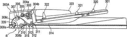
On the other hand, Fig. 2 is the amplification profile of the structure of explanation ADF300, among Fig. 2, and the 301st, original copy (loading) pallet of placement original copy bundle, the 303rd, the original copy that detects final original copy when detecting the original copy that loads loads detector.
The 1st tray sensor 320 and the 2nd tray sensor 321 are arranged on original copy (loading) pallet 301, detect the original copy length of sub scanning direction.The 323rd, be positioned at the side confinement plate on the loading pallet 301.In addition, on this side confinement plate 323, connect the not shown width detecting sensor in position that detects side confinement plate 323, can detect the original copy length of main scanning direction by this width detecting sensor.
And, can differentiate original size by these the 1st and the 2nd tray sensors 320,321 and width detecting sensor.In addition, the 322nd, the recovery end transducer is used to predict the most last original copy.
In addition, 304a is a separate roller, the 305th, and the separating pad of separated roller 304a crimping, 304b is a pick-up roller, when original copy is supplied with, if make paper feed roller shown in Figure 6 described later 350 counter-rotatings, then separate roller 304a to controlling party to rotation, and then, link with the rotation of this separate roller 304a, when pick-up roller 304b rotates to the paper supply direction, descend to position, transmit the paper of the superiors of original copy from the original copy shown in the top crimping with dashed lines from the retreating position shown in the solid line.
And the paper of the superiors of the original copy that is transmitted by pick-up roller 304b is transmitted by separate roller 304a.In addition, follow-up paper thus, prevents the overlapping transmission of original copy by being stopped by the restraint that is crimped on the separating pad 305 on the separate roller 304a.
The 306th, detect the block sensor of the original copy that transmits by separate roller 304a, the 307th, stop roller, in case touching, the original copy that is transmitted stops that roller 307 forms predetermined ring later on then stop, and carries out the diagonal correction thus.
And, after having carried out such diagonal correction, stop that by with predetermined timing paper feed roller 350 just being changeed, making roller 307 along the direction of transfer rotation, transmits original copy.In addition, the ring formation amount that is used for this diagonal correction can be adjusted, and adjusted value is stored in the nonvolatile memory, does not also lose even be constructed such that shutoff/connection of carrying out power supply thus.
In addition, just changeing by making this paper feed roller 350, pick-up roller 304b stops the rotation, and moves to retreating position from the position that is crimped on the original copy bundle.Here, though the rotation of separate roller 304a is stopped,, therefore transmit and do not produce obstacle for original copy because separate roller 304a can be carried out the rotation to direction of transfer by not shown unidirectional mechanism.
On the other hand, as the original copy paper supply unit, after for example the original copy that is sent by block sensor 307 has been detected by pickup 309 soon, as driving the original copy delivery unit by the motor 316 of reading shown in Figure 6 described later, for example transmit, read position R by being used for moving the original copy of reading original copy by reading roller 308a, 308b.
In addition, 308c moves when reading original copy, is used to make original copy to contact the platen roller of platen glass 102 closely.In addition, moving when reading original copy, as image fetching unit, for example scanning element 104 moves to position shown in Figure 1.
Here, after this pickup 309 has detected the top of original copy, original copy is further transmitted scheduled volume, arrive the timing that original copy reads position R, by serial i/F903 described later to the main body output picture elder generation signal time, after the end that has detected original copy, original copy is further transmitted scheduled volume, stop the output of picture elder generation signal then.
In addition, this original copy reads position R and can adjust according to from the change of the positional information of sensing element 100 time, by the value of having adjusted is stored in the nonvolatile memory, does not also lose even constitute shutoff/connection of carrying out power supply.
And then the original copy that has passed through to read the position carries out the row's paper or the upset of original copy by the 1st anti-roller 311 of row and the anti-roller 312 of the 2nd row.
Here, the anti-roller 311 of the 1st row drives by reading motor 316.In addition, the anti-roller 312 of the 2nd row is usually located at the position shown in the solid line that leaves the anti-roller 311 of the 1st row, can be moved to the position shown in the dotted line of the anti-roller 311 of crimping the 1st row by the anti-solenoid 324 of row shown in Figure 6 described later.
And, after the original copy end has passed through to read the position, the anti-roller 312 of the 2nd row is crimped onto on the anti-roller 311 of the 1st row by the anti-solenoid 324 of row, transmit original copy.In addition, the 310th, arrange the anti-pass sensor, can detect the top and the end of the original copy that sends.The 313rd, imprint cell is driven by marking solenoid shown in Figure 6 303 described later, can carry out the marking and handle on original copy.
In addition, the 315th, passage switches baffle plate, and this passage switches baffle plate 315 presses to downside by not shown spring.And, switch baffle plate 315 by depressing passage like this, can oppositely be sent to original copy from anti-roller 31 1 sides of the 1st row and stop roller 307 1 sides.In addition, rotate upward, can read anti-roller 311 1 sides of roller 308b one side direction the 1st row from the 2nd and carry out the original copy transmission by making passage switch baffle plate 315.
The 314th, discharge tray, be through with read in after, original copy is discharged also and is loaded on this discharge tray 314.In addition, can detect the open and-shut mode of the shell 300A of ADF, can open and close the open and-shut mode that transducer 335 detects ADF300 by ADF by cover sensor 333 shown in Figure 6 described later.
Fig. 3 is the profile that the structure of bar tape processing unit 400 is shown, in this example, this tape processing unit 400 is removed beyond the classification action of band classification, also have as the bookbinding of bookbinding action and the folder function of record-paper S doubling, by carrying out, can carry out saddle type bookbinding action bookbinding of record-paper S middle body and folding action.
Among Fig. 3, the 410th, acceptance is accepted the unit from the band of the band that printer unit 200 is discharged, the 403rd, the inlet transducer that carries out accepting the detection of the band unit 401 accepted by band, the band of being accepted is transmitted by the transfer roller 405 and the exit roller 407 of not shown transmission motor driven, is discharged on the intermediate tray 410.And the band of discharge turns back to shutter 412 by the blade 409 that is driven by not shown sliding-vane motor.
The 415th, detect the bundle of the band on the intermediate tray 410 and discharge transducer, discharge transducer 415 by bundle and discharge band, subsequently, make the adjustment action of the hanging of record-paper S by adjustment component 413a, 413b.Thus, the band that order is discharged is adjusted on intermediate tray 410, makes the band bundle.
And, generating band Shu Yihou, by stapling unit 600 bookbinding band bundles.Then, allow to up and down bundle roller 411 by driving and drop to dotted line state among the figure with the vane drive reverse rotation of above-mentioned sliding-vane motor, push the band bundle, the bundle roller 411 and the bundle that are reached driving by not shown row's altar are discharged the end that belt 417 is pushed the band bundle, and bundle is discharged on the pallet 421.
In addition, constituting bundle roller 411 with squeegee makes do not upset the bundle of having adjusted when the bundle roller transmits.In addition, row's altar reaches in order correctly to be configured control and uses stepper motor.
Fig. 4 illustrates the configuration structure of the operating display 500 of the upper surface that is arranged on sensing element 100.In addition, this operating display 500 has strong 502a, 502b, 502c, can carry out the LCD display unit 501 that this key shows.
Fig. 5 is the block diagram that the system global structure of image processing system 100A is shown, among Fig. 5,1 illustrates the control unit of output unit 100, the 2nd, the control unit of printer unit 200, the 3rd, the control unit of external device (ED) 250, the 900th, the control unit of ADF300, the 1000th, the control unit of trimmer 400, these unit carry out the access of data by bus or serial communication etc., obtain synchronously.
Here, the data that send to ADF300 from sensing element 100 are paper supply signals that urgency is loaded in the paper supply of the original copy the ADF300, row's paper signal of row's paper of the original copy that urging is through with reads in, and the row's of the confession paper matrix formula signal for row's paper state of decision original copy.In addition, the data that send to trimmer 400 from image processing system main body 100B are that image forms pattern (copy function, printing function etc.) signal, are housed in the mode signal in the trimmer 400, stripe size of being imported and signal regularly etc.
And, under the situation of moving, show that the data of the action of which kind of function of having used external device (ED) 250 are sent to ADF300, band after-treatment device 400 from sensing element 100, printer unit 200 respectively by communication.
The control unit 3 usefulness cables of said external device 250 are connected with the control unit 1 of sensing element 100, in this control unit 3, constitute the facsimile unit 4 of the transmitting-receiving of faxing, is various original copy information conversions that the signal of telecommunication is kept at the file unit 5 in the CD, the formatting unit 8 that expands into graphical information from generation of computers sign indicating number information, carry out the computer interface unit 7 with the interface of outer computer, be used for the graphics memory unit 9 of the information that sends from computer from the information stores of sensing element 100 or temporary transient storage and the core cell 10 of controlling above-mentioned various functions.
In addition, Fig. 6 is the block diagram of circuit structure that the control unit 900 of ADF300 is shown, among Fig. 6, and the 901st, CPU (central arithmetic processing apparatus).In CPU901, inside is installed with the ROM (read-only memory) that preserves with the corresponding control program of control flow shown in Figure 12 etc., and storage input data or operation are with the RAM (random access memory) of data.
In addition on the delivery outlet of CPU901, connecting above-mentioned paper supply motor 350, read various motors such as motor 316 or arrange anti-solenoid 324, various solenoids such as marking solenoid 303, on the input port of CPU901, connecting block sensor 306, row's anti-pass sensor 310, pickup 309, cover sensor 333 etc., CPU901 controls each unit according to the control program that is kept among the ROM.
In addition, the 903rd, the serial i/F (interface) with the control unit 1 of sensing element 100 carries out serial communication according to this serial i/F903, and carries out the transmitting-receiving of control data between the output unit 100.Here, the data that ADF300 receives from sensing element 100 are original copy control datas of putting down in writing control flow shown in Figure 12 etc., and the data that send to sensing element 100 from ADF300 are the paper supply end signal that finishes of the paper supply of expression original copy or above-mentioned picture elder generation signal.
Secondly, as the control unit of ADF300, the original copy the when image that control unit 900 for example is described reads transmits control action.At first, use Fig. 7 A~Fig. 7 E and Fig. 8 A~Fig. 8 D, the original copy transmission control action during the image that the single face original copy be described reads.
In this case, at first shown in Fig. 7 A, can confirm that by cover sensor 333 (with reference to Fig. 6) ADF shell 300A closes, and, can open and close transducer 335 by ADF and confirm that ADF300 close, in addition, transducer 303 is set under the situation of having placed original copy G on the original copy loading pallet 301 detecting by original copy, for sensing element 100, send " preparatory signal " that expression ADF300 can carry out control action.
Secondly, if receive " original copy paper supply signal " from the paper supply action beginning of the expression original copy G of the sensing element 100 that has received this " preparatory signal ", paper supply motor 350 (with reference to Fig. 6) is reversed.Thus, when separate roller 304A rotated to the paper supply direction, shown in Fig. 7 B, pick-up roller 304b limit moved to the position of crimping original copy bundle, the paper supply action of beginning original copy G to paper supply direction rotation limit from retreating position.
In addition, after paper feed roller action beginning,, then paper supply motor 350 is stopped at the transmission scheduled volume if block sensor 306 detects original copy G.Here, bigger by making such original copy detect later conveying capacity than " the original copy detection position of resistance shelves transducer 306~stop roller 307 positions ", form ring on the top of original copy, carry out diagonal and take out.
Then, make and read motor 316 (with reference to figure) and when just changeing, paper supply motor 350 is just being changeed, make to stop that roller 307 rotates to the paper supply direction.Thus, shown in Fig. 7 C, transmit the original copy that diagonal is taken out.In addition, be accompanied by the just commentaries on classics of this paper supply motor 350, pick-up roller 304b stops the rotation of paper supply direction, moves to position of readiness from the position of crimping original copy bundle.In addition, though separate roller 304b also stops the selection of paper supply direction, separate roller 304b is such as has been described, owing to possess unidirectional mechanism, is not therefore producing obstacle aspect the original copy transmission.
Here, be under the undersized situation at original copy G, when having detected the top of original copy G,, predict whether the current original copy G that is transmitting is final original copy, and be notified to sensing element 100 by recovery end transducer 322 with pickup 309.That is, under the situation of " original copy is arranged ", recovery end transducer 322 sends " non-final original copy prediction signal ", shown in Fig. 7 D, sends " final original copy prediction signal " to sensing element 100 in the absence of " original copy ".
On the other hand, after detecting original copy G with pickup 309 and having transmitted scheduled volume, read motor 316 and paper supply motor 350 stops by making, shown in Fig. 7 E, make plaintiff G temporarily stop at ready position as position of readiness, send original copy G to sensing element 100 and arrived ready position, be i.e. expression " the paper supply end signal " of paper supply that be through with.
Here, read in unit 100 after having received this " paper supply end signal ", read in action if can carry out by the image that scanning element 104 is implemented, then become the detecting unit action that to carry out the image reading state as detecting scanning element 104, as detection signal, send " the original copy supply signal " that read in beginning of indication original copy G for ADF300.
And, having received ADF300 as " the original copy paper supply signal " of this detection signal judges that scanning element 104 becomes and can carry out the state that image reads, make and read motor 316 and paper supply motor 350 is just changeing, begin the transmission of original copy G once more, be sent to original copy and read position R.
Promptly, when reading original image, usually read motor 316 and paper supply motor 350 stops by making, make original copy G temporarily stop at after the ready position, by receiving " original copy paper supply signal " from sensing element 100, begin the transmission of original copy G once more, original copy is sent to original copy reads position R.
In addition, the processing time of the original copy G that had for example before read sometimes finished in advance than the predetermined processing time.Its result as described later, received before original copy G arrives ready position " original copy paper supply signal " sometimes, in this case, made original copy G temporarily stop at ready position but be sent to original copy to read position R.
And, temporarily stop at ready position but be sent to original copy to read position R by making original copy G like this, can seek to improve the acceleration and deceleration action in the time of need not carrying out the original copy transmission when original copy is handled number of pages, can make the transmission action of original copy stable.
Then, shown in Fig. 7 E, read position R, then send and urge original copy to read " read start signal " of beginning for sensing element 100 if the top of original copy G arrives original copy.
Secondly, row's anti-pass sensor 310 detects original copy G, and then original copy end to be detected such as block sensor 306, if block sensor 306 has detected the original copy end, then by original copy transducer 303 is set and determines whether it is final original copy.That is, in the situation of " original copy is arranged ", original copy is provided with transducer 303 and sends " non-final original copy signal " for sensing element 100, shown in Fig. 8 A, in the absence of " original copy ", when block sensor 306 has detected the original copy end, send " final original copy signal ".
In addition, be judged as under the situation of non-final original copy, making 350 counter-rotatings of paper supply motor, beginning the paper supply action of next original copy, be judged as under the situation of final original copy, paper supply motor 350 is stopped.
Then, the end of original copy G to be detected such as pickup 309 detects at pickup 309 after the end of original copy G, original copy G is transmitted scheduled volume, shown in Fig. 8 B,, then send and urge original copy to read the original copy end signal of end if the terminal original copy that arrives of original copy reads position R.In addition, at this moment the row's of driving anti-solenoid 324 (with reference to Fig. 6) is crimped onto the anti-roller 312 of the 2nd row on the anti-roller 311 of the 1st row, and it is right to constitute the anti-roller of row, keeps conveying capacity.
Secondly, original copy ends to be detected such as row's anti-pass sensor 310, shown in Fig. 8 C, if original copy is terminal by row's anti-pass sensor 310, row's anti-pass sensor 310 detects the original copy end, then make and read motor 316 and stop, waiting for " original copy row paper signal " from row's paper action beginning of the indication original copy G of sensing element 100.And if receive " original copy row paper signal ", then motor 316 is read in starting once more, begins the transmission of original copy G once more.
Here, after detecting the original copy end with row's anti-pass sensor 310 like this,, shown in Fig. 8 D, can be loaded into original copy G in the discharge tray 314 reliably by transmitting " row anti-pass sensor G " disconnection " position~exit roller "+decision amount.In addition, after like this original copy G being loaded into discharge tray 314, making and read motor 316 and stop, stopping to arrange the driving of anti-solenoid 324, finish a series of action.
Secondly, use Fig. 9 A~9E, 10A~10E, the original copy during the image of 11A and 11B explanation two-sided original reads transmits control action.In addition, in this case, the end of original copy G to be detected such as pickup 309, detect at pickup 309 after the end of original copy G, original copy G is transmitted scheduled volume, such shown in Fig. 8 B as has been described, if the terminal original copy that arrives of original copy reads the position, then send the end signal that reads of urging " original copy reads end ",, therefore omit explanation owing to hereto carry out the control identical with the single face original copy.
At first, shown in Fig. 9 A, after the original copy end has arrived original copy and reads position R, if row's anti-pass sensor 310 detects the original copy end, then shown in Fig. 9 B, original copy G is transmitted scheduled volume, up to the position of original copy upset, then, make and read motor 316 and stop, original copy G is temporarily stopped.In addition, this original copy upturned position is that the original copy end has passed through the position that passage switches the switching position of baffle plate 315.
Secondly, temporary transient like this stopped reading motor 316 after, read motor 316 counter-rotatings by making, original copy G is oppositely transmitted.And the original copy G of so reverse transmission is sent to like that shown in Fig. 9 C by passage switching baffle plate 315 and stops roller 307 1 sides.And, if block sensor 306 detects the top of this original copy, then detect and begin to transmit scheduled volume and make later on and read motor 316 and stop from the top of original copy G.
In addition,, form ring, carry out diagonal and take out on the original copy top by making conveying capacity after this original copy G detects greater than " the original copy detection position of block sensor 306~stop roller 307 positions ".
Secondly, when paper supply motor 350 is just being changeed, make and read motor 316 counter-rotatings, transmit original copy G once more.And, subsequently original copy G has been transmitted scheduled volume after, the driving that stops to arrange anti-solenoid 324 shown in Fig. 9 D, is left the anti-roller 312 of the 2nd row from the anti-roller 311 of the 1st row.In addition, scheduled volume at this moment is as stopping that roller 307 clamps the top of original copy G, the distance that can transmit reliably.In addition, make simultaneously read motor 316 and stopped after, drive along positive veer.
Then, pickup 309 detects the top of original copy G, then, after original copy G transmitted scheduled volume, read motor 316 and paper supply motor 305 stops by making, make original copy G temporarily stop at ready position, to " the paper supply end signal " of the paper supply end of reading in unit 100 transmission expression original copy G.Read in unit 100 and received after " paper supply end signal ", read in action, " the original copy paper supply signal " that read in beginning of indication original copy G then takes place for ADF300 if can carry out image.
And the ADF300 that has received this " original copy paper supply signal " makes and reads motor 316 and paper supply motor 350 is just changeing, and begins the transmission of original copy G once more.Then, shown in Fig. 9 E, read position R, then send and urge image to read " read start signal " of beginning for sensing element 100 if the top of original copy G arrives original copy.
Secondly, row's anti-pass sensor 310 detects original copy G, and then original copy ends to be detected such as block sensor 306 if block sensor 306 has detected the original copy end, then are provided with transducer 303 by original copy and determine whether it is final original copy.That is, under the situation of " original copy is arranged ", original copy is provided with transducer 303 and sends " non-final original copy signal " for sensing element 100, shown in Figure 10 A, in the absence of " original copy ", when block sensor 306 has detected the original copy end, send " final original copy signal ".
In addition, be judged as under the situation of non-final original copy, making paper supply motor 350 counter-rotating, beginning the paper supply action of one page original copy down, paper supply motor 350 is being stopped being judged as.
Then, the end of original copy G to be detected such as pickup 309 detects the terminal of original copy G at pickup 309 and later original copy G is transmitted pre-scheduled volume, shown in Figure 10 B, if the terminal original copy that arrives of original copy reads position R, then send and urge image to read end " reading end signal ".
In addition, at this moment the row's of driving anti-solenoid 324 (with reference to Fig. 6) is crimped onto the anti-roller 312 of the 2nd row on the anti-roller 311 of the 1st row, and it is right to constitute the anti-roller of row, keeps conveying capacity.
Then, for be used for discharge tray on the original copy rotary movement that coincide of page or leaf order, original copy ends to be detected such as row's anti-pass sensor 310, shown in Figure 10 C, if original copy is terminal by row's anti-pass sensor 310, row's anti-pass sensor 310 detects this end, then makes to read motor 316 and stop, and original copy G is temporarily stopped.In addition, this original copy upturned position is that the original copy end has passed through the position that passage switches the switching position of baffle plate 315.
Then, make like this read motor 316 and temporarily stopped after, read motor 316 counter-rotatings by making, oppositely transmit original copy G.And the original copy G of so reverse transmission is sent to shown in Figure 10 D by channel path baffle plate 315 and stops roller 307 1 sides.
And if block sensor 306 detects the top of this original copy G, then after the top detection transmission scheduled volume of original copy G, the driving that stops to arrange anti-solenoid 324 shown in Figure 10 E, is left the anti-roller 312 of the 2nd row from the anti-roller 311 of the 1st row.In addition, scheduled volume at this moment is as stopping that roller 307 clamps the top of original copy G, the distance that can transmit reliably.In addition, make at the same time read motor 306 and stopped after, drive along positive veer.
Then, according to pickup 309, the top of the sequence detection original copy G of row's anti-pass sensor 310, and then, original copy ends to be detected such as block sensor 306.When block sensor 306 has detected the original copy end, under the situation of the final original copy of right and wrong, make 350 counter-rotatings of paper supply motor, begin the paper supply action of one page original copy G down, not shown paper supply motor 350 is stopped.
Then, the end of original copy G to be detected such as pickup 309 is if detected the end of original copy G by pickup 309, then anti-solenoid 324 is arranged in driving, shown in Figure 11 A, the anti-roller 312 of the 2nd row is crimped onto to constitute the anti-roller of row on the anti-roller 311 of the 1st row right, keep conveying capacity.
Then, original copy ends to be detected such as row's anti-pass sensor 310, shown in Figure 11 B, if original copy is terminal by row's anti-pass sensor 310, row's anti-pass sensor 310 detects the original copy end, then make and read motor 306 and stop, waiting for " original copy row paper signal " from row's paper action beginning of the indication original copy G of sensing element 100.And if received " original copy row paper signal ", then motor 316 is read in starting once more, begins the transmission of original copy G once more.
Here, by like this from detect the original copy ends by row's anti-pass sensor 310 after, transmit " row's anti-pass sensor " disconnection " position~arrange anti-roller "+scheduled volume, can be loaded into original copy G in the discharge tray 314 reliably.In addition, after being loaded into original copy G in the discharge tray 314 like this, reading motor 316 and stop, stopping to arrange the driving of anti-solenoid 324, finish a series of action by making.
Yet, such as has been described, when reading original image, usually read motor 316 and paper supply motor 350 stops by making, make original copy G temporarily stop at after the ready position, by receiving " original copy paper supply signal " from sensing element 100, begin the transmission of original copy G once more, be sent to original copy and read position R.
Here, should " original copy supply signal " be to arrive the what is called that reads original copy and move the signal of being exported when reading the position scanning element 104 being fixed on preposition.That is, arrive prepositions, can carry out not exporting before image reads up to scanning element 104.
But, scanning element 104 has been arrived after the preposition, do not need to wait for this original copy paper supply signal.Therefore, in this example, before original copy G arrives ready position, judge whether scanning element 104 has arrived the precalculated position, and whether received original copy paper supply signal, can carry out not stopping original copy under the situation that image reads being judged as, and directly transmit original copy.
Secondly, uses flow chart shown in Figure 12, the original copy transmission paper supply action specification during the image of consulting and using the single face original copy that Fig. 7 A~7E and Fig. 8 A~8D illustrated in addition reads illustrates this control as main points of the present invention.
At first, the CPU901 of the control unit 9500 of ADF300 is in step 2001, if the original copy paper supply signal of the paper supply action of ready position is arrived original copy G paper supply from the request of sensing element 100 in input, then in step 2002 as using Fig. 7 A~7E and Fig. 8 A~8D original copy in reading for the image of single face original copy to transmit control action illustrated, make 350 actions of paper supply motor, begin a series of original copy paper supply action.
Then, whether the original copy of judging paper supply in step 2003 arrives ready position, promptly, CPU901 is according to pickup 309 or be stored in the information of the memory etc. of CPU901 inside, detecting original copy G by pickup 309 when having transmitted scheduled volume later on, be judged as and arrived this position, at first, be not judged as and arrive not transmitting above-mentioned pre-timing.
When original copy has arrived ready position, in step 2010, temporarily make original copy G stop at ready position.Then, in step 2011, become and to carry out the status detection signal that image reads, if import original copy paper supply signal once more then step 2012, the original copy that begins to move transmits action from sensing element 100 as detecting scanning element 104.Transmit in the action at such original copy, sensing element 100 reads the action of original image.
On the other hand, before original copy arrives ready position, in step 2004, judge whether to have imported original copy paper supply signal once more.And, for example, if the processing of original copy G finished ahead of time than the predetermined processing time, then before original copy G arrives ready position, become and to carry out the status detection signal that image reads as detecting scanning element 104, if imported original copy paper supply signal from sensing element 100, then then CPU901 is same as described above in step 2005 judges whether original copy has arrived ready position.
And, when original copy has arrived ready position, original copy G is not stopped, and in step 2006, as it is illustrated like that to use Fig. 7 A~7E and Fig. 8 A~8D original copy in reading for the image of single face original copy to transmit control action, proceeds that original copy G is sent to original copy and reads the later a series of original copy transmission of position R and move.In such original copy conveyer belt action, sensing element 100 reads the action of original image.
Then, wait for that in step 2007 above-mentioned a series of original copy transmits the end of action, promptly, such shown in Fig. 8 D that had narrated, CPU901 judges according to the original copy end point detection signal that is undertaken by row's anti-pass sensor 301 and from the information such as original copy row paper signal of sensing element 100 whether the original copy transmission finishes after a series of action, transmit at original copy under the situation about finishing, original copy G load be sent in the discharge tray 314 after, stop original copy and transmit action and finish.
Like this, before original copy G arrives ready position, be judged as and carry out image when reading, transmit by not stopping original copy, when can seek to improve original copy and handle number of pages,, therefore can make the transmission action of original copy stable owing to do not carry out the acceleration and deceleration action of original copy when transmitting.
In addition, in example of the present invention, as the front is narrated, as control unit, for example, the CPU901 basis of the control unit 900 of ADF300 and corresponding various control programs such as flow process shown in Figure 12 are controlled each several parts, and also can adopt the directly actuated structure of control unit of image processing system main unit.
As described above, if according to an example of the present invention, then before arriving ready position, original copy detects under the situation that to carry out the state that image reads, read position R by making original copy not stop at ready position to original copy and transmit original copy, can when seeking to improve original copy processing number of pages, make the transmission action of original copy stable.
In addition, before arriving ready position, original copy do not detect under the situation that to carry out the state that image reads, make original copy stop at ready position, before arriving ready position, original copy detected under the situation that to carry out the state that image reads, read position R by making original copy not stop at ready position to original copy and transmit original copy, can when seeking to improve original copy processing number of pages, make the transmission action of original copy stable.
Claims (5)
1. original copy feedway, this original copy feedway is sent to the predetermined position of reading that can be undertaken that image reads by the image fetching unit with Manuscript exposure unit to original copy, it is characterized in that: have
Original copy is sent to the above-mentioned original copy delivery unit that reads position of readiness that reads the upstream of position;
Detect above-mentioned image fetching unit and be in the status detection unit that can read image;
Above-mentioned original copy delivery unit is controlled, so that original copy arrive above-mentioned read position of readiness before, not detecting by above-mentioned detecting unit under the situation that above-mentioned image fetching unit is in the above-mentioned state that can read image, make original copy stop at the above-mentioned position of readiness that reads; Original copy arrive above-mentioned read position of readiness before, detecting by above-mentioned detecting unit under the situation that above-mentioned image fetching unit is in the above-mentioned state that can read image, original copy is not stopped at above-mentionedly to be read position of readiness and original copy is sent to the above-mentioned control unit that reads the position
Above-mentioned control unit makes above-mentioned original copy delivery unit transmit original copy in the mode through the top of the mobile above-mentioned Manuscript exposure unit that reads the position that is fixed in above-mentioned below of reading the position when being read the image that is sent to the above-mentioned original copy that reads the position by above-mentioned image fetching unit.
2. original copy feedway according to claim 1 is characterized in that:
The above-mentioned state that can read image is meant that above-mentioned Manuscript exposure unit has arrived the above-mentioned state of position that reads that moves.
3. original copy feedway according to claim 1 is characterized in that:
Above-mentioned detecting unit has arrived the above-mentioned signal of exporting when reading the position that moves by detecting in above-mentioned Manuscript exposure unit, be in the state that can read image thereby detect above-mentioned image fetching unit.
4. original copy feedway according to claim 1 is characterized in that:
Above-mentioned control unit is controlled above-mentioned original copy delivery unit, so that make original copy stop at above-mentioned read position of readiness after, detect above-mentioned image fetching unit and be under the situation of the above-mentioned state that can read image, once more original copy is sent to the above-mentioned position of reading.
5. image processing system is characterized in that: have the described original copy feedway of claim 1, and have the image formation unit that forms image according to the image of the original copy that has been read by above-mentioned image fetching unit on thin slice.
Applications Claiming Priority (2)
| Application Number | Priority Date | Filing Date | Title |
|---|---|---|---|
| JP2002139128A JP3986884B2 (en) | 2002-05-14 | 2002-05-14 | Document feeder and image forming apparatus having the same |
| JP139128/2002 | 2002-05-14 |
Publications (2)
| Publication Number | Publication Date |
|---|---|
| CN1461137A CN1461137A (en) | 2003-12-10 |
| CN1204734C true CN1204734C (en) | 2005-06-01 |
Family
ID=29416898
Family Applications (1)
| Application Number | Title | Priority Date | Filing Date |
|---|---|---|---|
| CNB031307396A Expired - Fee Related CN1204734C (en) | 2002-05-14 | 2003-05-13 | Manuscript supply device and imaging forming device |
Country Status (3)
| Country | Link |
|---|---|
| US (2) | US7557968B2 (en) |
| JP (1) | JP3986884B2 (en) |
| CN (1) | CN1204734C (en) |
Families Citing this family (15)
| Publication number | Priority date | Publication date | Assignee | Title |
|---|---|---|---|---|
| JP3986884B2 (en) * | 2002-05-14 | 2007-10-03 | キヤノンファインテック株式会社 | Document feeder and image forming apparatus having the same |
| KR100560719B1 (en) * | 2004-07-14 | 2006-03-13 | 삼성전자주식회사 | Automatic document feeder with anti-skew function |
| JP4603935B2 (en) * | 2005-05-31 | 2010-12-22 | キヤノン株式会社 | Image reading device |
| JP4325628B2 (en) * | 2005-10-17 | 2009-09-02 | ブラザー工業株式会社 | Document feeder |
| JP4910752B2 (en) * | 2007-02-19 | 2012-04-04 | セイコーエプソン株式会社 | Media processing device |
| DE602008002867D1 (en) * | 2007-08-09 | 2010-11-18 | Oki Data Kk | An image reading apparatus, an image forming apparatus, an image reading apparatus with an image reading apparatus and an image forming apparatus |
| JP4816964B2 (en) * | 2007-11-30 | 2011-11-16 | ブラザー工業株式会社 | Document feeder |
| JP4669025B2 (en) * | 2008-06-06 | 2011-04-13 | シャープ株式会社 | Image processing apparatus and image processing method |
| US8199383B2 (en) | 2008-07-17 | 2012-06-12 | Kabushiki Kaisha Toshiba | Auto document feeding device and image scanning device |
| US20120091651A1 (en) * | 2010-10-14 | 2012-04-19 | Toshiba Tec Kabushiki Kaisha | Auto-document feeder and document feeding method |
| JP5278413B2 (en) * | 2010-11-30 | 2013-09-04 | ブラザー工業株式会社 | Image reading apparatus and program used therefor |
| JP5825549B2 (en) * | 2011-06-08 | 2015-12-02 | 株式会社リコー | Sheet conveying apparatus, image reading apparatus, and image forming apparatus |
| JP6341443B2 (en) * | 2014-02-25 | 2018-06-13 | 株式会社リコー | Sheet placing apparatus, image forming apparatus, and image reading apparatus |
| JP7225764B2 (en) * | 2018-12-17 | 2023-02-21 | コニカミノルタ株式会社 | Imaging system, image forming device, imaging device and program |
| JP7300926B2 (en) * | 2019-08-07 | 2023-06-30 | シャープ株式会社 | IMAGE READING DEVICE AND IMAGE FORMING APPARATUS WITH IMAGE READING DEVICE |
Family Cites Families (28)
| Publication number | Priority date | Publication date | Assignee | Title |
|---|---|---|---|---|
| US4391505A (en) * | 1981-10-19 | 1983-07-05 | Xerox Corporation | Over-platen document registration apparatus |
| JPS59174858A (en) * | 1983-03-24 | 1984-10-03 | Minolta Camera Co Ltd | Control mechanism of copying machine |
| GB2214321B (en) * | 1988-01-22 | 1991-07-10 | Ricoh Kk | Copier with an automatic document feeder |
| JP2746954B2 (en) * | 1988-11-12 | 1998-05-06 | 株式会社リコー | Copier |
| US5118089A (en) * | 1989-09-05 | 1992-06-02 | Konica Corporation | Automatic document feeding apparatus |
| JP2700826B2 (en) * | 1989-09-14 | 1998-01-21 | コニカ株式会社 | Automatic document feeder |
| US5223905A (en) | 1990-02-22 | 1993-06-29 | Konica Corporation | Automatic document conveying device |
| US5204724A (en) * | 1990-08-16 | 1993-04-20 | Sharp Kabushiki Kaisha | Document feeding apparatus and a document feeding method with upstream pressure release |
| US5203554A (en) * | 1990-09-07 | 1993-04-20 | Sharp Kabushiki Kaisha | Plurality document feeding apparatus and method for copying machines |
| US5351112A (en) * | 1992-01-13 | 1994-09-27 | Canon Kabushiki Kaisha | Original feeding apparatus and image forming system with it |
| JPH05286606A (en) * | 1992-04-10 | 1993-11-02 | Konica Corp | Copying machine with automatic document feeding device |
| US5423526A (en) * | 1992-06-26 | 1995-06-13 | Canon Kabushiki Kaisha | Sheet supplying apparatus |
| JPH07245696A (en) * | 1994-03-04 | 1995-09-19 | Minolta Co Ltd | Image forming device |
| JP2865001B2 (en) * | 1994-12-20 | 1999-03-08 | 村田機械株式会社 | Image processing device |
| JP3002860B2 (en) * | 1995-12-28 | 2000-01-24 | ニスカ株式会社 | Automatic document feeder |
| JPH1051599A (en) | 1996-07-31 | 1998-02-20 | Ricoh Co Ltd | Image processor |
| JP3749332B2 (en) * | 1997-02-18 | 2006-02-22 | コニカミノルタビジネステクノロジーズ株式会社 | Image reading device |
| US6145834A (en) * | 1997-06-12 | 2000-11-14 | Konica Corporation | Automatic document feeder having a document shunting path |
| JPH11249348A (en) * | 1998-02-27 | 1999-09-17 | Minolta Co Ltd | Image forming device |
| JP2000224393A (en) * | 1999-01-29 | 2000-08-11 | Konica Corp | Image reader and copying device |
| JP3744728B2 (en) * | 1999-06-15 | 2006-02-15 | 富士ゼロックス株式会社 | Sheet conveying apparatus and image forming apparatus using the same |
| JP3882439B2 (en) * | 2000-01-06 | 2007-02-14 | コニカミノルタホールディングス株式会社 | Image forming apparatus |
| JP4395951B2 (en) * | 2000-01-13 | 2010-01-13 | コニカミノルタホールディングス株式会社 | Image reading apparatus and image forming apparatus using the same |
| JP3885442B2 (en) * | 2000-01-17 | 2007-02-21 | 富士ゼロックス株式会社 | Image forming apparatus |
| US7212321B2 (en) * | 2000-06-13 | 2007-05-01 | Nisca Corporation | Simple and compact automatic document feed device containing a single adjusting unit |
| JP4365995B2 (en) | 2000-06-30 | 2009-11-18 | キヤノン株式会社 | Image forming apparatus, image forming apparatus control method, and storage medium |
| JP3888056B2 (en) * | 2000-12-26 | 2007-02-28 | コニカミノルタホールディングス株式会社 | Image forming apparatus and discharged sheet stacking apparatus |
| JP3986884B2 (en) * | 2002-05-14 | 2007-10-03 | キヤノンファインテック株式会社 | Document feeder and image forming apparatus having the same |
-
2002
- 2002-05-14 JP JP2002139128A patent/JP3986884B2/en not_active Expired - Fee Related
-
2003
- 2003-05-06 US US10/429,787 patent/US7557968B2/en not_active Expired - Fee Related
- 2003-05-13 CN CNB031307396A patent/CN1204734C/en not_active Expired - Fee Related
-
2009
- 2009-06-04 US US12/478,095 patent/US7957042B2/en not_active Expired - Fee Related
Also Published As
| Publication number | Publication date |
|---|---|
| US7957042B2 (en) | 2011-06-07 |
| US20030214096A1 (en) | 2003-11-20 |
| CN1461137A (en) | 2003-12-10 |
| JP3986884B2 (en) | 2007-10-03 |
| US20090238620A1 (en) | 2009-09-24 |
| JP2003333274A (en) | 2003-11-21 |
| US7557968B2 (en) | 2009-07-07 |
Similar Documents
| Publication | Publication Date | Title |
|---|---|---|
| CN1204734C (en) | Manuscript supply device and imaging forming device | |
| CN1061935C (en) | Sheet binding apparatus capable of performing two kinds of binding processes | |
| JP4615334B2 (en) | Sheet post-processing apparatus and image forming apparatus having the same | |
| CN1264073C (en) | Paper post-treating device with dislocation placing mechanism | |
| CN1734358A (en) | Sheet finisher and control method thereof | |
| CN1275451C (en) | Image reading apparatus and image forming apparatus | |
| CN1855987A (en) | Image forming apparatus and image formation controlling method | |
| CN1258447C (en) | Paper treatment device and image forming apparatus | |
| JPH10194565A (en) | Finisher | |
| CN1380588A (en) | Imaging device | |
| CN1526622A (en) | Pape sheets piling apparatus | |
| CN1161669C (en) | Image forming apparatus and image forming method | |
| JP3609995B2 (en) | Image forming apparatus and image forming method | |
| CN1526626A (en) | Sheets handling apparatus and image forming apparatus | |
| JP4512625B2 (en) | Image forming apparatus, image forming system including the same, program, and recording medium | |
| CN1764226A (en) | Document reader and image forming apparatus | |
| CN1673897A (en) | Sheet processing apparatus having a sheet insertion function, control method therefor, image forming apparatus | |
| CN1147759C (en) | Image formation device | |
| JP3132381B2 (en) | Document reading apparatus and document reading method | |
| CN1526621A (en) | Paper sheets handling apparatus and paper sheets handling method | |
| US7864370B2 (en) | Copy machine with image rotation and back surface reading based on memory capacity required | |
| JP3793270B2 (en) | Facsimile machine | |
| US6553193B1 (en) | Image forming apparatus and image forming method with punching mode | |
| JP3782500B2 (en) | Image forming apparatus, image forming method, and image forming system | |
| US20030214685A1 (en) | Image forming apparatus and image forming method |
Legal Events
| Date | Code | Title | Description |
|---|---|---|---|
| C06 | Publication | ||
| PB01 | Publication | ||
| C10 | Entry into substantive examination | ||
| SE01 | Entry into force of request for substantive examination | ||
| C14 | Grant of patent or utility model | ||
| GR01 | Patent grant | ||
| CF01 | Termination of patent right due to non-payment of annual fee | ||
| CF01 | Termination of patent right due to non-payment of annual fee |
Granted publication date: 20050601 Termination date: 20200513 |