CN1198679A - Photocatalytic air disinfection - Google Patents
Photocatalytic air disinfection Download PDFInfo
- Publication number
- CN1198679A CN1198679A CN96197457A CN96197457A CN1198679A CN 1198679 A CN1198679 A CN 1198679A CN 96197457 A CN96197457 A CN 96197457A CN 96197457 A CN96197457 A CN 96197457A CN 1198679 A CN1198679 A CN 1198679A
- Authority
- CN
- China
- Prior art keywords
- air
- equipment
- photocatalyst
- coated
- filter medium
- Prior art date
- Legal status (The legal status is an assumption and is not a legal conclusion. Google has not performed a legal analysis and makes no representation as to the accuracy of the status listed.)
- Pending
Links
Images






Classifications
-
- A—HUMAN NECESSITIES
- A61—MEDICAL OR VETERINARY SCIENCE; HYGIENE
- A61L—METHODS OR APPARATUS FOR STERILISING MATERIALS OR OBJECTS IN GENERAL; DISINFECTION, STERILISATION OR DEODORISATION OF AIR; CHEMICAL ASPECTS OF BANDAGES, DRESSINGS, ABSORBENT PADS OR SURGICAL ARTICLES; MATERIALS FOR BANDAGES, DRESSINGS, ABSORBENT PADS OR SURGICAL ARTICLES
- A61L9/00—Disinfection, sterilisation or deodorisation of air
- A61L9/16—Disinfection, sterilisation or deodorisation of air using physical phenomena
- A61L9/18—Radiation
- A61L9/20—Ultraviolet radiation
- A61L9/205—Ultraviolet radiation using a photocatalyst or photosensitiser
-
- A—HUMAN NECESSITIES
- A61—MEDICAL OR VETERINARY SCIENCE; HYGIENE
- A61L—METHODS OR APPARATUS FOR STERILISING MATERIALS OR OBJECTS IN GENERAL; DISINFECTION, STERILISATION OR DEODORISATION OF AIR; CHEMICAL ASPECTS OF BANDAGES, DRESSINGS, ABSORBENT PADS OR SURGICAL ARTICLES; MATERIALS FOR BANDAGES, DRESSINGS, ABSORBENT PADS OR SURGICAL ARTICLES
- A61L9/00—Disinfection, sterilisation or deodorisation of air
- A61L9/015—Disinfection, sterilisation or deodorisation of air using gaseous or vaporous substances, e.g. ozone
- A61L9/04—Disinfection, sterilisation or deodorisation of air using gaseous or vaporous substances, e.g. ozone using substances evaporated in the air without heating
- A61L9/12—Apparatus, e.g. holders, therefor
- A61L9/122—Apparatus, e.g. holders, therefor comprising a fan
-
- A—HUMAN NECESSITIES
- A61—MEDICAL OR VETERINARY SCIENCE; HYGIENE
- A61L—METHODS OR APPARATUS FOR STERILISING MATERIALS OR OBJECTS IN GENERAL; DISINFECTION, STERILISATION OR DEODORISATION OF AIR; CHEMICAL ASPECTS OF BANDAGES, DRESSINGS, ABSORBENT PADS OR SURGICAL ARTICLES; MATERIALS FOR BANDAGES, DRESSINGS, ABSORBENT PADS OR SURGICAL ARTICLES
- A61L9/00—Disinfection, sterilisation or deodorisation of air
- A61L9/16—Disinfection, sterilisation or deodorisation of air using physical phenomena
- A61L9/18—Radiation
- A61L9/20—Ultraviolet radiation
-
- F—MECHANICAL ENGINEERING; LIGHTING; HEATING; WEAPONS; BLASTING
- F24—HEATING; RANGES; VENTILATING
- F24F—AIR-CONDITIONING; AIR-HUMIDIFICATION; VENTILATION; USE OF AIR CURRENTS FOR SCREENING
- F24F3/00—Air-conditioning systems in which conditioned primary air is supplied from one or more central stations to distributing units in the rooms or spaces where it may receive secondary treatment; Apparatus specially designed for such systems
- F24F3/12—Air-conditioning systems in which conditioned primary air is supplied from one or more central stations to distributing units in the rooms or spaces where it may receive secondary treatment; Apparatus specially designed for such systems characterised by the treatment of the air otherwise than by heating and cooling
-
- F—MECHANICAL ENGINEERING; LIGHTING; HEATING; WEAPONS; BLASTING
- F24—HEATING; RANGES; VENTILATING
- F24F—AIR-CONDITIONING; AIR-HUMIDIFICATION; VENTILATION; USE OF AIR CURRENTS FOR SCREENING
- F24F7/00—Ventilation
- F24F7/04—Ventilation with ducting systems, e.g. by double walls; with natural circulation
-
- A—HUMAN NECESSITIES
- A61—MEDICAL OR VETERINARY SCIENCE; HYGIENE
- A61L—METHODS OR APPARATUS FOR STERILISING MATERIALS OR OBJECTS IN GENERAL; DISINFECTION, STERILISATION OR DEODORISATION OF AIR; CHEMICAL ASPECTS OF BANDAGES, DRESSINGS, ABSORBENT PADS OR SURGICAL ARTICLES; MATERIALS FOR BANDAGES, DRESSINGS, ABSORBENT PADS OR SURGICAL ARTICLES
- A61L2209/00—Aspects relating to disinfection, sterilisation or deodorisation of air
- A61L2209/10—Apparatus features
- A61L2209/14—Filtering means
-
- F—MECHANICAL ENGINEERING; LIGHTING; HEATING; WEAPONS; BLASTING
- F24—HEATING; RANGES; VENTILATING
- F24F—AIR-CONDITIONING; AIR-HUMIDIFICATION; VENTILATION; USE OF AIR CURRENTS FOR SCREENING
- F24F8/00—Treatment, e.g. purification, of air supplied to human living or working spaces otherwise than by heating, cooling, humidifying or drying
- F24F8/20—Treatment, e.g. purification, of air supplied to human living or working spaces otherwise than by heating, cooling, humidifying or drying by sterilisation
- F24F8/22—Treatment, e.g. purification, of air supplied to human living or working spaces otherwise than by heating, cooling, humidifying or drying by sterilisation using UV light
-
- Y—GENERAL TAGGING OF NEW TECHNOLOGICAL DEVELOPMENTS; GENERAL TAGGING OF CROSS-SECTIONAL TECHNOLOGIES SPANNING OVER SEVERAL SECTIONS OF THE IPC; TECHNICAL SUBJECTS COVERED BY FORMER USPC CROSS-REFERENCE ART COLLECTIONS [XRACs] AND DIGESTS
- Y02—TECHNOLOGIES OR APPLICATIONS FOR MITIGATION OR ADAPTATION AGAINST CLIMATE CHANGE
- Y02A—TECHNOLOGIES FOR ADAPTATION TO CLIMATE CHANGE
- Y02A50/00—TECHNOLOGIES FOR ADAPTATION TO CLIMATE CHANGE in human health protection, e.g. against extreme weather
- Y02A50/20—Air quality improvement or preservation, e.g. vehicle emission control or emission reduction by using catalytic converters
Landscapes
- Health & Medical Sciences (AREA)
- Engineering & Computer Science (AREA)
- Chemical & Material Sciences (AREA)
- General Health & Medical Sciences (AREA)
- Veterinary Medicine (AREA)
- Public Health (AREA)
- Epidemiology (AREA)
- Life Sciences & Earth Sciences (AREA)
- Animal Behavior & Ethology (AREA)
- General Engineering & Computer Science (AREA)
- Mechanical Engineering (AREA)
- Combustion & Propulsion (AREA)
- Chemical Kinetics & Catalysis (AREA)
- Disinfection, Sterilisation Or Deodorisation Of Air (AREA)
- Catalysts (AREA)
- Central Air Conditioning (AREA)
- Exhaust Gas Treatment By Means Of Catalyst (AREA)
Abstract
Description
与相关申请的交互参照Cross-references to related applications
本申请是D.Yogi Goswami于1995年9月6日向美国专利和商标局申请的、名称为“用于提高空气质量的光催化系统”的美国专利申请No.08/524,284的部分继续申请,母申请中公开的内容在此处引作参考。技术领域This application is a continuation-in-part of U.S. Patent Application No. 08/524,284, filed September 6, 1995, in the U.S. Patent and Trademark Office by D. Yogi Goswami, entitled "Photocatalytic System for Improving Air Quality," parent The content disclosed in the application is incorporated herein by reference. technical field
本发明涉及通过光催化氧化对空气进行消毒的方法,具体地说,涉及这样的方法:提供相对湿度在约40%以上的需消毒的空气,然后在紫外光(UV)的存在下使空气与光催化剂接触,这样,空气中的至少一部分微生物由于光催化氧化而被杀灭。本发明还涉及空气消毒设备,这些设备具有被UV光照射的涂布有光催化剂的表面,并具有使空气与涂布有光催化剂的表面接触的装置以及将空气的相对湿度保持在约40%以上的装置,这样,当用UV光照射涂布有光催化剂的表面时,空气中的微生物由于光催化氧化而被杀灭。The present invention relates to a method for disinfecting air by photocatalytic oxidation, in particular to a method for providing air to be disinfected with a relative humidity above about 40% and then decontaminating the air in the presence of ultraviolet light (UV) The photocatalyst is contacted so that at least a portion of microorganisms in the air are killed due to photocatalytic oxidation. The present invention also relates to air disinfection devices having a photocatalyst-coated surface irradiated with UV light and having means for bringing air into contact with the photocatalyst-coated surface and maintaining the relative humidity of the air at about 40% The above device, in this way, when the surface coated with the photocatalyst is irradiated with UV light, microorganisms in the air are killed due to photocatalytic oxidation.
美国人的时间90%是在室内度过的,在室内时,他们暴露于各种承载在空气中的污染物,例如挥发性的有机化合物(VOC)、氡和生物。在80年代的一项研究中,环境保护署(EPA)得出结论,室内空气污染比室外空气污染对健康形成更大的危险。室内空气污染被认为会引起医疗费用的显著增加和劳动生产率下降。Americans spend 90 percent of their time indoors, where they are exposed to various airborne pollutants such as volatile organic compounds (VOCs), radon, and organisms. In a study in the 1980s, the Environmental Protection Agency (EPA) concluded that indoor air pollution posed a greater health risk than outdoor air pollution. Indoor air pollution is believed to cause significant increases in medical costs and decreased labor productivity.
在建筑物循环系统中,来自独立源的污染物水平其自身可能并不具有显著危险。然而,许多建筑物存在一个以上会引起室内空气污染的源头。由这样的室内空气污染物引起的疾病有时称作“污染建筑物综合征”。引起室内空气污染的原因是不受欢迎的颗粒物质、不受欢迎的化学物质和微生物污染物。在前两种情形,常用的技术时常通过过滤或通风来加以解决。挥发性有机化合物(VOC)和微生物污染的问题则产生更严重的障碍。In building circulation systems, levels of pollutants from independent sources may not in themselves present a significant hazard. However, many buildings have more than one source of indoor air pollution. Illnesses caused by such indoor air pollutants are sometimes referred to as "polluted building syndrome". Indoor air pollution is caused by unwanted particulate matter, unwanted chemicals and microbial pollutants. In the first two cases, the usual techniques are often solved by filtration or ventilation. Problems of volatile organic compounds (VOCs) and microbial contamination present even more serious obstacles.
由于有这么多的美国人在具有机械加热、冷却和通风系统的办公室和建筑物中度过大量的时间,这样的系统形成生物污染危险。近年来,室内环境的生物问题已受到相当关注。费城1976年爆发的军团病(Legionnaires′disease)可能是由室内污染物引起的疾病中最受公众关注的案例。With so many Americans spending a significant amount of time in offices and buildings with mechanical heating, cooling and ventilation systems, such systems pose a biocontamination hazard. Biological issues in indoor environments have received considerable attention in recent years. The 1976 outbreak of Legionnaires' disease in Philadelphia is perhaps the most publicized case of an illness caused by indoor pollutants.
生物污染物包括细菌、霉菌和病毒。受污染的中央空气系统可成为生物污染物的滋生地,强迫通风可将污染物在整个建筑物中扩散。Biological contaminants include bacteria, mold and viruses. A polluted central air system can be a breeding ground for biological pollutants, and forced air can spread the pollutants throughout a building.
在过去的三十至四十年中,建筑物的结构和作用已发生了显著变化。建筑物外壳已变得更紧密,由此,在加热、通风和空调(HVAC)系统中较少使用室外空气。微生物不那么容易通过与新鲜空气的混合而稀释。节约能量程序已导致建筑物的室内环境更湿润,从而有利于某些类型的微生物生长。The structure and function of buildings have changed significantly over the past thirty to forty years. Building envelopes have become tighter, whereby less outside air is used in heating, ventilation, and air conditioning (HVAC) systems. Microorganisms are not so easily diluted by mixing with fresh air. Energy conservation programs have resulted in more humid indoor environments in buildings, which favors the growth of certain types of microorganisms.
由于在一些建筑物中维修程序被忽视,成为微生物滋养物的过量污垢在HVAC系统的壁龛中累积。这导致称作建筑物相关疾病、建筑物疾病和污染建筑物综合征的疾病。背景技术Because maintenance procedures are neglected in some buildings, excess fouling that becomes a microbial nutrient builds up in the alcoves of the HVAC system. This leads to diseases known as building-related disease, building disease, and polluted building syndrome. Background technique
已有几种微生物颗粒控制技术(包括机械滤器和静电滤器)可用来作为建筑物强制通风加热/冷却系统的一部分来减少可吸入颗粒的室内浓度。微生物滤器由于其成本低、操作容易而已被用于空气和其他气体的消毒。可将这些滤器构建成不仅可除去微生物而且还可除去亚微米细粒。为经济而有效地使用这些滤器,待过滤的空气中气溶胶含量必须低。(分散在空气中的微生物、颗粒和液滴称作气溶胶)。这些滤器的缺点是他们不能永久地除去污染物,只能将污染物移至另一个介质(即滤器)中。阻塞将引起管道中有高的压降。Several microbial particle control technologies, including mechanical and electrostatic filters, are available to reduce indoor concentrations of respirable particles as part of a building's forced-air heating/cooling system. Microbial filters have been used for disinfection of air and other gases due to their low cost and ease of operation. These filters can be constructed to remove not only microorganisms but also submicron fines. In order to use these filters economically and effectively, the air to be filtered must be low in aerosol content. (Microorganisms, particles and droplets dispersed in the air are called aerosols). The disadvantage of these filters is that they do not permanently remove the contaminants, they only move the contaminants to another medium (ie the filter). A clog will cause a high pressure drop in the pipe.
一个可行的方法是永久地除去污染物并产生无毒性的残渣。紫外消毒已在过去被广泛地用来杀灭生物污染物和使毒性化学物质降解。One possible approach is to permanently remove the contaminants and produce a non-toxic residue. UV disinfection has been used extensively in the past to kill biological contaminants and degrade toxic chemicals.
这样的紫外处理在消毒方面效果很好,但室内环境还可能被低水平的毒性化学物质(如甲醛、苯乙烯和甲苯等)污染。单独的UV光能已证明不能有效地降解这些化学物质。例如,Raupp和Dibble的美国专利No.5,045,288以及Robertson和Henderson的美国专利No.4,892,712、4,966,759和5,032,241使用了紫外来处理含污染物的流体和气体。Such UV treatments work well in terms of disinfection, but indoor environments can also be contaminated with low levels of toxic chemicals such as formaldehyde, styrene, and toluene. UV light energy alone has proven ineffective in degrading these chemicals. For example, US Patent No. 5,045,288 to Raupp and Dibble and US Patent Nos. 4,892,712, 4,966,759 and 5,032,241 to Robertson and Henderson use ultraviolet light to treat fluids and gases containing contaminants.
已得到广泛关注的另一个可选择的方法是光催化氧化,它包括用光催化剂(例如TiO2)来完全降解水中的烃类物质和杀灭微生物。Patel在Antibacterial EffectOf Catalyzed Radiation,Masters Thesis,University of Florida,Gainesville(1993)中报道说,TiO2粉末在水中照射60-120分钟之后,可杀灭粘质沙雷氏菌(Serratia marcescens)。Saito等,J. Photochem.Photobiol.B:Biol.,14,369-79(1992);Matsunaga,J.Antibact.Antifungic Agents,13,211-20(1980);Nagane等,J.Dent.Res.,68,1696-7(1989)和Moriaka等,Caries.Res.,22,230-1(1988)报道说,TiO2在水中曝气60-120分钟之后,可杀灭大肠杆菌(E.coli)和嗜酸乳杆菌(Lactobacillus acidophilus)。Wang等,Proceedingsof the First International Conference on TiO2 Photocatalytic Purification andTreatment of Water and Air(London,Ontario,Canada,November,8-13,1992)pp.733-9;Wang等,Proc.AWWA Conf.(San Antonio,TX,1993);Savat等,J.Catalysis,127,167-77(1991)和Anderson等,Further Catalytic Purificatino ofWater and Air,1,405-20(1993)报道了三氯乙烯(TCE)和其他有机污染物的气相去毒。但仍需要一种从空气中除去微生物的方法。发明概述Another alternative that has received much attention is photocatalytic oxidation, which involves the use of photocatalysts (such as TiO2 ) to completely degrade hydrocarbons in water and kill microorganisms. Patel reported in Antibacterial Effect Of Catalyzed Radiation, Masters Thesis, University of Florida, Gainesville (1993), that TiO2 powder can kill Serratia marcescens after irradiating in water for 60-120 minutes. Saito et al., J. Photochem. Photobiol. B: Biol., 14, 369-79 (1992); Matsunaga, J. Antibact. Antifungic Agents, 13, 211-20 (1980); Nagane et al., J. Dent. Res. , 68, 1696-7 (1989) and Moriaka et al., Caries.Res., 22, 230-1 (1988) report that TiO 2 can kill Escherichia coli (E.coli ) and Lactobacillus acidophilus. Wang et al., Proceedings of the First International Conference on TiO2 Photocatalytic Purification and Treatment of Water and Air (London, Ontario, Canada, November, 8-13, 1992) pp.733-9; Wang et al., Proc.AWWA Conf. (San Antonio, TX, 1993); Savat et al., J.Catalysis, 127, 167-77 (1991) and Anderson et al., Further Catalytic Purificatino of Water and Air, 1, 405-20 (1993) reported trichlorethylene (TCE) and other organic Vapor phase detoxification of pollutants. But there is still a need for a way to remove microbes from the air. Summary of the invention
本发明满足上述需要。The present invention fulfills the above needs.
现已发现,通过在控制的湿度条件下UV光对光催化剂的作用而激发的光催化氧化可对含微生物的空气消毒。It has now been found that photocatalytic oxidation stimulated by the action of UV light on photocatalysts under controlled humidity conditions can disinfect air containing microorganisms.
本发明的主要目的是提供一种可行的室内空气净化和去毒方法,它可用于新的或已安装的空气管道系统。The main object of the present invention is to provide a feasible indoor air purification and detoxification method which can be used in new or installed air duct systems.
本发明的另一个目的是提供一种较廉价的去毒反应器,它可置于有问题的建筑物的管道系统内。该反应器单元可配置在空气分配系统的一个或几个主管道内,或反应器可配置在通向室内调风器的每个管道中。Another object of the present invention is to provide a less expensive detoxification reactor which can be placed in the plumbing system of a problematic building. The reactor unit can be placed in one or several main ducts of the air distribution system, or the reactor can be placed in each duct leading to the room register.
本发明的又一目的是提供一种去毒反应器单元,它可容易地配置在新的循环系统中,或作为对有问题的循环系统的改进,或作为独立的空气过滤单元,或作为出口通风系统,或者它可用作真空清洗系统的出口室。Yet another object of the present invention is to provide a detoxification reactor unit that can be easily configured in a new circulation system, or as a retrofit to a problematic circulation system, or as a stand-alone air filtration unit, or as an outlet ventilation system, or it can be used as an outlet chamber for a vacuum cleaning system.
本发明的还有一个目的是提供一种装置,用该装置可对通过反应器的空气流率和该气流的湿度进行调节,以使作用于催化剂(例如TiO2)的UV光能产生最大的杀菌效率。Yet another object of the present invention is to provide a device with which the air flow rate through the reactor and the humidity of this air flow can be adjusted to maximize the UV light energy acting on the catalyst (e.g. TiO2 ). Bactericidal efficiency.
本发明的另一个重要目的是提供一种光催化氧化系统,它不仅能杀灭微生物,而且能消除有机化学物质和室内空气中常常会闻到的、由微生物和挥发性有机污染物产生的异味。Another important object of the present invention is to provide a photocatalytic oxidation system that can not only kill microorganisms but also eliminate organic chemicals and odors produced by microorganisms and volatile organic pollutants that are often smelled in indoor air .
本发明的另一个目的是提供一种涂布有催化剂的管道,它在合适波长的光入射在涂布有催化剂的管道表面上的情况下将不被微生物污染。Another object of the present invention is to provide a catalyst-coated pipe which will not be contaminated by microorganisms when light of a suitable wavelength is incident on the surface of the catalyst-coated pipe.
本发明的又一个目的是提供净化由密封室内排出的被污染空气的单机实施方式,在该密封室内,进行某些有毒的操作,例如油漆密封室。Yet another object of the present invention is to provide a stand-alone embodiment for purifying polluted air exhausted from a hermetic chamber where certain toxic operations are performed, such as a paint hermetic chamber.
具体地说,该单机实施方式还可用于医院,包括对空气的无菌状态的要求非常严格的手术室、医生等候室、休息室和其他可进行封闭循环且需要减少异味和高度净化以给使用这些设施的人提供舒适环境的地方。Specifically, the stand-alone embodiment can also be used in hospitals, including operating rooms, doctor's waiting rooms, lounges, and other areas that require a closed cycle and require odor reduction and high purification for use in hospitals that have very strict requirements on the sterile state of the air. These facilities are places where people provide a comfortable environment.
因此,根据本发明的一个实施方式,对含微生物的空气流进行消毒的方法包括下述步骤:提供相对湿度在约40%以上、含微生物的空气流;使上述气流与具有预定带隙能量的光催化剂在具有相应于光催化剂带隙能量的波长的光子源的存在下接触,这样,通过光催化氧化将气流中的至少一部分微生物杀灭。本发明的较佳方法还控制气流的流速,这样,气流中的至少一部分微生物被杀灭。Accordingly, according to one embodiment of the present invention, a method of disinfecting an air stream containing microorganisms comprises the steps of: providing an air stream containing microorganisms at a relative humidity above about 40%; The photocatalyst is contacted in the presence of a source of photons having a wavelength corresponding to the energy of the photocatalyst's bandgap, such that at least a portion of the microorganisms in the gas stream are killed by photocatalytic oxidation. The preferred method of the present invention also controls the flow rate of the gas stream so that at least a portion of the microorganisms in the gas stream are killed.
本发明还包括实施本发明方法的设备。因此,根据本发明的另一实施方式,对一定数量含微生物的空气进行消毒的设备具有以下部分:涂布有光催化剂的表面,所述光催化剂具有预定的带隙能量;用具有相应于光催化剂带隙能量的波长的光子源照射涂布有光催化剂的表面的装置;使所述空气与涂布有光催化剂的表面接触的装置以及将空气的相对湿度维持在约40%以上的装置,这样,当用UV光照射涂布有光催化剂的表面时,上述空气与光催化剂接触后空气中的至少一部分微生物即由于光催化氧化而被杀灭。The invention also includes apparatus for carrying out the method of the invention. Therefore, according to another embodiment of the present invention, an apparatus for disinfecting a quantity of air containing microorganisms has the following parts: a surface coated with a photocatalyst having a predetermined band gap energy; means for irradiating the surface coated with the photocatalyst with a source of photons at a wavelength of the bandgap energy of the catalyst; means for contacting said air with the surface coated with the photocatalyst and means for maintaining the relative humidity of the air above about 40%, In this way, when the surface coated with the photocatalyst is irradiated with UV light, at least a part of microorganisms in the air are killed due to photocatalytic oxidation after the above-mentioned air comes into contact with the photocatalyst.
本发明的方法和设备适合于在建筑物的HVAC系统内使用或作为独立的单元。因此,根据本发明该实施方式的一个方面,用于对含微生物的空气进行消毒的设备含以下部分:管道,空气通过那里进行移动;送风机,它与管道连接,使空气通过管道移动;光催化剂,它位于管道中,具有预定的带隙能量;灯,它位于与光催化剂足够近的地方,用具有相应于光催化剂带隙能量的波长的光子源对光催化剂进行照射;湿度控制器,调节至将管道中的空气相对湿度保持在约40%以上,这样,当用灯发出的UV光照射光催化剂时,上述空气与光催化剂接触后空气中的至少一部分微生物即由于光催化氧化而被杀灭。The method and apparatus of the present invention are suitable for use within a building's HVAC system or as a stand-alone unit. Therefore, according to an aspect of this embodiment of the present invention, the apparatus for sterilizing air containing microorganisms comprises the following parts: a duct through which the air moves; a blower connected to the duct to move the air through the duct; a photocatalyst , which is located in the pipe and has a predetermined bandgap energy; a lamp, which is located close enough to the photocatalyst to irradiate the photocatalyst with a photon source having a wavelength corresponding to the photocatalyst bandgap energy; a humidity controller, which regulates To keep the relative humidity of the air in the pipeline at more than about 40%, so that when the photocatalyst is irradiated with the UV light emitted by the lamp, at least a part of the microorganisms in the air are killed due to photocatalytic oxidation after the above-mentioned air contacts the photocatalyst .
根据本发明该实施方式的另一部分,对含微生物的空气进行消毒的独立的设备具有以下部分:容器,空气通过那里移动;送风机,它与容器连接,使空气通过容器移动;位于容器中的光催化剂,它具有预定的带隙能量;灯,它用具有相应于光催化剂带隙能量的波长的光子源来照射光催化剂;湿度控制器,调节至将容器中的空气相对湿度保持在约40%以上,这样,当用UV光照射光催化剂时,上述空气与光催化剂接触后空气中的至少一部分微生物即由于光催化氧化而被杀灭。According to another aspect of this embodiment of the invention, the stand-alone apparatus for sterilizing air containing microorganisms has the following parts: a container through which the air moves; a blower connected to the container to move the air through the container; a catalyst, which has a predetermined bandgap energy; a lamp, which irradiates the photocatalyst with a photon source having a wavelength corresponding to the photocatalyst's bandgap energy; and a humidity controller, adjusted to maintain the relative humidity of the air in the container at about 40% As above, in this way, when the photocatalyst is irradiated with UV light, at least a part of microorganisms in the air will be killed due to photocatalytic oxidation after the above-mentioned air contacts the photocatalyst.
本发明还包括以下发现:用具有预定的带隙能量的光催化剂涂布过滤介质,可延长能捕捉含微生物的生物气溶胶的过滤介质的有效寿命。当在相对湿度可有效引发上述光催化氧化的条件下用具有相应于光催化剂带隙能量的波长的光子源照射过滤介质时,至少一部分被过滤介质捕捉的微生物被杀灭,由此对捕捉了生物气溶胶的过滤介质进行了净化,这样,过滤介质可继续捕捉生物气溶胶,延长了滤器更换的时间间隔。The present invention also includes the discovery that coating a filter medium with a photocatalyst having a predetermined bandgap energy prolongs the effective life of a filter medium capable of capturing bioaerosols containing microorganisms. When the filter medium is irradiated with a photon source having a wavelength corresponding to the energy of the photocatalyst's bandgap under conditions of relative humidity effective to induce the above-mentioned photocatalytic oxidation, at least a portion of the microorganisms trapped by the filter medium are killed, thereby affecting the captured The filter media for bioaerosols is decontaminated so that the filter media continues to capture bioaerosols, extending the time between filter changes.
根据本发明的该实施方式,可捕捉生物气溶胶的过滤介质具有与含微生物的气流接触的上游表面(upstream surface),而该表面涂布有光催化剂。过滤介质最好含于HEPA滤器或微孔滤器内。According to this embodiment of the invention, the bioaerosol-capturing filter medium has an upstream surface in contact with the microbe-containing airflow, and the surface is coated with a photocatalyst. The filter media is preferably contained within a HEPA filter or microporous filter.
通过下面结合附图对优选实施方式的说明,可清楚地看到本发明的上述的和其他的目的、特征和优点。附图的简单说明The above and other objects, features and advantages of the present invention can be clearly seen through the following description of preferred embodiments in conjunction with the accompanying drawings. A brief description of the drawings
图1是用于建筑物的、装有本发明反应器系统的典型的加热/冷却管道系统的示意图;Figure 1 is a schematic diagram of a typical heating/cooling piping system for a building incorporating the reactor system of the present invention;
图2是用于说明其他视图的横截面的反应器单元的示意透视图;Fig. 2 is a schematic perspective view of a reactor unit illustrating a cross-section of other views;
图3是说明反应器单元的几个主要部件的分解示意图;Figure 3 is an exploded schematic diagram illustrating several major components of the reactor unit;
图4、5和6是沿图2中4-4线的的反应器单元的各种实施方式的纵向横截面,显示UV灯相对于有涂层部件的排列;Figures 4, 5 and 6 are longitudinal cross-sections of various embodiments of the reactor unit along line 4-4 in Figure 2, showing the arrangement of the UV lamps relative to the coated parts;
图7是单机实施方式的纵向横截面;Figure 7 is a longitudinal cross-section of a stand-alone embodiment;
图8是图7的独立单元的立式变型;Figure 8 is a vertical variant of the stand-alone unit of Figure 7;
图9是沿9-9线的横截面,显示位于管道周界的UV灯;Figure 9 is a cross-section along line 9-9 showing the UV lamps located at the perimeter of the pipe;
图10是说明UV灯相对于催化性插入物的位置的示意透视图;Figure 10 is a schematic perspective view illustrating the position of the UV lamp relative to the catalytic insert;
图11是本发明的另一单机实施方式的纵向横截面视图;Figure 11 is a longitudinal cross-sectional view of another stand-alone embodiment of the present invention;
图12是本发明的又一单机实施方式的纵向横截面视图;Figure 12 is a longitudinal cross-sectional view of yet another stand-alone embodiment of the present invention;
图13是本发明的催化性插入物的纵向横截面视图;Figure 13 is a longitudinal cross-sectional view of a catalytic insert of the present invention;
图14是本发明的反应器单元的另一实施方式的示意透视图;Figure 14 is a schematic perspective view of another embodiment of the reactor unit of the present invention;
图15是本发明的催化性插入物的示意透视图;Figure 15 is a schematic perspective view of a catalytic insert of the present invention;
图16是本发明的UV灯装置的示意透视图;Figure 16 is a schematic perspective view of the UV lamp device of the present invention;
图17是本发明的催化性插入物的另一实施方式的示意透视图;Figure 17 is a schematic perspective view of another embodiment of the catalytic insert of the present invention;
图18是固定在壁上的UV灯的纵向横截面视图;Figure 18 is a longitudinal cross-sectional view of a UV lamp fixed on a wall;
图19是使用图18中所示的固定在壁上的UV灯的反应器单元的示意透视图;Figure 19 is a schematic perspective view of a reactor unit using the wall-fixed UV lamp shown in Figure 18;
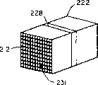
图20和21是本发明的反应器单元的又一实施方式的示意透视图;Figures 20 and 21 are schematic perspective views of yet another embodiment of the reactor unit of the present invention;
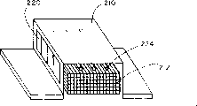
图22和23是固定在HVAC系统的空气供应调节器中的本发明的反应器实施方式的示意透视图;22 and 23 are schematic perspective views of a reactor embodiment of the present invention secured in an air supply regulator of an HVAC system;
图24描述在30% RH的条件下通过光解和光催化氧化杀灭粘质沙雷氏菌的情况;Figure 24 describes the situation of killing Serratia marcescens by photolysis and photocatalytic oxidation under the condition of 30%RH;
图25描述在50% RH的条件下通过光分解和光催化氧化杀灭粘质沙雷氏菌的情况;Figure 25 describes the situation of killing Serratia marcescens by photolysis and photocatalytic oxidation under the condition of 50%RH;
图26描述在85% RH的条件下通过光分解和光催化氧化杀灭粘质沙雷氏菌的情况;Figure 26 describes the situation of killing Serratia marcescens by photolysis and photocatalytic oxidation under the condition of 85%RH;
图27描述不同湿度对杀灭粘质沙雷氏菌的影响;Figure 27 describes the impact of different humidity on killing Serratia marcescens;
图28描述在RH为50%、 UV强度为100W/m2的条件下用两种不同的反应器结构通过光分解和光催化氧化杀灭粘质沙雷氏菌的情况;Figure 28 depicts the situation of killing Serratia marcescens by photolysis and photocatalytic oxidation with two different reactor structures under the condition that RH is 50%, UV intensity is 100W/m 2 ;
图29描述在不同的UV强度的条件下杀灭粘质沙雷氏菌的情况。Figure 29 depicts the killing of Serratia marcescens under conditions of different UV intensities.
值得注意的是,附图并不一定按比例绘制,而是将某些要素扩大以更清楚地显示本发明的各个方面和它们的优点。本发明的最佳实施方式It should be noted that the drawings are not necessarily to scale, rather some elements may be exaggerated to more clearly show aspects of the invention and their advantages. BEST MODE FOR CARRYING OUT THE INVENTION
下面参见附图,各附图中相同的部件用相同的数字表示,图1是实施本发明方法的本发明的一个装置,其中数字10表示本发明的系统。在大多数建筑物中,送风机/风扇将空气从进行空气调节的空间的各个区域通过进风口和颗粒/气溶胶滤器12抽入管道系统中。然后,空气可在加热炉的加热盘管或空调机的加热/冷却盘管/空气调节单元14的热泵之上通过。冷却盘管由于其在冷却空气的同时将湿气冷凝而起着除湿机的作用。Referring to the accompanying drawings below, identical parts are represented by identical numerals in each accompanying drawing, and Fig. 1 is a device of the present invention implementing the inventive method, wherein numeral 10 represents the system of the present invention. In most buildings, blowers/fans draw air from various areas of the air-conditioned space through air intakes and particle/aerosol filters 12 into the ductwork. The air can then pass over the heating coils of a furnace or the heating/cooling coils of an air conditioner/heat pump of the air conditioning unit 14 . The cooling coil acts as a dehumidifier because it condenses moisture while cooling the air.
空气调节单元14的风扇65将强制空气在盘管13和15之上通过,进入管道系统18。在图1中,沿管道18有一个主反应器21。在许多装置中,有它即足够。然而,在图1的实施方式中,在管道系统18的支线中还有一系列反应器单元22。The fan 65 of the air conditioning unit 14 forces air to pass over the coils 13 and 15 and into the ductwork 18 . In FIG. 1 there is a main reactor 21 along line 18 . In many installations, it is sufficient. However, in the embodiment of FIG. 1 there is also a series of
图2概略地说明了反应器21中的主要部件。这些部件还将出现在反应器22中。这些主要部件是涂布有催化剂的衬套29、一排UV灯24和表面28涂布有催化剂的网格。在有些情况下,仅使用涂布过的衬套或涂布过的网格。这里使用两者。在本发明中,涂布有催化剂的衬套和网格统称作催化性插入物。灯最好发射UV-A谱段的低能光子和UV-B谱段的较低能量部分。UV波长最好在约300-400nm之间。FIG. 2 schematically illustrates the main components in the reactor 21 . These components will also be present in
在图4、5和6中可见到反应器22的各种内部配置。在每个反应器中有通过电线25和26与电源连接的一排UV灯24。电线25和26显示在图5和6中,但相似的电线将出现在所有实施方式中。在这些实施方式中灯24发出的紫外线射在有涂层的衬套29(图4)或网格的一个侧面和有涂层的衬套(图6)上,网格和衬套之一或二者可用光催化剂涂布。紫外线还可射向有涂层的网格28的两侧和在网格两侧的有涂层的衬套区段29和29′。参见图5。Various internal configurations of
基本上任何在相对湿度大于约40%的空气存在下用光子源照射时可催化光催化氧化反应的物质都适合在本发明中用作光催化剂。本领域的技术人员可容易地确定这些物质而无需过多的实验。合适的光催化剂的例子有半导体材料(例如ZnO2、TiO2)等。然而,基本上可使用任何半导体材料或将半导体材料与贵金属或其他金属(例如银)结合使用。较好的是,光催化剂与具有相应于该光催化剂的带隙能量的波长的光子源结合使用。优选的光子源是UV光。优选的光催化剂是TiO2,其带隙能量在波长300-400nm的UV光子的能量范围之内。Essentially any material that can catalyze a photocatalytic oxidation reaction when irradiated with a photon source in the presence of air at a relative humidity of greater than about 40% is suitable for use as a photocatalyst in the present invention. Those skilled in the art can readily determine these without undue experimentation. Examples of suitable photocatalysts are semiconductor materials (eg ZnO 2 , TiO 2 ) and the like. However, essentially any semiconductor material can be used or combined with a noble metal or other metal such as silver. Preferably, the photocatalyst is used in combination with a photon source having a wavelength corresponding to the photocatalyst's bandgap energy. A preferred source of photons is UV light. A preferred photocatalyst is TiO2 with a bandgap energy in the energy range of UV photons of wavelength 300-400nm.
网格28可由任何材料制成,只要能用常用方法将光催化剂粘附在其上面即可。管道衬套29可由任何材料制成,只要能用常用方法将光催化剂沉积和粘附在其内表面31上即可。The
用于网格的这些纤维和材料的一些例子包括天然纤维(例如棉或羊毛)、人造纤维和合成纤维(例如人造丝、聚酯、聚丙烯、和特氟隆)以及其它纤维(例如阻燃纤维材料以及碳和所有其它功能性纤维材料)。网格28的构造为稀松的机织结构、非织造结构或针织结构,或它们的组合,这样,它令空气可相对自由地流动而没有过大的压力下降。Some examples of these fibers and materials for mesh include natural fibers such as cotton or wool, man-made and synthetic fibers such as rayon, polyester, polypropylene, and Teflon, and other fibers such as flame retardant fiber materials as well as carbon and all other functional fiber materials). The
在通过反应器22和离开支导管30、32、34和36之后,空气被导向室内调风器中。显然,在大的建筑物中,可能有几十个从许多主要管道分枝的30-36型导管。各房间通常有一个空气返回口。空气从各房间返回并通过一系列由数字37、38、39和40表示的管道在系统中循环。这些管道含滤器12,并合并于集气管42中,集气管42将空气送回空气调节单元14的进口侧,在空气调节单元14,空气可能被重新冷却或重新加热,然后送回管道系统18。After passing through
反应器21中循环的空气在涂布有催化剂的网格28或涂布过的管道衬套29之上的保持时间很重要。管道系统内空气的流速用检测器44测量。The residence time of the air circulating in the reactor 21 above the catalyst coated
在图1中,常用的流速检测器44(Mamac Anubar型流速检测器)位于主要的管道系统18中。流速检测器时常置于各反应器22内,它是就下述独立单元所描述的那种类型的反应器。In FIG. 1 , a conventional flow detector 44 (Mamac Anubar type flow detector) is located in the main piping system 18 . A flow rate detector is often placed within each
空气流速越快,则空气将在网格28的催化表面之上保持的时间或与衬套29的涂布过的表面31的接触时间越少。当流速或体积排送量降低时,保持时间增加。如前面所述,通常最好在所有时间保持空气在整个建筑物中流通。这里,对空气速度进行调节,通过控制在催化表面上的保持时间,以最大程度地消灭有害物质。The faster the air velocity, the less time the air will remain above the catalytic surface of the
该保持时间将随空气流速、管道大小、催化表面面积和其他物理特性而变化。不管怎样,空气速度即体积流速从检测器44输入微处理器62。微处理器62反过来控制风扇马达64的速度,从而控制风扇65的排气量。送风机的速度始终调节到产生所需的停留时间。例如,在进行的实验中,在2英寸厚的催化性网格上,约70英尺/分的空气速度可产生良好的消毒和杀灭率。This hold time will vary with air flow rate, tube size, catalytic surface area, and other physical characteristics. Regardless, air velocity, or volumetric flow rate, is input from detector 44 to microprocessor 62 . The microprocessor 62 in turn controls the speed of the fan motor 64 , thereby controlling the exhaust volume of the fan 65 . The speed of the blower is always adjusted to produce the desired residence time. For example, in experiments performed, an air velocity of about 70 ft/min on a 2 inch thick catalytic grid produced good disinfection and kill rates.
图14是具有正方形空气通道的蜂窝型结构的催化性插入物。图15是具有圆形或椭圆形通道的催化性插入物。可用其他几何形状替换图14和15中显示的结构。催化性插入物内涂布有催化剂的表面积可如图17所示,通过加入涂布有催化剂的翼片而增加。也可使用褶状表面。催化性插入物可以由塑料、纤维、金属和其他材料制成。网格或衬套的表面积将取决于污染物的预期浓度,可根据所涉及的装置凭经验加以确定而无需过多的实验。Figure 14 is a catalytic insert of honeycomb structure with square air channels. Figure 15 is a catalytic insert with circular or oval channels. Other geometries may be substituted for the structures shown in Figures 14 and 15. The catalyst-coated surface area within the catalytic insert can be increased by adding catalyst-coated fins as shown in FIG. 17 . Pleated surfaces may also be used. Catalytic inserts can be made of plastic, fiber, metal and other materials. The surface area of the mesh or liner will depend on the expected concentration of contaminants and can be determined empirically for the installation involved without undue experimentation.
循环空气的相对湿度也很重要。空气的相对湿度水平对杀灭微生物是决定性的,其水平必须能在用UV光照射光催化剂时,微生物与光催化剂接触后有效地使至少一部分微生物由于光催化氧化而被杀灭,即相对湿度应在约40%以上。相对湿度较好地在约40-70%之间,更好地在约50-60%之间,最好约为50%。The relative humidity of the circulating air is also important. The relative humidity level of the air is decisive for killing microorganisms, and its level must be able to effectively kill at least a part of the microorganisms due to photocatalytic oxidation after the microorganisms are in contact with the photocatalyst when the photocatalyst is irradiated with UV light, that is, the relative humidity should be Above about 40%. The relative humidity is preferably between about 40-70%, more preferably between about 50-60%, most preferably about 50%.
参见图1,沿管道18的长度配置的是增湿器/去湿器单元50(Sun Chemical公司生产的SUN 13型),它由Mamac公司生产的HV-2222型检测器探头控制。若检测器52检测到空气的相对湿度小于50%,则启动喷水或喷雾单元54,令其以细雾的形式向气流中喷入足够的湿气,将相对湿度提高至约50%。若相对湿度超过70%,则用此处用冷却盘管56表示的去湿器系统除去湿气。盘管56可以是单独的单元,但在许多情况,可利用单元14的盘管。也可设置单独的备用盘管58。可用图1所示的冷却盘管或其他惯用技术(例如干燥剂除湿)将水凝聚,由此实现空气去湿。Referring to Fig. 1, disposed along the length of conduit 18 is a humidifier/dehumidifier unit 50 (SUN 13, manufactured by Sun Chemical), which is controlled by a detector probe, Model HV-2222, manufactured by Mamac. If the detector 52 detects that the relative humidity of the air is less than 50%, the water spray or spray unit 54 is activated to spray enough moisture into the airflow in the form of fine mist to increase the relative humidity to about 50%. If the relative humidity exceeds 70%, the moisture is removed by a dehumidifier system, shown here as cooling coil 56. Coil 56 may be a separate unit, but in many cases, the coil of unit 14 may be utilized. A separate backup coil 58 may also be provided. Air dehumidification can be achieved by condensing the water using cooling coils as shown in Figure 1 or other conventional techniques such as desiccant dehumidification.
选择相对湿度和流速的要求是,应能完全杀灭空气中的微生物。在我们的实验中,当相对湿度为50%、空气在循环风道的2英寸厚的催化性网格之上通过的速度约为70英尺/分时,可完全杀灭空气中的微生物。在本发明中,杀灭的微生物的定义为:被完全杀死的微生物,不包括仅被打昏、休克或其他的不能活动但能复活的微生物。The requirement for selecting relative humidity and flow rate is that it should be able to completely kill the microorganisms in the air. In our experiments, when the relative humidity is 50%, the air velocity over the 2-inch thick catalytic mesh of the recirculation duct is about 70 feet per minute, and the airborne microorganisms can be completely killed. In the present invention, the definition of killed microorganisms is: microorganisms that are completely killed, excluding microorganisms that are only stunned, shocked or otherwise inactive but can be revived.
图1揭示了主反应器21和分支反应器22。在较小的装置中,将仅使用反应器21。在较大的装置中,将仅使用反应器22。他们合并在图1中以显示也可使用它们的组合。FIG. 1 discloses a main reactor 21 and a
反应器可自身具有独立的相对湿度和流速控制装置,这样,每个反应器作为独立的光催化设备进行运作。或者,可使各反应器适应于它安装在其内的HVAC系统的相对湿度和流速控制,由此将HVAC系统转换成本发明的装置。在这样的情况下,反应器将基本上由催化性插入物和用于照射其表面的UV光源组成。这些设备的光催化剂涂层表面积,最好调节至在HVAC系统的相对湿度和空气流速的条件下,能提供与循环空气的足够接触以将空气中所含的至少一部分微生物杀灭。The reactors can have their own independent relative humidity and flow rate controls, so that each reactor operates as an independent photocatalytic device. Alternatively, each reactor can be adapted to the relative humidity and flow rate control of the HVAC system in which it is installed, thereby converting the HVAC system to the apparatus of the present invention. In such a case, the reactor will essentially consist of a catalytic insert and a UV light source for illuminating its surface. The photocatalyst coating surface area of these devices is preferably adjusted to provide sufficient contact with the circulating air to kill at least a portion of the microorganisms contained therein under the conditions of relative humidity and air flow rate of the HVAC system.
图4、5和6揭示了在单个反应器22内的灯和催化剂位置的各种实施方式。图中只示意地表示了UV灯24。可用任何常用的方式支承灯,使UV射线照射在它们的各自的催化表面上。4 , 5 and 6 disclose various embodiments of lamp and catalyst locations within a
图4是矩形衬套催化性插入物29位于管道区段之内的反应器22。其内表面涂布有数字31表示的TiO2。Figure 4 is a
图5是具有以下结构的反应器22:催化性插入物为衬套29和29′,它们在管道之内;在它们之间有一排(或几排)UV灯24位于滤器/网格28的相反侧。UV灯24横放在管道内。Figure 5 is a
若合适,反应器22的滤器/网格28可以是能捕捉生物气溶胶的过滤介质。最好在所有系统中使用这样的过滤介质,它将令空气充分流动而没有过大的压力下降。能捕捉生物气溶胶的滤器包括HEPA滤器、静电滤器和微孔滤器。通过用光催化剂涂布迎着气流的过滤介质表面,在相对湿度能有效产生光催化氧化的条件下用UV光照射光催化剂将杀灭被滤器捕捉的生物气溶胶中至少一部分微生物。这样,使过滤介质捕捉的气溶胶得以净化,从而延长滤器的有效寿命。If appropriate, the filter/
图6是具有以下结构的反应器22:一系列细长的UV灯24横放在管道内,与过滤介质催化性插入物28相邻。FIG. 6 is a
图9是反应器的横截面,它显示了在催化性插入物的衬套29之内,沿管道周界配置并与滤器28相邻的UV灯24。Figure 9 is a cross-section of the reactor showing the
本发明还提供这样一种方法,在该方法中,通过用光催化剂涂料涂布管道内壁,使管道区段产生涂布有光催化剂的表面。然后将UV灯安装在管道中以照射涂布有光催化剂的管道内壁。The present invention also provides a method in which a section of pipe is produced with a photocatalyst-coated surface by coating the inner wall of the pipe with a photocatalyst coating. A UV lamp was then installed in the pipe to irradiate the inner wall of the pipe coated with the photocatalyst.
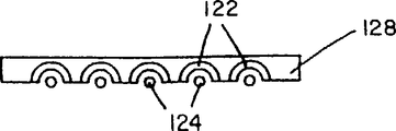
用于照射催化性插入物的UV灯装置可以固定在管道壁上。图18是固定在壁上的灯装置128,镀铝的反射镜122将灯124发出的UV光反射。图19说明固定在壁上的装置120与涂布有光催化剂的插入物126之间的关系。A UV lamp unit for irradiating the catalytic insert can be fixed on the pipe wall. FIG. 18 is a
反应器还可安装在HVAC系统的空气供应调节器中。图22和23显示了适合这样的安装的单元的细部。当空气从HVAC系统中流出时,它不直接进入房间,而首先使其流过调节器210,用本发明的光催化消毒方法进行处理。该单元基本上由催化性插入物212、UV光源224和空气出口220组成。可使用单个或多个出口,这取决于所需的停留时间。催化性插入物的内表面涂布有光催化剂。UV灯由电池或电源(未标出)运行。The reactor can also be installed in the air supply regulator of the HVAC system. Figures 22 and 23 show details of a unit suitable for such an installation. As air exits the HVAC system, it does not enter the room directly, but is first passed through the
调节器的UV灯224和催化性插入物212是可移动式的。图4-6的反应器中任何催化性插入物均适合与调节器210一起使用。The regulator's
可在管道系统之外独立地采用本发明的要点。这样的独立单元80见图7。该单元80包括具有进口84和出口86的壳体82。处于进口和出口之间的是容器88,它包括控制风扇90、增湿器92、去湿器93、用于驱动风扇48的风扇马达64和催化性插入物96,从一系列UV灯98发出的UV光即照射在催化性插入物96上。空气速度检测器99确定气流排送量。在壳体82上面有第二容器100,它是用来封闭微处理器102的。用于单元80的电源经电线104和106通过控制处理器102供给至系统。若通过单元80外面的空气调节系统能确保适当的湿度,单元80可无需其自己的湿度控制系统进行运转。或者,独立单元可与增湿器或去湿器串联起来进行运转而不偏离本发明的方法或设备。若在单元80的设计和建造中采用与壳体82的截面面积相配的恒定空气流速风扇48,以提供所需的空气在催化剂上面流过的停留时间,独立单元80还可在无空气速度检测器99的情况下进行运转。The gist of the invention can be employed independently of the piping system. Such an
独立单元80可由轮108支承,这样,它可在室内容易地移向最适合促进气流在整个房间中循环的位置。此外,可将独立单元用作房间的排气单元,在该单元中有人们希望经处理后再排向大气的有害烟气。例如,在油漆车间或其他工厂中,可将独立单元80安装在屋顶或任何外墙上,或可以与室内空调器相同的方式将其改装成窗支承式的。不管怎样,在将受污染的空气排入大气之前先将其净化。The self-contained
独立单元的控制和操作与前面描述的相同。当接通电源后,风扇48便将空气抽入进口84。颗粒预滤器是用来保持独立单元的内部不受污垢污染的,因为污垢会损害有涂层的网格96或有涂层的衬套(若衬套与网格组合使用的话)。颗粒预滤器可以是HEPA型的、静电型的或其他市场上有售的装置。与安装在HVAC系统的管道中的装置不同,颗粒预滤器可以与独立单元一起使用,因为在这些独立单元中,与预滤器相关的压力下降是可以接受的。或者,若空气中颗粒很少,也可省去预滤器。在风扇开始旋转时即同时照射UV光98。Control and operation of the stand-alone unit is the same as previously described. The fan 48 draws air into the inlet 84 when the power is turned on. The particulate pre-filter is used to keep the interior of the self-contained unit free from dirt that would damage the coated mesh 96 or the coated liner if used in combination with the liner. Particulate prefilters can be HEPA type, electrostatic type or other commercially available devices. Unlike units installed in the ductwork of an HVAC system, particulate prefilters can be used with stand-alone units where the pressure drop associated with the prefilter is acceptable. Alternatively, the pre-filter can be omitted if the air contains very few particles. UV light 98 is irradiated simultaneously when the fan starts to rotate.
检测器44将测量空气速度,所得信息输入至微处理器102。然后微处理器将调节风扇的旋转速度以确保通过涂布有TiO2的表面(不论是衬套还是网格)时受到UV光照射的空气有适当的停留时间。Detector 44 will measure air velocity and the resulting information will be input to microprocessor 102 . The microprocessor will then adjust the rotational speed of the fan to ensure proper residence time for the air exposed to the UV light as it passes over the TiO2 coated surface (whether it is a liner or grid).
在进行上述操作的同时,用单元101监测进入的空气的湿度,所得数据输入微处理器中。若空气湿度在40%以下,则湿润装置即增湿器92启动,直至相对湿度达到50%。若空气相对湿度在70%以上,则去湿器(此处利用了加热盘管93)启动,直至相对湿度降至50%。While performing the above operations, the humidity of the incoming air is monitored by the unit 101 and the resulting data is input into the microprocessor. If the air humidity is below 40%, the humidifier 92 is activated until the relative humidity reaches 50%. If the relative humidity of the air is above 70%, the dehumidifier (here utilizing the heating coil 93) starts until the relative humidity drops to 50%.
图8是独立单元的垂直的实施方式。这里,颗粒/气溶胶滤器118将空气预筛。一系列UV灯98位于与涂布有催化剂的衬套即表面100的对面。Figure 8 is a vertical embodiment of a stand-alone unit. Here, the particulate/aerosol filter 118 pre-screens the air. A series of UV lamps 98 are located opposite the catalyst coated liner or
同样,风扇速度由接受来自检测器44的输入的微处理器通过马达64进行控制。湿度用与图7中所述的相同方式进行调节。Likewise, fan speed is controlled by a microprocessor receiving input from detector 44 via motor 64 . Humidity was adjusted in the same manner as described in FIG. 7 .
如图11和12中所示,可使本发明的独立单元适合容纳图4-6的反应器。图11的基本独立单元180包括具有进口184和出口186的壳体182。处于进口和出口之间的是容器188,它包括控制风扇190和用于驱动风扇148的风扇马达164。所述独立单元在无空气速度检测器的情况下运转,在该单元的设计和建造中改为采用与独立单元壳体的截面面积相适应的恒定空气流速风扇以提供所需的空气在催化剂上面流过的停留时间。图12是还包含增湿器192和去湿器194的独立单元,旁流/分流器204由微处理器202控制。微处理器202控制旁流/分流器,根据由微处理器测得的进气湿度令进气进入增湿器、去湿器或直接进入容器188。UV灯装置228照射容器188内的催化性插入物212。图6显示了图11、12和14中的UV灯装置228,水平排列的UV灯224排列在用于插入图14的蜂窝型结构物的框架228上。As shown in Figures 11 and 12, a self-contained unit of the present invention can be adapted to accommodate the reactor of Figures 4-6. The substantially self-contained
图15是用于反应器的催化性插入物212,在该反应器中,用位于插入物外部的UV灯装置照射插入物。图14是反应器222,在该反应器中,UV灯装置228位于催化性插入物212之内。Figure 15 is a
如前面所指出的,图11和12的独立单元适合容纳图4-6的反应器。图13是因为加入了预滤器238而尤其适合与独立单元一起使用的反应器,包含预滤器238的该反应器由于其所产生的压力下降而不适合与大多数HVAC系统一起使用。该反应器还包括催化性插入物212和涂布有光催化剂的后滤器230。后滤器可用活性炭或其他适合吸收VOC、异味等的材料涂布或浸渍。As previously indicated, the self-contained units of Figures 11 and 12 are suitable for housing the reactors of Figures 4-6. Figure 13 is a reactor that is especially suitable for use with a stand-alone unit due to the addition of a pre-filter 238, which is not suitable for use with most HVAC systems due to the pressure drop it creates. The reactor also includes a
图14是具有正方形空气通道231的蜂窝型结构的催化性插入物212和嵌入该催化性插入物之中的灯装置228。这样的插入物适合与图11和12的独立单元一起使用。图17是另一种适合于图11和12的独立单元的催化性插入物。该催化性插入物212具有带翼片的通道226,带翼片的通道起增加催化表面积的作用,从而在相同空气流速和可用总空间的条件下增加停留时间,图17中的翼片226是矩形的,但它们可变形为任何结构以控制每单位催化面积上的停留时间。Figure 14 is a
图20和21是其他用于图11和12的独立单元的圆形催化性插入物。在图20中,催化性插入物212的褶状表面251受到安装在催化性插入物内部的UV灯224的照射。若需要,可在催化性插入物周界或其他位置安装另一些灯,只要这些灯发出的UV光入射在催化剂上即可。图21的催化性插入物212中,塑料条253具有涂布有催化剂231的平面252。Figures 20 and 21 are other circular catalytic inserts for the individual units of Figures 11 and 12 . In Figure 20, the
图15是具有圆形或椭圆形空气通道232的管状结构的催化性插入物212。该插入物不包含UV灯,供与图11和12的独立单元一起使用,在图11和12的独立单元中,UV灯装置228位于涂布有光催化剂的插入物212外面的容器188中。FIG. 15 is a
下面的实施例进一步描述本发明,但这些实施例不应认为是对本发明范围的限定。所有的份数和百分比均以重量表示,除非另有说明,所有的温度均以摄氏表示。实施例材料和方法The following examples further describe the invention, but these examples should not be construed as limiting the scope of the invention. All parts and percentages are by weight and all temperatures are in degrees Celsius unless otherwise indicated. Example Materials and Methods
进行光解和光催化实验以确定催化的UV照射对承载在空气中的微生物的效果。通过试验,找到了可在琼脂平板上产生合适菌落数的粘质沙雷氏菌的正确稀释倍数。将20毫升稀释过的粘质沙雷氏菌培养液移至喷雾器中,喷雾器用99.999%纯的压缩氮气操作,压强为30-40磅/英寸2。Photolysis and photocatalysis experiments were performed to determine the effect of catalytic UV irradiation on airborne microorganisms. By experimentation, the correct dilution of Serratia marcescens was found to produce the appropriate number of colonies on the agar plate. Twenty milliliters of the diluted Serratia marcescens culture was transferred to a nebulizer operated with 99.999% pure compressed nitrogen at a pressure of 30-40 psi .
实验装置由反应器试验区段、循环管道和送风机组成。管道最初4英尺的横截面是矩形。该区段与喷雾器连接,其中的一个喷雾器含稀释过的粘质沙雷氏菌培养液,而另一个含纯净的去离子水。The experimental device consists of a reactor test section, a circulation pipeline and a blower. The cross-section of the pipe is rectangular for the first 4 feet. This section was connected to nebulizers, one of which contained diluted Serratia marcescens culture and the other purified deionized water.
确定通过喷雾器的合适的空气流率,以使气溶胶不落在管道表面。将热电偶和压力计接口与该区段连接,以分别测量进入反应器之前的气流温度和在通过反应器时的压力下降量。Determine the appropriate air flow rate through the nebulizer so that the aerosol does not fall on the pipe surface. A thermocouple and manometer were connected to this section to measure the gas flow temperature before entering the reactor and the pressure drop through the reactor, respectively.
装置的第二区段由反应器区域组成,在该区段,内置了24支UV灯和一个与气流成垂直方向的涂布有二氧化钛的Fiberglass滤器。该区段长32英寸,截面面积为400英寸2。The second section of the plant consisted of the reactor area, in which 24 UV lamps and a fiberglass filter coated with titanium dioxide were placed perpendicular to the gas flow. The section is 32 inches long and has a cross-sectional area of 400 inches 2 .
所用的UV灯是低压汞灯(Southern New England RPR-3500A型),输入能量为14瓦。每个灯发出约1.5瓦的UV射线,射线波长主要在350nm。UV光是通过在不同距离放置与UV灯成垂直方向的Eppley辐射计(TUVR型)而测得的。The UV lamp used was a low pressure mercury lamp (Southern New England model RPR-3500A) with an input power of 14 watts. Each lamp emits approximately 1.5 watts of UV radiation, primarily at 350nm. UV light was measured by placing an Eppley radiometer (TUVR type) perpendicular to the UV lamp at various distances.
在离反应器一英尺的地方采取空气试样。用牢固地放置在架子上的4个培养平板在30秒钟时间里捕捉活微生物。将热电偶与该区段连接以测量温度。Air samples were taken one foot from the reactor. Live microorganisms were captured over a 30-second period with 4 culture plates placed securely on racks. Connect a thermocouple to the section to measure temperature.
管道的循环区段由直径为1英尺的圆形管道组成。将湿度探头与该区段连接以测量气流的相对湿度。装置的最后部分是送风机,它与圆形横截面的管道和矩形横截面的管道连接。循环试验装置的总长度为29.5英尺。The circulation section of the pipe consisted of circular pipes with a diameter of 1 foot. Connect a humidity probe to the section to measure the relative humidity of the airflow. The final part of the unit is the blower, which is connected to ducts of circular cross-section and ducts of rectangular cross-section. The overall length of the cyclic test apparatus was 29.5 feet.
用平板计数用琼脂制备培养平板,选择平板计数用琼脂是因为它含海藻提取物,并添加了一些营养素,满足粘质沙雷氏菌生长的营养要求。Plate count agar was used to prepare the culture plates. Plate count agar was chosen because it contained seaweed extract and added some nutrients to meet the nutritional requirements for the growth of Serratia marcescens.
培养平板的制备方法为:用电子称称取足以配成半升溶液的琼脂粉末。将琼脂粉末(11.75g)倾入含500mL去离子水的烧瓶中。用磁力搅拌器和加热器将溶液混合和加热10-15分钟。待琼脂粉末完全溶解后,用铝箔覆盖烧瓶以防止其受空气污染,将烧瓶放入高压蒸汽灭菌器中,杀菌30分钟。The preparation method of the culture plate is as follows: use an electronic scale to weigh enough agar powder to make half a liter of solution. Agar powder (11.75 g) was poured into a flask containing 500 mL of deionized water. The solution was mixed and heated for 10-15 minutes with a magnetic stirrer and heater. After the agar powder is completely dissolved, cover the flask with aluminum foil to prevent it from being polluted by air, put the flask into a high-pressure steam sterilizer, and sterilize for 30 minutes.
杀菌后,让琼脂在50℃的水浴中冷却10分钟。在使用之前用异丙醇清洗过的层流净化罩中用无菌技术将琼脂倾入培替氏培养皿中。将500mL琼脂倾入若干个培替氏培养皿中,让其完全覆盖培养皿底部。让培养皿在无菌罩中凝结24小时,成为凝胶,然后将培养皿倒置地储藏在冷藏库中以防止冷凝液与琼脂接触。在48小时内使用琼脂平板以防止低水平污染。After sterilization, allow the agar to cool in a water bath at 50 °C for 10 min. Pour the agar into Petri dishes using aseptic technique in a laminar flow hood that has been cleaned with isopropanol before use. Pour 500 mL of agar into several Petri dishes, allowing it to completely cover the bottom of the dish. Allow the dish to gel for 24 hours in a sterile hood, then store the dish upside down in a refrigerator to prevent condensation from coming into contact with the agar. Use agar plates within 48 hours to prevent low-level contamination.
在标准的16×25×2英寸的Fiberglass空调用滤器上涂布TiO2,制备涂布有二氧化钛的Fiberglass滤器。所用的TiO2(Degussa P25)主要是锐钛矿,BET表面积为50m2/g,平均粒径为21nm。TiO 2 was coated on a standard 16×25×2 inch Fiberglass air conditioning filter to prepare a Fiberglass filter coated with titanium dioxide. The TiO 2 (Degussa P25) used is mainly anatase with a BET surface area of 50 m 2 /g and an average particle size of 21 nm.
将50克TiO2粉末与去离子水混合,配制成TiO2稠料浆。将含稠TiO2料浆的烧瓶放置在磁力搅拌器上,使TiO2溶液充分混合。用泡沫刷将TiO2涂布在滤器的两侧。让滤器干燥6小时,然后再在滤器上涂布一层TiO2。待滤器完全干燥和TiO2粘牢后,将滤器放置在循环管道中。将在适当位置上放置有具有TiO2涂层的滤器的反应器表示为结构A。Mix 50 g of TiO2 powder with deionized water to make a thick TiO2 slurry. Place the flask containing the thick TiO slurry on a magnetic stirrer to mix the TiO solution well. Spread the TiO2 on both sides of the filter with a foam brush. The filter was allowed to dry for 6 hours and then coated with another layer of TiO2 . After the filter is completely dry and the TiO 2 is firmly attached, place the filter in the circulation line. The reactor with the TiO2- coated filter placed in place is denoted as Structure A.
用表面具有涂层的反应器结构(结构B)代替Fiberglass滤器结构(结构A)进行了若干实验。使用表面有涂层的反应器是为了增加反应面积。涂布有TiO2的面积约为720英寸2。管道的涂布方法为:按上述方法制备TiO2料浆,用泡沫刷将TiO2料浆涂布在管道表面上。用空气加热枪干燥表面。8小时后,再次涂布表面并用空气加热枪干燥。Several experiments were performed with a reactor configuration (configuration B) having a coated surface instead of a Fiberglass filter configuration (configuration A). The use of a coated surface reactor is to increase the reaction area. The area coated with TiO 2 was approximately 720 in 2 . The coating method of the pipeline is: prepare the TiO 2 slurry according to the above method, and apply the TiO 2 slurry on the surface of the pipeline with a foam brush. Dry the surface with an air heat gun. After 8 hours, the surface was recoated and dried with an air heat gun.
测定相对湿度和UV强度参数以确定杀灭细菌的最佳条件。湿度的变化范围在30-85%RH之间,UV强度的变化范围在20-100W/m2之间。Relative humidity and UV intensity parameters were measured to determine the optimum conditions for killing bacteria. Humidity varies between 30-85% RH and UV intensity varies between 20-100W/ m2 .
在湿度实验中,将去离子水成雾状喷入管道中,增加空气湿度。将管道内气流恒定地保持在74英尺/分,UV恒定地保持在100W/m2。将湿度探头(Mamac湿度传感器)与管道连接以监测管道内气流的相对湿度(RH)。将以二氧化硅为基的干燥剂材料放置在管道内以在需要时降低湿度。In the humidity experiment, deionized water is sprayed into the pipeline in the form of mist to increase the air humidity. The airflow in the duct was kept constant at 74 ft/min and the UV was kept constant at 100W/ m2 . Connect a humidity probe (Mamac Humidity Sensor) to the duct to monitor the relative humidity (RH) of the airflow in the duct. A silica-based desiccant material is placed inside the ducts to reduce humidity when needed.
打开送风机,让其在培养液雾化之前稳定10-20分钟。在采取最初的试样之前,令喷雾器中所有液体细菌培养液完全雾化和稳定。采取最初的试样之后,打开UV灯,记录最初的温度和湿度数据。每隔预定的时间用琼脂平板收集4个试样。将琼脂平板在受污染的气流下暴露30秒钟以收集细菌。将在上述时间间隔中收集的试样保持在较无菌的环境中以避免在实验过程中被污染。实验结束后,将试样在温度为30℃的细菌培养器中倒置地放置24小时进行培养。24小时培养结束后,用带放大镜和格子线的菌落计数器对细菌菌落计数,菌落计数器带放大镜和格子线是为了有利于对细菌菌落精确计数。Turn on the blower and let it stabilize for 10-20 minutes before the culture solution is nebulized. Allow all liquid bacterial cultures in the nebulizer to be completely nebulized and stabilized before taking the initial sample. After taking the initial sample, turn on the UV lamp and record the initial temperature and humidity data. Four samples were collected on agar plates at predetermined intervals. Bacteria were collected by exposing the agar plates to the contaminated air flow for 30 seconds. Samples collected during the above time intervals were kept in a relatively sterile environment to avoid contamination during the experiment. After the experiment, the sample was placed upside down in a bacterial incubator at a temperature of 30° C. for 24 hours for cultivation. After 24 hours of cultivation, count the bacterial colonies with a colony counter with a magnifying glass and grid lines. The purpose of the colony counter with a magnifying glass and grid lines is to facilitate accurate counting of the bacterial colonies.
待实验结束后,清洗管道以避免污染。用喷雾器将甲醛溶液成雾状喷入管道中净化管道。令送风机在不透气的管道中运转2小时。该过程结束后,在开始下一组实验之前,让管道顶部在外部空气下暴露12小时。实施例1相对湿度的影响After the experiment is over, clean the pipes to avoid contamination. Use a sprayer to spray formaldehyde solution into the pipeline to purify the pipeline. Let the blower run for 2 hours in the airtight duct. After the procedure, the top of the pipe was exposed to outside air for 12 hours before starting the next set of experiments. The influence of embodiment 1 relative humidity
在相对湿度为30%、50%和85%的条件下进行光解(仅UV、无TiO2)和光催化实验。图24-26分别说明在30% RH、50% RH和85% RH的条件下粘质沙雷氏菌通过光解和光催化被杀灭的情况。在30% RH的条件下,在光解与光催化之间未观察到显著的差异,微生物未被完全杀灭。这可能是由于没有足够的H2O将必需的羟基和过氧化物转移给细菌所致。在30% RH的条件下,可以推断出,细菌被杀灭大部分是由于UV光子攻击细菌(光解)所致。在50% RH的条件下,光解和光催化的最初3小时的杀灭率相同;但3小时后,光催化的杀灭率大很多,其结果,细菌在约13小时内灭活。Photolysis (only UV, no TiO 2 ) and photocatalysis experiments were carried out under the conditions of relative humidity of 30%, 50% and 85%. Figures 24-26 illustrate the killing of Serratia marcescens by photolysis and photocatalysis under the conditions of 30% RH, 50% RH and 85% RH, respectively. Under the condition of 30% RH, no significant difference was observed between photolysis and photocatalysis, and the microorganisms were not completely killed. This may be due to insufficient H2O to transfer the necessary hydroxyl and peroxide to the bacteria. Under the condition of 30% RH, it can be deduced that the killing of bacteria is mostly due to the attack of bacteria by UV photons (photolysis). Under the condition of 50% RH, the killing rate of photolysis and photocatalysis was the same for the first 3 hours; but after 3 hours, the killing rate of photocatalysis was much greater, and as a result, the bacteria were inactivated in about 13 hours.
将RH进一步增大至85%以确定进一步增加水汽是否能提高杀灭率。但RH的增大并未提高杀灭率。一个可能的解释是,高湿度可能招致微生物复活。在30%、50%和85% RH的条件下光催化效力的比较见图27。细菌杀灭的数值见下面的表:The RH was further increased to 85% to determine whether a further increase in moisture would increase the kill rate. But the increase of RH did not increase the killing rate. One possible explanation is that high humidity may invite microbial resurgence. The comparison of photocatalytic efficiency under the conditions of 30%, 50% and 85% RH is shown in Fig. 27. See the table below for bacteria kill values:
在各种湿度条件下的估计致死剂量Estimated lethal doses under various humidity conditions
光解实验
用结构A进行的光催化实验
用结构B进行的光催化实验
2.虚线表示未出现100%杀灭的情况2. The dotted line indicates that 100% kill did not occur
如上面的表中所示,用结构B重复湿度实验。由于该结构中光催化表面积较大,达到所示杀灭水平所需的UV能剂量较小。在任何RH水平,均未能通过单独使用光解而实现100%杀灭细菌。在结构A和B中,均仅在50% RH水平实现了100%杀灭细菌。在结构A和30% RH或85% RH的条件下或者在结构B和30% RH的条件下均未能实现100%杀灭细菌。对在50% RH条件下的结构A与结构B以及光解(仅UV)的比较结果见图28。实施例2UV强度的影响Humidity experiments were repeated with Structure B as indicated in the table above. Due to the larger photocatalytic surface area in this structure, the dose of UV energy required to achieve the levels of kill shown is smaller. At any RH level, 100% kill of bacteria could not be achieved by photolysis alone. In both structures A and B, 100% kill of bacteria was achieved only at 50% RH level. 100% kill of bacteria was not achieved under the conditions of structure A and 30% RH or 85% RH or under the conditions of structure B and 30% RH. See Figure 28 for a comparison of Structure A with Structure B and photolysis (UV only) at 50% RH. The influence of embodiment 2UV intensity
在前述强度水平进行光催化实验。RH保持在50%,空气流速为74英尺/分。结果见图29。Photocatalytic experiments were performed at the aforementioned intensity levels. The RH was maintained at 50% and the air velocity was 74 ft/min. The results are shown in Figure 29.
这些结果表明,UV强度越大,杀灭率越高。用100W/m2照射8小时后,光催化杀灭率开始稳定。至于较低的强度,杀灭率在照射6小时之后实际提高。这可能表明经过照射,细菌变得衰弱,6小时后,即使在较低的照射水平也变得易受光子和羟基攻击。These results indicate that the greater the UV intensity, the higher the kill rate. After 8 hours of irradiation with 100W/ m2 , the photocatalytic killing rate began to stabilize. As for the lower intensity, the kill rate actually increased after 6 hours of irradiation. This may indicate that upon irradiation, the bacteria became weakened and after 6 hours became vulnerable to photons and hydroxyl attack even at lower irradiation levels.
因而,在UV照射下二氧化钛提高了微生物的杀灭率,在50% RH,杀灭率为100%。在低RH(30%),二氧化钛并不促进细菌杀灭率的提高。在较高的RH(85%),仍有10%的生物活下来。Thus, titanium dioxide increases the kill rate of microorganisms under UV irradiation, and at 50% RH, the kill rate is 100%. At low RH (30%), titanium dioxide did not contribute to an increase in the rate of bacterial kill. At the higher RH (85%), 10% of the organisms survived.
前述实施例和优选实施方式的描述应理解为是对权利要求书所定义的本发明的说明而非限定。本领域技术人员将容易地意识到,可利用本发明的上述特征进行各种变化和组合而不偏离权利要求书所定义的本发明的范围和实质。所有这些变化将被认为包括在下面的权利要求书的范围内。工业上的可应用性The foregoing examples and description of the preferred embodiment are to be understood as illustrative and not limiting of the invention as defined by the claims. Those skilled in the art will readily appreciate that various changes and combinations can be made using the above-described features of the present invention without departing from the scope and spirit of the invention as defined by the claims. All such changes are considered to be within the scope of the following claims. Industrial Applicability
本发明的设备可用于对被微生物污染的建筑物和建筑物通风系统进行去毒。The device of the invention can be used to detoxify buildings and building ventilation systems contaminated with microorganisms.
Claims (71)
Applications Claiming Priority (4)
| Application Number | Priority Date | Filing Date | Title |
|---|---|---|---|
| US08/524,284 | 1995-09-06 | ||
| US08/524,284 US5835840A (en) | 1995-09-06 | 1995-09-06 | Photocatalytic system for indoor air quality |
| US64707096A | 1996-05-09 | 1996-05-09 | |
| US08/647,070 | 1996-05-09 |
Publications (1)
| Publication Number | Publication Date |
|---|---|
| CN1198679A true CN1198679A (en) | 1998-11-11 |
Family
ID=27061451
Family Applications (1)
| Application Number | Title | Priority Date | Filing Date |
|---|---|---|---|
| CN96197457A Pending CN1198679A (en) | 1995-09-06 | 1996-09-05 | Photocatalytic air disinfection |
Country Status (11)
| Country | Link |
|---|---|
| US (1) | US5933702A (en) |
| EP (1) | EP1021212A4 (en) |
| JP (1) | JPH11512301A (en) |
| KR (1) | KR19990036000A (en) |
| CN (1) | CN1198679A (en) |
| AU (1) | AU712976B2 (en) |
| BR (1) | BR9610260A (en) |
| CA (1) | CA2230865C (en) |
| PL (1) | PL325441A1 (en) |
| TR (1) | TR199800400T1 (en) |
| WO (1) | WO1997009073A1 (en) |
Cited By (11)
| Publication number | Priority date | Publication date | Assignee | Title |
|---|---|---|---|---|
| CN100346837C (en) * | 2004-01-17 | 2007-11-07 | 华中科技大学 | Photocatalysis air purifying aerator |
| CN100473420C (en) * | 2003-07-03 | 2009-04-01 | 维尔纳·施罗德 | Reaction station for exhaust gas lines and device for purifying exhaust gas containing harmful substances |
| CN102091341A (en) * | 2009-12-10 | 2011-06-15 | 霍尼韦尔国际公司 | Air purification apparatus and method of forming the same |
| CN102316909A (en) * | 2009-02-13 | 2012-01-11 | 李抗菌解决方案公司 | Uv air treatment method and device |
| US20160286669A1 (en) * | 2015-03-25 | 2016-09-29 | Konica Minolta, Inc. | Optional Device for Electrical Machine, and Electrical Machine |
| CN106322895A (en) * | 2016-08-19 | 2017-01-11 | Tcl家用电器(合肥)有限公司 | Air-cooled refrigerator and control method for air-cooled refrigerator |
| CN111587346A (en) * | 2017-10-13 | 2020-08-25 | 帕尔科咨询公司 | Disinfection and deodorization device using UV-A |
| CN114641401A (en) * | 2019-10-30 | 2022-06-17 | 梅赛德斯-奔驰集团股份公司 | Device for improving air quality of inner chamber of transport means and transport means |
| US11413367B2 (en) * | 2020-11-19 | 2022-08-16 | Phillip S. Eggers | Ultraviolet air sanitizer apparatus for HVAC systems |
| CN115315304A (en) * | 2021-02-10 | 2022-11-08 | 唯控科技有限公司 | Indoor airflow control system |
| US20220387657A1 (en) * | 2020-11-19 | 2022-12-08 | Phillip S. Eggers | Ultraviolet air sanitizer apparatus for hvac systems |
Families Citing this family (151)
| Publication number | Priority date | Publication date | Assignee | Title |
|---|---|---|---|---|
| US7278272B2 (en) * | 1997-02-20 | 2007-10-09 | Steril-Aire, Inc. | Marine air conditioner decontamination system |
| US6500267B1 (en) * | 1998-10-06 | 2002-12-31 | Net Zero, Inc. | Reduction of energy consumption in a cooling or heating system through UVC irradiation |
| FR2765485B1 (en) * | 1997-07-04 | 1999-08-20 | Atochem Elf Sa | METHOD AND APPARATUS FOR ANTI-ODOR AIR TREATMENT |
| US6187271B1 (en) | 1997-08-21 | 2001-02-13 | Lg Electronics, Inc. | Electrostatic precipitator |
| US6136203A (en) * | 1997-09-10 | 2000-10-24 | Purifics Enviromental Technologies, Inc. | System and method for photocatalytic treatment of contaminated media |
| FR2774914B1 (en) * | 1998-02-19 | 2000-03-24 | Seb Sa | AIR PURIFIER |
| FR2779751B1 (en) * | 1998-06-10 | 2003-11-14 | Saint Gobain Isover | SUBSTRATE WITH PHOTOCATALYTIC COATING |
| EP0978690A3 (en) * | 1998-08-05 | 2002-06-05 | Nitto Denko Corporation | Air cleaning unit |
| US6135838A (en) * | 1998-10-07 | 2000-10-24 | Chung Shan Institute Of Science And Technology | Method of making UV lamp for air cleaning |
| US6589486B1 (en) * | 1998-12-21 | 2003-07-08 | Osceola Specialty Products | Air purifying apparatus and method |
| US6248235B1 (en) * | 1999-03-30 | 2001-06-19 | Robin Scott | Fluid purification system |
| JP2001062253A (en) * | 1999-06-24 | 2001-03-13 | Fujitsu Ltd | Purification device |
| US6773682B1 (en) | 1999-09-27 | 2004-08-10 | Artos Technology | Apparatus and method for purifying air |
| JP2001248852A (en) * | 2000-03-06 | 2001-09-14 | Matsushita Electric Ind Co Ltd | Air conditioning system |
| US7189978B2 (en) * | 2000-06-20 | 2007-03-13 | Advanced Electron Beams, Inc. | Air sterilizing system |
| US6623706B2 (en) * | 2000-06-20 | 2003-09-23 | Advanced Electron Beams, Inc. | Air sterilizing system |
| GB0017058D0 (en) * | 2000-07-11 | 2000-08-30 | Hall Vantage Limited | Purification of air |
| KR100390296B1 (en) * | 2000-10-09 | 2003-07-07 | (주) 나노팩 | A bactericidal photocatalyst-coated filling material of air conditioner cooling tower |
| US6649561B2 (en) * | 2001-02-26 | 2003-11-18 | United Technologies Corporation | Titania-coated honeycomb catalyst matrix for UV-photocatalytic oxidation of organic pollutants, and process for making |
| US20060131161A1 (en) * | 2001-05-07 | 2006-06-22 | Towler Gavin P | Air sanitation with hydrogen peroxide |
| US20020187082A1 (en) * | 2001-06-06 | 2002-12-12 | Chang-Yu Wu | Photocatalyst coated magnetic composite particle |
| WO2002102423A1 (en) * | 2001-06-14 | 2002-12-27 | Zexel Valeo Climate Control Corporation | Photocatalyst deodorizer |
| JP3864064B2 (en) * | 2001-07-24 | 2006-12-27 | 株式会社東芝 | refrigerator |
| US6884399B2 (en) * | 2001-07-30 | 2005-04-26 | Carrier Corporation | Modular photocatalytic air purifier |
| US6878177B2 (en) * | 2001-08-28 | 2005-04-12 | Thermo Forma, Inc. | Incubator having combined HEPA and VOC filter |
| GB2380463B (en) * | 2001-10-03 | 2003-09-24 | Reckitt Benckiser Nv | A Process for Producing a Sealed Water-Soluble Package |
| US6730265B2 (en) * | 2001-11-02 | 2004-05-04 | Remote Light, Inc. | Air UV disinfection device and method |
| US20030143108A1 (en) * | 2002-01-30 | 2003-07-31 | Eric Wasinger | Apparatus and a method for decontamination |
| US7326387B2 (en) * | 2002-05-20 | 2008-02-05 | Theodore A. M. Arts | Air decontamination devices |
| DE20208466U1 (en) * | 2002-05-24 | 2002-08-14 | Funke, Wigbert, Dipl.-Ing., 51377 Leverkusen | Air humidification device |
| US6784440B2 (en) | 2002-07-26 | 2004-08-31 | Boc, Inc. | Food sanitizing cabinet |
| US6783740B2 (en) * | 2002-09-30 | 2004-08-31 | Northrop Grumman Corporation | Sintered glass bead filter with active microbial destruction |
| CA2417346C (en) * | 2002-10-09 | 2014-01-21 | Sol-Air Systems Inc. | Odor control through air-facilitated injection of hydroxyl radicals |
| US7521039B2 (en) * | 2002-11-08 | 2009-04-21 | Millennium Inorganic Chemicals, Inc. | Photocatalytic rutile titanium dioxide |
| US20040136863A1 (en) * | 2003-01-14 | 2004-07-15 | Honeywell International Inc. | Filtering system including panel with photocatalytic agent |
| US7160566B2 (en) | 2003-02-07 | 2007-01-09 | Boc, Inc. | Food surface sanitation tunnel |
| US7306650B2 (en) * | 2003-02-28 | 2007-12-11 | Midwest Research Institute | Using liquid desiccant as a regenerable filter for capturing and deactivating contaminants |
| FR2852256B1 (en) * | 2003-03-10 | 2007-01-26 | Cie Ind D Applic Thermiques Ci | FILTRATION AND TREATMENT ASSEMBLY FOR ORGANIC COMPOUNDS, PROCESS FOR PRODUCING THE SAME, AND AIR CONDITIONING APPARATUS EQUIPPED WITH SUCH AN ASSEMBLY |
| EP1491218A1 (en) * | 2003-05-30 | 2004-12-29 | Taiwan Fluorescent Lamp Co., Ltd. | Illuminator capable of cleaning air |
| US20040238344A1 (en) * | 2003-05-30 | 2004-12-02 | Benoit Jeffrey T. | Air purification system using excimer lamps for ultra-violet photocatalytic oxidation |
| US7063820B2 (en) * | 2003-06-16 | 2006-06-20 | University Of Florida Research Foundation, Inc. | Photoelectrochemical air disinfection |
| US20050063881A1 (en) * | 2003-07-30 | 2005-03-24 | Senne Dennis R. | Air purifier including a photocatalyst |
| US20050053515A1 (en) * | 2003-09-10 | 2005-03-10 | Honeywell International Inc. | Cabin air quality system |
| US7279144B2 (en) | 2003-09-23 | 2007-10-09 | Carrier Corporation | Reflective lamp to maximize light delivery to a photoactive catalyst |
| US20050069464A1 (en) * | 2003-09-25 | 2005-03-31 | Obee Timothy N. | Photocatalytic oxidation of contaminants through selective desorption of water utilizing microwaves |
| US20050163652A1 (en) * | 2004-01-23 | 2005-07-28 | Metzger Richard N. | Low level ultraviolet disinfecting system |
| US7547418B2 (en) * | 2004-01-23 | 2009-06-16 | Gm Global Technology Operations, Inc. | Fluidized-bed reactor system |
| US7988923B2 (en) * | 2004-02-23 | 2011-08-02 | Rgf Environmental Group, Inc. | Device, system and method for an advanced oxidation process using photohydroionization |
| EP1737501A4 (en) | 2004-03-12 | 2009-09-02 | Trojan Techn Inc | FLUID TREATMENT SYSTEM |
| WO2005113132A1 (en) * | 2004-05-14 | 2005-12-01 | Christopher Willette | Ultraviolet light filtration apparatus |
| US20060032199A1 (en) * | 2004-08-13 | 2006-02-16 | Beam R P | Portable air purifier |
| US7166259B2 (en) * | 2004-08-13 | 2007-01-23 | Ecoquest International, Inc. | Air purifier with control sensors |
| DE102005003923A1 (en) * | 2004-10-18 | 2006-04-20 | Schröder, Werner | Device and method for disinfecting room air |
| FR2879104B1 (en) * | 2004-12-09 | 2007-09-14 | Centre Nat Rech Scient Cnrse | INACTIVATION OF BIOLOGICAL AGENTS DISPERSED IN GASEOUS MEDIA BY A PHOTOACTIVE SEMICONDUCTOR |
| US7740810B2 (en) * | 2004-12-14 | 2010-06-22 | Carrier Corporation | Photocatalyst protection |
| US20060153747A1 (en) * | 2005-01-13 | 2006-07-13 | Carrier Corporation | Gas treatment adsorption-oxidation system |
| ES2437204T3 (en) * | 2005-01-31 | 2014-01-09 | S. Edward Neister | Procedure and apparatus for sterilizing and disinfecting air and surfaces, and protecting an area against external microbial contamination |
| US7594935B2 (en) * | 2005-02-15 | 2009-09-29 | Warila Jeffery W | Prosthetic device contouring and alignment method and apparatus |
| US10005061B2 (en) * | 2005-05-20 | 2018-06-26 | Housh Khoshbin | Ozone-based contaminant eradication system and method |
| US7402194B2 (en) * | 2005-07-27 | 2008-07-22 | International Business Machines Corporation | Carbon nanotubes as low voltage field emission sources for particle precipitators |
| KR101292535B1 (en) * | 2005-08-23 | 2013-08-01 | 삼성전자주식회사 | Hazardous Substance Removal Device |
| NL1030174C2 (en) * | 2005-10-12 | 2007-04-13 | Hermannus Gerhardus Silderhuis | Auxiliary device fits into air conduit between first and second air feeds forming part of air conditioning plant |
| US20070084350A1 (en) * | 2005-10-13 | 2007-04-19 | Parker Nick C | Self-cleaning and sterilizing apparatus for the concentrated purification of air |
| US20070095647A1 (en) * | 2005-10-31 | 2007-05-03 | Dwayne Dundore | Method and apparatus for producing reactive oxidizing species |
| FR2892951B1 (en) * | 2005-11-10 | 2009-03-27 | Alcion Environnement Sarl | DEVICE FOR TREATING GAS BY PHOTOCATALYSIS |
| USD565785S1 (en) * | 2005-11-29 | 2008-04-01 | William Thomas Kerr | Photocatalytic lamp module for an air purifier |
| US20090280027A1 (en) * | 2006-03-27 | 2009-11-12 | Hayman Jr John J | Photocatalytic air treatment system and method |
| US20070251812A1 (en) * | 2006-03-27 | 2007-11-01 | Hayman John J Jr | Photocatalytic air treatment system and method |
| WO2007143041A2 (en) * | 2006-06-01 | 2007-12-13 | Carrier Corporation | Systems and methods for removal of contaminants from fluid streams |
| CN101495228A (en) * | 2006-06-01 | 2009-07-29 | 开利公司 | Systems and methods for removal of contaminants from fluid streams |
| EP2035492A4 (en) * | 2006-06-01 | 2012-01-04 | Carrier Corp | Preparation and manufacture of an overlayer for deactivation resistant photocatalysts |
| WO2007143042A2 (en) | 2006-06-01 | 2007-12-13 | Carrier Corporation | Deactivation resistant photocatalysts |
| RU2475270C2 (en) * | 2006-06-02 | 2013-02-20 | Общество с ограниченной ответственностью "Научно-производственное предприятие "Мелитта" | System for disinfection of air in buildings |
| RU2475271C2 (en) * | 2006-06-02 | 2013-02-20 | Общество с ограниченной ответственностью "Научно-производственное предприятие "Мелитта" | System for disinfection of air in buildings |
| US20080121224A1 (en) * | 2006-10-18 | 2008-05-29 | Giles Enterprises, Inc. | Ultra-violet recirculating exhaust hood system |
| US20080194009A1 (en) * | 2007-02-13 | 2008-08-14 | Marentis Rodger T | Novel HVAC pathogen neutralization system |
| FR2914559B1 (en) * | 2007-04-05 | 2011-08-26 | Marie-Charlotte Bernard | AIR PURIFICATION METHOD AND AIR CLEANER SUITABLE FOR ITS IMPLEMENTATION |
| US7820100B2 (en) * | 2007-05-17 | 2010-10-26 | Garfield Industries, Inc. | System and method for photocatalytic oxidation air filtration using a substrate with photocatalyst particles powder coated thereon |
| US8506886B2 (en) | 2007-06-20 | 2013-08-13 | Uvcleaning Systems, Inc. | Ultraviolet photoreactor for the purification of fluids |
| US8012412B2 (en) * | 2007-08-02 | 2011-09-06 | Vollara, Llc | Method and device for purifying ambient air and surfaces |
| JP2010535807A (en) | 2007-08-07 | 2010-11-25 | リー・アンティマイクロビアル・ソリューションズ・リミテッド・ライアビリティ・カンパニー | Microorganism control method and control apparatus using purified hydrogen peroxide gas |
| US20090041632A1 (en) * | 2007-08-08 | 2009-02-12 | Novapure Systems Inc. | Air Purifier System and Method |
| US20090098014A1 (en) * | 2007-10-12 | 2009-04-16 | Derek Elden Longstaff | Structure and Method of Air Purification |
| FR2923162B1 (en) * | 2007-11-02 | 2013-06-21 | Philippe Roux | DRYER WITH PHOTO CATALYSIS |
| US8006407B2 (en) * | 2007-12-12 | 2011-08-30 | Richard Anderson | Drying system and method of using same |
| US20090169425A1 (en) * | 2007-12-27 | 2009-07-02 | Industry-Academic Cooperation Foundation, Yonsei University | Apparatus and method for disinfecting food using photo-catalytic reaction of titanium dioxide and ultraviolet rays |
| US9005452B2 (en) * | 2009-12-20 | 2015-04-14 | Alex Arenshtam | Device for purifying fluid |
| CN105588236B (en) | 2010-05-25 | 2019-07-09 | 7Ac技术公司 | The method and system of air conditioning and other processing is carried out using liquid drier |
| US20130142692A1 (en) * | 2010-10-06 | 2013-06-06 | Mohamed H. Tarifi | Methods and apparatus for purification of air |
| KR20130012886A (en) | 2011-07-26 | 2013-02-05 | 현대자동차주식회사 | Photocatalytic reactor and treatment method for pollutant using thereof |
| EP2788291A1 (en) | 2011-12-09 | 2014-10-15 | MAG Aerospace Industries, LLC | Inline uv led water disinfection and heating |
| US9101875B2 (en) | 2012-06-11 | 2015-08-11 | 7Ac Technologies, Inc. | Methods and systems for turbulent, corrosion resistant heat exchangers |
| US20140044591A1 (en) * | 2012-08-10 | 2014-02-13 | Zentox Corporation | Photocatalytic oxidation media and system |
| EP2929256A4 (en) | 2012-12-04 | 2016-08-03 | 7Ac Technologies Inc | METHODS AND SYSTEMS FOR COOLING BUILDINGS WITH HIGH THERMAL LOADS THROUGH DESICCANT COOLERS |
| ES2703339T3 (en) | 2013-02-24 | 2019-03-08 | Vieira & Lopes Lda | Device for filtering and purifying air |
| KR20200009148A (en) | 2013-03-01 | 2020-01-29 | 7에이씨 테크놀로지스, 아이엔씨. | Desiccant air conditioning methods and systems |
| WO2014152888A1 (en) | 2013-03-14 | 2014-09-25 | 7 Ac Technologies, Inc. | Methods and systems for liquid desiccant air conditioning system retrofit |
| KR102099693B1 (en) | 2013-03-14 | 2020-05-15 | 7에이씨 테크놀로지스, 아이엔씨. | Methods and systems for mini-split liquid desiccant air conditioning |
| US9636432B2 (en) | 2013-03-27 | 2017-05-02 | Nano And Advanced Materials Institute Limited | Air purification unit |
| GB201309356D0 (en) * | 2013-05-24 | 2013-07-10 | Davidson John R | Apparatus for Purifying Air |
| EP3008396B1 (en) | 2013-06-12 | 2019-10-23 | 7AC Technologies, Inc. | Liquid desiccant air conditioning system |
| TWI627994B (en) | 2013-07-05 | 2018-07-01 | 日東電工股份有限公司 | Filter element for decomposing contaminants, system for decomposing contaminants, and method of using the same |
| US9889221B1 (en) | 2013-10-10 | 2018-02-13 | University Of South Florida | Enhancement of photocatalytic effect with surface roughness in photocatalytic reactors |
| WO2015101472A1 (en) * | 2013-12-30 | 2015-07-09 | Koninklijke Philips N.V. | Method and device for performing pco reaction and air purifier comprising the device |
| CN110594883B (en) | 2014-03-20 | 2022-06-14 | 艾默生环境优化技术有限公司 | Combined heat exchanger and water injection system |
| USD814006S1 (en) | 2014-07-18 | 2018-03-27 | Synexis Llc | Device for producing non-hydrated purified hydrogen peroxide gas |
| USD744627S1 (en) | 2014-07-23 | 2015-12-01 | Lee Antimicrobial Solutions, Llc | Air-permeable substrate structure |
| US9884312B2 (en) | 2014-11-14 | 2018-02-06 | Rgf Environmental Group, Inc. | Device, system, and method for producing advanced oxidation products |
| KR20170086496A (en) | 2014-11-21 | 2017-07-26 | 7에이씨 테크놀로지스, 아이엔씨. | Methods and systems for mini-split liquid desiccant air conditioning |
| US9675726B2 (en) | 2015-01-22 | 2017-06-13 | Kyler Lunman | Scalable airborne pathogen removal system |
| US9926854B2 (en) * | 2015-03-02 | 2018-03-27 | Hamilton Sundstrand Corporation | Lightweight mist eliminator for aircraft fuel tank inerting systems |
| JP6225937B2 (en) * | 2015-03-25 | 2017-11-08 | コニカミノルタ株式会社 | Optional equipment for electrical equipment |
| RU2600792C1 (en) * | 2015-04-30 | 2016-10-27 | федеральное государственное бюджетное образовательное учреждение высшего образования "Ставропольский государственный аграрный университет" (ФГБОУ ВО Ставропольский ГАУ) | Ventilated air recirculator |
| RU171582U1 (en) * | 2016-04-15 | 2017-06-06 | Общество с ограниченной ответственностью научно-производственное объединение "АЛЕВИТ" | VENTILATED AIR RECirculator |
| DE102016117797A1 (en) | 2016-09-21 | 2016-12-01 | Dr. Schneider Kunststoffwerke Gmbh | Air cleaner |
| TR201701552A2 (en) * | 2017-02-02 | 2018-08-27 | Arcelik As | REFRIGERATOR WITH SMELL REMOVER |
| IT201700109448A1 (en) * | 2017-09-29 | 2019-03-29 | Inpigest S R L | SANITIZING PHOTOCATALYTIC REACTOR |
| WO2019089957A1 (en) | 2017-11-01 | 2019-05-09 | 7Ac Technologies, Inc. | Methods and apparatus for uniform distribution of liquid desiccant in membrane modules in liquid desiccant air-conditioning systems |
| EP3704415A4 (en) | 2017-11-01 | 2021-11-03 | 7AC Technologies, Inc. | TANK SYSTEM FOR AN AIR CONDITIONING SYSTEM WITH LIQUID DRYING AGENTS |
| US11022330B2 (en) | 2018-05-18 | 2021-06-01 | Emerson Climate Technologies, Inc. | Three-way heat exchangers for liquid desiccant air-conditioning systems and methods of manufacture |
| US11022361B2 (en) | 2018-08-29 | 2021-06-01 | Whirlpool Corporation | Air filtration system for antimicrobial refrigerators |
| US12270589B2 (en) * | 2018-08-29 | 2025-04-08 | Whirlpool Corporation | Antimicrobial air ducts |
| ES1220184Y (en) * | 2018-09-19 | 2019-01-29 | Ginsa Electronic S L | AIR CLEANING EQUIPMENT |
| BR112021006865A2 (en) | 2018-10-12 | 2021-07-20 | Synexis Llc | electrolytic devices and methods for producing dry hydrogen peroxide |
| KR102699630B1 (en) * | 2018-11-30 | 2024-08-28 | 서울바이오시스 주식회사 | Fluid treating module and storage device comprising thereof |
| US12343680B2 (en) * | 2020-01-17 | 2025-07-01 | Molekule Group, Inc. | Fluid filtration system and method of use |
| EP4122505B1 (en) * | 2020-03-16 | 2026-01-07 | Korea Institute of Civil Engineering and Building Technology | Photocatalytic air-conditioning filter module having antiviral performance |
| US12042764B2 (en) | 2020-05-11 | 2024-07-23 | Hamilton Sundstrand Corporation | Aircraft air management systems for deactivating contaminants |
| IT202000011125A1 (en) * | 2020-05-14 | 2021-11-14 | Nippon Gases Pharma S R L | AIR SANITATION DEVICE |
| CA3120136A1 (en) * | 2020-05-14 | 2021-11-14 | Man-D-Tec, Inc. | Elevator system ventilation |
| US11635221B2 (en) | 2020-06-01 | 2023-04-25 | Energy Cloud Inc. | Cloud based HVAC management apparatus and system for air purification, indoor air quality monitoring, and methods for implementing the same |
| EP3919827A1 (en) * | 2020-06-04 | 2021-12-08 | Koninklijke Fabriek Inventum B.V. | Uv systems for pathogen mitigation in hvac |
| WO2021248121A1 (en) | 2020-06-05 | 2021-12-09 | Molekule, Inc. | Photocatalytic fluid filtration system and method |
| EP3929499A1 (en) * | 2020-06-25 | 2021-12-29 | TakeAir BV | System for injecting beneficial micro-organisms into an indoor environment |
| US20230338605A1 (en) * | 2020-07-07 | 2023-10-26 | Indian Institute Of Technology Bombay | An air purification system and method |
| US11596900B2 (en) | 2020-08-31 | 2023-03-07 | Molekule, Inc. | Air filter and filter media thereof |
| CN114165970A (en) * | 2020-09-10 | 2022-03-11 | emz-汉拿两合有限公司 | Air treatment device for household appliances |
| ES2827843B2 (en) | 2021-01-04 | 2023-01-26 | Luminalia Ingenieria Y Fabricacion S L | DISINFECTION DEVICE FOR FLUIDS THAT CIRCULATE THROUGH PIPES USING UV RADIATION |
| EP4029534A1 (en) * | 2021-01-18 | 2022-07-20 | FläktGroup France SAS | Air purification device |
| EP4082585B1 (en) * | 2021-04-28 | 2024-09-04 | Virobuster International GmbH | Cleaning device |
| IT202100014138A1 (en) * | 2021-05-31 | 2022-12-01 | Lu Ve Spa | STRUCTURE OF HEAT EXCHANGER WITH AIR PURIFIER |
| JP2022190228A (en) * | 2021-06-14 | 2022-12-26 | パナソニックホームズ株式会社 | Filter unit and house |
| DE102021208299A1 (en) | 2021-07-30 | 2023-02-02 | Volkswagen Aktiengesellschaft | Ventilation and/or air conditioning system for a motor vehicle |
| WO2023016617A1 (en) * | 2021-08-11 | 2023-02-16 | Sherif Hesham Yahia Abdelrahman | Air sterilizer ( uv flux) |
| TR202113068A2 (en) | 2021-08-18 | 2021-08-23 | Moneyshower Teknoloji Arastirma Gelistirme Sanayi Ve Ticaret Anonim Sirketi | PAPER TOWEL DISINFECTION SYSTEM IN PAPER TOWEL DISPENSER WITH LIGHT SOURCE DRIVED BY PULSE WIDTH MODULATION & DIRECT CURRENT DRIVING TECHNIQUE |
| US20230071631A1 (en) * | 2021-09-09 | 2023-03-09 | Leidos Engineering, LLC | Air treatment system using photocatalytic oxidation (pco) |
| AU2022406776A1 (en) * | 2021-12-08 | 2024-07-25 | Radical Clean Solutions Ltd. | Proactive air/surface decontamination system and devices |
| KR102390161B1 (en) * | 2022-01-26 | 2022-04-26 | 주식회사 지티사이언 | Hazardous gas purification apparatus with built-in purification system |
| US12697602B2 (en) | 2022-08-05 | 2026-08-04 | Molekule Group, Inc. | Antibiological sorbent and method of manufacture thereof |
| US11857692B1 (en) * | 2022-09-30 | 2024-01-02 | Roberto Siegert Scherer | Tunable output irradiance system |
| US20240384883A1 (en) * | 2023-05-18 | 2024-11-21 | Dbg Group Investments, Llc | Modular air sanitation unit |
Family Cites Families (44)
| Publication number | Priority date | Publication date | Assignee | Title |
|---|---|---|---|---|
| US2265252A (en) * | 1940-02-23 | 1941-12-09 | Harry Alter Co | Air sterilizer and humidifier |
| US2628083A (en) * | 1946-07-29 | 1953-02-10 | Reed C Lawlor | Air-conditioning apparatus |
| US2638644A (en) * | 1947-10-25 | 1953-05-19 | John R Rauhut | Air-conditioning and humidifying apparatus |
| FR2258598B1 (en) * | 1974-01-22 | 1978-08-11 | Equip Climatique Ste Europ | |
| FR2360199A1 (en) * | 1976-07-27 | 1978-02-24 | Pellin Henri | NEGATIVE IONIZER |
| US4306358A (en) * | 1979-08-15 | 1981-12-22 | Amf Incorporated | Air drying apparatus |
| JPS56161054A (en) * | 1980-05-15 | 1981-12-11 | Ushio Electric Inc | Sterilizing method |
| US4437954A (en) * | 1981-06-19 | 1984-03-20 | Institute Of Gas Technology | Fuels production by photoelectrolysis of water and photooxidation of soluble biomass materials |
| US4554719A (en) * | 1983-04-01 | 1985-11-26 | Nutech Energy Systems, Inc. | Machine and method for the manufacture of an air-to-air heat exchanger |
| ATE43510T1 (en) * | 1984-12-22 | 1989-06-15 | Menzolit Gmbh | METHOD AND DEVICE FOR CLEANING SOLVENT-LOADED EXHAUST AIR. |
| JPS61178050A (en) * | 1985-02-04 | 1986-08-09 | Ebara Corp | Method and apparatus for purifying air by irradiation of ultraviolet rays |
| EP0220050B1 (en) * | 1985-10-14 | 1991-03-06 | Ubirajara Keutenedjian | Apparatus for purifying air by ultraviolet radiation |
| US4694179A (en) * | 1986-05-27 | 1987-09-15 | Lew Hyok S | Symbiotic filter-sterilizer |
| AU600289B2 (en) * | 1986-07-22 | 1990-08-09 | Commonwealth Scientific And Industrial Research Organisation | Coating photoactive metal oxides onto substrates |
| JPS6354958A (en) * | 1986-08-26 | 1988-03-09 | Ebara Res Co Ltd | Method and apparatus for cleaning gas flow |
| JPS6380833A (en) * | 1986-09-25 | 1988-04-11 | Toyota Central Res & Dev Lab Inc | Method and device for purifying vehicle interior odor |
| US4859594A (en) * | 1986-10-14 | 1989-08-22 | Louisana State University Board Of Supervisors, Louisana State University | Microorganisms for biodegrading toxic chemicals |
| JPS63230171A (en) * | 1987-03-20 | 1988-09-26 | 東海興業株式会社 | Deodorizing apparatus |
| US5186907A (en) * | 1987-03-30 | 1993-02-16 | Mitsubishi Denki Kabushiki Kaisha | Apparatus for treating organic waste gas |
| US5032241A (en) * | 1987-09-04 | 1991-07-16 | Nutech Energy Systems Inc. | Fluid purification |
| US4966759A (en) * | 1987-09-04 | 1990-10-30 | Nutech Energy Systems Inc. | Fluid purification |
| DE68904311T2 (en) * | 1988-01-22 | 1993-07-15 | Hitachi Ltd | DEVICE FOR REMOVING UNPLEASANT ODORS. |
| WO1990004454A1 (en) * | 1988-10-26 | 1990-05-03 | Wedeco Gesellschaft Für Entkeimungsanlagen Mbh | A device for irradiating flowing liquids and/or gases with ultraviolet light |
| JPH02207824A (en) * | 1989-02-08 | 1990-08-17 | Matsushita Electric Ind Co Ltd | air purifier |
| JPH0790148B2 (en) * | 1989-04-14 | 1995-10-04 | 日本ゼオン株式会社 | Hazardous substance removal filter and manufacturing method thereof |
| US5045288A (en) * | 1989-09-15 | 1991-09-03 | Arizona Board Of Regents, A Body Corporate Acting On Behalf Of Arizona State University | Gas-solid photocatalytic oxidation of environmental pollutants |
| JPH03106420A (en) * | 1989-09-20 | 1991-05-07 | Matsushita Electric Ind Co Ltd | Deodorizing method for photo-catalyst |
| US4931654A (en) * | 1989-10-18 | 1990-06-05 | Horng Wen Jenn | Radiant air-sterilizing apparatus |
| US5069885A (en) * | 1990-04-23 | 1991-12-03 | Ritchie David G | Photocatalytic fluid purification apparatus having helical nontransparent substrate |
| US5433763A (en) * | 1990-11-14 | 1995-07-18 | Abatement Technologies | Portable filtration unit |
| US5227053A (en) * | 1990-11-30 | 1993-07-13 | Conventure Corporation | Water purification system |
| US5219534A (en) * | 1991-04-26 | 1993-06-15 | Reynolds Warren D | Process and apparatus for decontaminating air |
| US5151252A (en) * | 1991-10-17 | 1992-09-29 | Purus, Inc. | Chamber design and lamp configuration for an ultraviolet photochemical reactor |
| US5262066A (en) * | 1991-11-13 | 1993-11-16 | Soye Charles C Van | Process for delivering radiant energy for the treatment of fluids |
| US5225167A (en) * | 1991-12-30 | 1993-07-06 | Clestra Cleanroom Technology, Inc. | Room air sterilizer |
| US5260036A (en) * | 1992-02-27 | 1993-11-09 | Process Technologies, Inc. | Method and apparatus for use in photochemically oxidizing gaseous halogenated organic compounds |
| US5397552A (en) * | 1992-02-27 | 1995-03-14 | Process Technologies, Inc. | Method and apparatus for use in photochemically oxidizing gaseous organic compounds |
| US5413768A (en) * | 1993-06-08 | 1995-05-09 | Stanley, Jr.; E. Glynn | Fluid decontamination apparatus having protected window |
| US5501801A (en) * | 1993-11-30 | 1996-03-26 | Board Of Control Of Michigan Technology University | Method and apparatus for destroying organic compounds in fluid |
| US5589132A (en) * | 1994-02-03 | 1996-12-31 | Zippel; Gunther | Method and device for purifying and moistening air |
| US5449443A (en) * | 1994-06-13 | 1995-09-12 | Jacoby; William A. | Photocatalytic reactor with flexible supports |
| US5456740A (en) * | 1994-06-22 | 1995-10-10 | Millipore Corporation | High-efficiency metal membrane getter element and process for making |
| US5554300A (en) * | 1995-02-22 | 1996-09-10 | Purifics Environmental Technologies, Inc. | Purification system |
| US5604339A (en) * | 1995-03-14 | 1997-02-18 | University Of Central Florida | Method of photocatalytic destruction of harmful volatile compounds at emitting surfaces |
-
1996
- 1996-09-05 JP JP9511369A patent/JPH11512301A/en active Pending
- 1996-09-05 KR KR1019980700664A patent/KR19990036000A/en not_active Ceased
- 1996-09-05 BR BR9610260A patent/BR9610260A/en not_active Application Discontinuation
- 1996-09-05 TR TR1998/00400T patent/TR199800400T1/en unknown
- 1996-09-05 CA CA002230865A patent/CA2230865C/en not_active Expired - Lifetime
- 1996-09-05 AU AU69658/96A patent/AU712976B2/en not_active Ceased
- 1996-09-05 CN CN96197457A patent/CN1198679A/en active Pending
- 1996-09-05 PL PL96325441A patent/PL325441A1/en unknown
- 1996-09-05 EP EP96930700A patent/EP1021212A4/en not_active Withdrawn
- 1996-09-05 WO PCT/US1996/014204 patent/WO1997009073A1/en not_active Ceased
-
1997
- 1997-12-11 US US08/988,814 patent/US5933702A/en not_active Expired - Lifetime
Cited By (18)
| Publication number | Priority date | Publication date | Assignee | Title |
|---|---|---|---|---|
| CN100473420C (en) * | 2003-07-03 | 2009-04-01 | 维尔纳·施罗德 | Reaction station for exhaust gas lines and device for purifying exhaust gas containing harmful substances |
| CN100346837C (en) * | 2004-01-17 | 2007-11-07 | 华中科技大学 | Photocatalysis air purifying aerator |
| CN102316909A (en) * | 2009-02-13 | 2012-01-11 | 李抗菌解决方案公司 | Uv air treatment method and device |
| CN102091341A (en) * | 2009-12-10 | 2011-06-15 | 霍尼韦尔国际公司 | Air purification apparatus and method of forming the same |
| CN102091341B (en) * | 2009-12-10 | 2015-07-29 | 霍尼韦尔国际公司 | Air cleaning facility and forming method thereof |
| CN106019910B (en) * | 2015-03-25 | 2019-10-18 | 柯尼卡美能达株式会社 | Optional devices and electrical equipment for electrical equipment |
| US20160286669A1 (en) * | 2015-03-25 | 2016-09-29 | Konica Minolta, Inc. | Optional Device for Electrical Machine, and Electrical Machine |
| CN106019910A (en) * | 2015-03-25 | 2016-10-12 | 柯尼卡美能达株式会社 | Optional Device for Electrical Machine, and Electrical Machine |
| US10582627B2 (en) | 2015-03-25 | 2020-03-03 | Konica Minolta, Inc. | Optional device for electrical machine, and electrical machine |
| CN106322895B (en) * | 2016-08-19 | 2019-06-21 | Tcl家用电器(合肥)有限公司 | Air-cooled refrigerator and control method of air-cooled refrigerator |
| CN106322895A (en) * | 2016-08-19 | 2017-01-11 | Tcl家用电器(合肥)有限公司 | Air-cooled refrigerator and control method for air-cooled refrigerator |
| CN111587346A (en) * | 2017-10-13 | 2020-08-25 | 帕尔科咨询公司 | Disinfection and deodorization device using UV-A |
| CN114641401A (en) * | 2019-10-30 | 2022-06-17 | 梅赛德斯-奔驰集团股份公司 | Device for improving air quality of inner chamber of transport means and transport means |
| US12263721B2 (en) | 2019-10-30 | 2025-04-01 | Mercedes-Benz Group AG | Device for improving interior air quality in a vehicle and a vehicle |
| US11413367B2 (en) * | 2020-11-19 | 2022-08-16 | Phillip S. Eggers | Ultraviolet air sanitizer apparatus for HVAC systems |
| US20220387657A1 (en) * | 2020-11-19 | 2022-12-08 | Phillip S. Eggers | Ultraviolet air sanitizer apparatus for hvac systems |
| US12285549B2 (en) * | 2020-11-19 | 2025-04-29 | Phillip S. Eggers | Ultraviolet air sanitizer apparatus for HVAC systems |
| CN115315304A (en) * | 2021-02-10 | 2022-11-08 | 唯控科技有限公司 | Indoor airflow control system |
Also Published As
| Publication number | Publication date |
|---|---|
| EP1021212A1 (en) | 2000-07-26 |
| AU712976B2 (en) | 1999-11-18 |
| JPH11512301A (en) | 1999-10-26 |
| KR19990036000A (en) | 1999-05-25 |
| BR9610260A (en) | 1999-07-06 |
| CA2230865C (en) | 2004-03-23 |
| CA2230865A1 (en) | 1997-03-13 |
| WO1997009073A1 (en) | 1997-03-13 |
| EP1021212A4 (en) | 2000-07-26 |
| PL325441A1 (en) | 1998-07-20 |
| TR199800400T1 (en) | 1998-05-21 |
| US5933702A (en) | 1999-08-03 |
| AU6965896A (en) | 1997-03-27 |
Similar Documents
| Publication | Publication Date | Title |
|---|---|---|
| US5933702A (en) | Photocatalytic air disinfection | |
| US5993738A (en) | Electrostatic photocatalytic air disinfection | |
| US8845782B2 (en) | Modular ductwork decontamination assembly | |
| US8388731B2 (en) | Modular ductwork decontamination assembly | |
| US20040166037A1 (en) | Air filtration and treatment apparatus | |
| WO2011087100A1 (en) | Air sterilization/purification device, and exhaled-air sterilization/purification device, indoor air sterilization/purification device, and simplified isolation device using said air sterilization/purification device | |
| CN1141074A (en) | Purification unit including filter and UV radiation | |
| JP2009511854A (en) | Auxiliary device to add to the air conditioner | |
| GB2515842A (en) | Apparatus for purifying air | |
| CN201322393Y (en) | Combined air-conditioning unit with functions of air disinfection and sterilization | |
| WO2007022703A1 (en) | A water-spraying air purifying apparatus and the purifying process thereof | |
| KR102181069B1 (en) | Photo-catalyst purifying apparatus for air sterilization purifying and lighting apparatus using the same | |
| EP1556093A2 (en) | Cleaning of air | |
| CN101650057A (en) | Dust and bacteria removing system | |
| CN210921638U (en) | Medical air sterilizing purifier | |
| CN201363832Y (en) | Fan coil air conditioner with air sterilization function | |
| CN101296741A (en) | Internal suction type air filtering and sterilizing method and system | |
| KR20230094901A (en) | A quarantine air sterilizer | |
| KR200443340Y1 (en) | Air Sterilizer with Double Fan and Double Case | |
| CN201316432Y (en) | Air sterilization device | |
| CN110410917A (en) | A plasma fresh air system | |
| CN202835603U (en) | Air purification and disinfection device for central air conditioning ventilation system | |
| WO2022233155A1 (en) | Air conditioner indoor unit and air conditioner | |
| CN218495209U (en) | Dynamic disinfection system for central air-conditioning pipeline | |
| CN110410916A (en) | A plasma fresh air system |
Legal Events
| Date | Code | Title | Description |
|---|---|---|---|
| C06 | Publication | ||
| PB01 | Publication | ||
| C10 | Entry into substantive examination | ||
| SE01 | Entry into force of request for substantive examination | ||
| C02 | Deemed withdrawal of patent application after publication (patent law 2001) | ||
| WD01 | Invention patent application deemed withdrawn after publication |