CN1195943C - Tube-axial fan - Google Patents
Tube-axial fan Download PDFInfo
- Publication number
- CN1195943C CN1195943C CNB021069476A CN02106947A CN1195943C CN 1195943 C CN1195943 C CN 1195943C CN B021069476 A CNB021069476 A CN B021069476A CN 02106947 A CN02106947 A CN 02106947A CN 1195943 C CN1195943 C CN 1195943C
- Authority
- CN
- China
- Prior art keywords
- wing
- mentioned
- profile line
- air
- line
- Prior art date
- Legal status (The legal status is an assumption and is not a legal conclusion. Google has not performed a legal analysis and makes no representation as to the accuracy of the status listed.)
- Expired - Lifetime
Links
Images


Classifications
-
- F—MECHANICAL ENGINEERING; LIGHTING; HEATING; WEAPONS; BLASTING
- F04—POSITIVE - DISPLACEMENT MACHINES FOR LIQUIDS; PUMPS FOR LIQUIDS OR ELASTIC FLUIDS
- F04D—NON-POSITIVE-DISPLACEMENT PUMPS
- F04D29/00—Details, component parts, or accessories
- F04D29/26—Rotors specially for elastic fluids
- F04D29/32—Rotors specially for elastic fluids for axial flow pumps
- F04D29/38—Blades
- F04D29/384—Blades characterised by form
-
- F—MECHANICAL ENGINEERING; LIGHTING; HEATING; WEAPONS; BLASTING
- F05—INDEXING SCHEMES RELATING TO ENGINES OR PUMPS IN VARIOUS SUBCLASSES OF CLASSES F01-F04
- F05D—INDEXING SCHEME FOR ASPECTS RELATING TO NON-POSITIVE-DISPLACEMENT MACHINES OR ENGINES, GAS-TURBINES OR JET-PROPULSION PLANTS
- F05D2240/00—Components
- F05D2240/20—Rotors
- F05D2240/30—Characteristics of rotor blades, i.e. of any element transforming dynamic fluid energy to or from rotational energy and being attached to a rotor
- F05D2240/304—Characteristics of rotor blades, i.e. of any element transforming dynamic fluid energy to or from rotational energy and being attached to a rotor related to the trailing edge of a rotor blade
Abstract
The invention provides an axial flow fan capable of reducing blade area without complicating a shape of a blade trailing edge part, improving a forming property and reducing cost, and saving energy by maintaining a load on a driving motor low when rotation speed is increased to increase the quantity of air flow. In an axial flow fan provided with plural blades 2 along a circumference surface of a cylindrical boss hub 1 and sending air in an axial direction with rotation thereof, the blade is provided with the blade trailing edge part 2c in an air flowing out direction, a blade leading edge part 2b in an air inlet direction, and a blade outer circumference part 2d forming an outer circumference. A contour [alpha] of the blade trailing edge part 2c is formed in a reversed arch shape recessing in the air inlet direction opposite to the air flow-out direction.
Description
Technical field that the present invention belongs to
The present invention relates to along wheel hub side face cylindraceous be provided with the blade of many pieces of wings, along with its rotation to the axial fan of axial air-supply.
Technology in the past
Have multiplely as the fan form of gas fan, the axial fan that the axial inhaled air from fan is blown out is vertically wherein arranged.Gas fan with this kind axial fan for example is configured on the outdoor unit that constitutes air conditioner, plays the effect of carrying outside air to outdoor heat converter.
Above-mentioned gas fan is made of the axial fan that is fixed on drive motor on the stand, is inlaid in the running shaft of this drive motor.By selecting this axial fan, can promote outdoor unit thin typeization, and can guarantee the heat exchange efficiency of heat exchanger.
Shown in Figure 9 is the form of existing axial fan.Along the side face of wheel hub 1 cylindraceous by certain many pieces of blade 2A (in the drawings, only showing 1 piece) that are arranged at intervals with.
Be called root a with the wheel hub 1 whole part that is provided with continuously of blade 2A, when sense of rotation is clockwise direction, to rotate the front side and be called wing front edge b, the rotation rear side is called wing hinder marginal part c, and these wing front edges b outer circumference end is called wing peripheral part d with the end that wing hinder marginal part c outer circumference end is connected.
To axial air-supply, above-mentioned wing front edge b becomes the importing direction of air with the rotation of such axial fan, and wing hinder marginal part c becomes the outflow direction of air.
As structural feature, the front end b1 of wing front edge b court is outstanding significantly greater than the sense of rotation side of the rotary side end of root a, and the profile line c1 of wing hinder marginal part c forms straight line shape in the direction with the sense of rotation quadrature.
For this reason, the front end b1 of wing front edge b can improve rigidity and reduce noise, but at wing hinder marginal part c, the rotating speed of axial fan is risen when realizing the increase of air quantity, because the profile line c1 of wing hinder marginal part c roughly constitutes straight line shape, therefore, exist following unfavorable condition: wing backwash, i.e. being flowing in the conflict of wing hinder marginal part downstream portion and producing maelstrom along the air stream of wing pressure surface and suction surface, flow loss increases, and becomes big and constitute load suffered on the drive motor of gas fan.
In order to address the above problem, the object of the invention is, a kind of axial fan is provided, it does not make complex-shapedization of wing hinder marginal part and can form wing area less than normal, realize the raising of formability and the reductionization of cost, when rotating speed rises, when air quantity increases, the load on the drive motor can be suppressed less, improve energy saving.
Disclosure of an invention
To achieve these goals, the axial fan of technological scheme 1 is, be provided with the blade of many pieces of wings along wheel hub side face cylindraceous, rotate to axial air-supply with it, its characteristics are, above-mentioned blade has the wing hinder marginal part that is positioned at the air stream outgoing direction, is positioned at the wing peripheral part that air imports the wing front edge of direction and forms periphery, and the profile line of above-mentioned wing hinder marginal part forms the circular arc to the importing direction depression opposite with the air stream outgoing direction.
As technological scheme 2,3, be in technological scheme 1 described axial fan, the circular arc that constitutes above-mentioned wing hinder marginal part profile line is formed by 1 curve, perhaps forms by the curve of 2 different curvature is continuous.
As technological scheme 4, be in technological scheme 1 described axial fan, when with the plane vertical being benchmark and fan rotary middle point O is made as OQ with the line that the intersection point Q between the profile line β of the profile line α of wing hinder marginal part and wing peripheral part is connected with respect to running shaft, fan rotary middle point O is made as OS with the line that the point of intersection S between the profile line β of the profile line γ of wing front edge and wing peripheral part is connected, the angle that is constituted between above-mentioned OQ and the OS is made as θ t, from center of arc's point P of wing hinder marginal part profile line separately with 2 end points G1 of circular arc, the line segment that G2 is connected is made as PG1 respectively, during PG2, the angle θ k that line segment PG1 and line segment PG2 constitute is set to 0.7~0.8 times size with respect to above-mentioned angle θ t.
As technological scheme 5, be in technological scheme 2 described axial fans, the circular arc that constitutes above-mentioned wing hinder marginal part profile line is formed by the curve of 2 different curvature, when center of arc's point separately is made as T, U, circular arc end points separately is made as J1, J2, during J3, the angle θ t that is constituted between above-mentioned OQ and the OS is configured to 1.3~1.5 times size of the line segment UJ2 that the line segment TJ1 that is connected with end points J1 with respect to central point T and the angle θ m isocenter U that is constituted the line segment TJ2 that central point T is connected with end points J2 be connected with end points J2 and the angle (θ m+ θ n) of the angle θ n addition that is constituted the line segment UJ3 that central point U is connected with end points J3.
To achieve these goals, the axial fan of technological scheme 6,7 is, be provided with the blade of many pieces of wings along wheel hub side face cylindraceous, rotate to axial air-supply with it, its characteristics are, above-mentioned blade has the wing hinder marginal part that is positioned at the air stream outgoing direction, is positioned at the wing peripheral part that air imports the wing front edge of direction and forms periphery, and the profile line of above-mentioned wing hinder marginal part forms the V word shape to the importing direction depression opposite with the outflow direction of air.
To achieve these goals, the axial fan of technological scheme 8 is, be provided with the blade of many pieces of wings along wheel hub side face cylindraceous, rotate to axial air-supply with it, its characteristics are, above-mentioned blade has the wing hinder marginal part that is positioned at the air stream outgoing direction, is positioned at the wing peripheral part that air imports the wing front edge of direction and forms periphery, and the profile line of above-mentioned wing hinder marginal part forms the trapezoid shaped to the importing direction depression opposite with the outflow direction of air.
As technological scheme 9, be in technological scheme 1 to 8 in each described axial fan, when the intersection point between the wheel line β of the profile line α of above-mentioned wing hinder marginal part and above-mentioned wing peripheral part is made as Q, intersection point between the wheel line β of the profile line γ of above-mentioned wing front edge and wing peripheral part is made as S, will the plane vertical with fan rotation axis Y be made as QY by above-mentioned intersection point Q, when will be by point of intersection S vertical with fan rotation Y plane was made as SY, the maximum normal distance HK between plane QY and the above-mentioned wing hinder marginal part profile line α was configured to the scope of the 10-20% of the vertical line Hf between opposite planar QY and the planar S Y.
As technological scheme 10, be in technological scheme 1 to 8 in each described axial fan, the profile line of above-mentioned wing hinder marginal part is above-mentioned concavity portion to be set continuously and 2 places of all sides and outer circumferential side form in fan shoulder forms, and when the shoulder length that is made as L1, outer circumferential side when the shoulder length with all sides in above-mentioned is made as L2, be set to L1 〉=L2.
By adopting the scheme of this type of problem of solution, invention according to claim 1 to 8, even under the situation that rotating speed rises, air quantity increases of gas fan, owing to the load on the motor can be suppressed less, so when improving energy saving, can not make complex-shapedization of hinder marginal part, can reduce the wing area, improve formability and reduce cost.
The simple declaration of drawing
Fig. 1 is the outline drawing of the axial fan integral body of seeing from the wing face side of expression the present invention the 1st example.
Fig. 2 is the outline drawing of the axial fan part of seeing from the wing face side of the same example of expression.
Fig. 3 is the outline drawing of the axial fan part of seeing from the wing face side of expression the present invention the 2nd example.
Fig. 4 is the outline drawing of the axial fan part of seeing from the wing face side of expression the present invention the 3rd example.
Fig. 5 is the outline drawing of the axial fan part of seeing from the suction surface side of expression the present invention the 4th example.
Fig. 6 is the outline drawing of the axial fan part of seeing from wing pressure surface side of expression the present invention the 5th example.
Fig. 7 is the outline drawing of the axial fan part of seeing from wing pressure surface side of expression the present invention the 6th example.
Fig. 8 is the outline drawing of the axial fan part of seeing from wing pressure surface side of expression the present invention the 7th example.
Fig. 9 is the outline drawing of an axial fan part existing, that see from wing pressure surface side.
The working of an invention form
Below, example of the present invention is described with reference to the accompanying drawings.
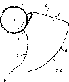
Fig. 1 is the figure that sees axial fan from wing pressure surface side, and Fig. 2 is the figure that sees a fan part from wing pressure surface side, is the accompanying drawing that is used to illustrate the 1st example.
That is,,, be provided with the blade of many pieces of (being 3 pieces here) wings by certain interval integral body at wheel hub 1 side face cylindraceous as the basic comprising of axial fan, along with the rotation of blade to axial air-supply.
Be called root 2a with the wheel hub 1 whole part that is provided with continuously of above-mentioned blade 2, the rotation front side is called wing front edge 2b, the rotation rear side is called wing hinder marginal part 2c, and these wing front edges 2b outer circumference end is called wing peripheral part 2d with the end that wing hinder marginal part 2c outer circumference end is connected.
In addition, when the air-flow on the blade 2 that produces with the rotation along with axial fan was benchmark, above-mentioned wing front edge 2b was the importing direction of air, and wing hinder marginal part 2c is the outflow direction of air.The front end of constant is above-mentioned wing front edge 2b is side-prominent towards the sense of rotation of the rotary side end of root 2a.
Especially, if the profile line that the profile line that the profile line that will form wing front edge 2b is called γ, will form wing hinder marginal part 2c is called α, will form wing peripheral part 2d is called β, then Ci Shi feature is, the profile line α that forms wing hinder marginal part 2c forms the circular arc that caves in to the importing direction opposite with the outflow direction of air.
The circular arc of the profile line α of such formation wing hinder marginal part 2c is formed by 1 curve in the drawings.In addition, not limited by this, can link to each other by the curve of 2 different curvature and form yet.
Be rotated driving in case the profile line α with above-mentioned wing hinder marginal part 2c is formed the axial fan of circular-arc blade 2, even if under the situation that improves rotating speed increase air quantity, wing hinder marginal part eddy current further reduces, the loss of air-flow reduces, load on the drive motor can be suppressed less, improve the energy saving of air conditioner.
Fig. 3 is an accompanying drawing of seeing the part axial fan from wing pressure surface side, is the accompanying drawing that is used to illustrate the 2nd example.
That is, see axial fan, rotary middle point O is made as OQ with the line that the intersection point Q between the profile line β of the profile line α of wing hinder marginal part 2c and wing peripheral part 2d is connected from the plane vertical with running shaft.In addition, rotary middle point O is made as OS with the line that the point of intersection S between the profile line β of the profile line γ of wing front edge 2b and wing peripheral part 2d is connected.And the angle that is constituted between above-mentioned line segment OQ and the line segment OS is made as θ t.
In addition, be made as PG1, PG2 respectively with the line segment that 2 end points G1, G2 of circular arc are connected separately from the center of arc's point P that forms wing hinder marginal part profile line α.The angle θ k that these line segments PG1 and line segment PG2 constitute is set to 0.7~0.8 times size with respect to above-mentioned angle θ t.
Thus, the wing backwash further dwindles, and the load on the drive motor can be suppressed less.
Fig. 4 is an accompanying drawing of seeing the part axial fan from wing pressure surface side, is the accompanying drawing that is used to illustrate the 3rd example.
That is, the profile line α of wing hinder marginal part 2c be circular-arc be constant, here, its profile line is formed by the curve of 2 different curvature.
Rotary middle point O is made as OQ with the line that the intersection point Q between the profile line β of the profile line α of wing hinder marginal part 2c and wing peripheral part 2d is connected, rotary middle point O is made as OS with the line that the point of intersection S between the profile line β of the profile line γ of wing front edge 2b and wing peripheral part 2d is connected, and the angle that is constituted between above-mentioned line segment OQ and the line segment OS is made as θ t.
And, from wing peripheral part 2d side center of arc's point separately is being made as T, U, from wing peripheral part side circular arc end points separately is being made as respectively on the basis of J1, J2, J3, above-mentioned angle θ t is set to 1.3~1.5 times the size of relative angle θ m+ θ n, and angle θ m+ θ n is the angle θ n sum that angle θ m that line segment TJ1 and line segment TJ2 are constituted is constituted with line segment UJ2 and line segment UJ3.
Thus, the wing backwash further dwindles, and the load on the drive motor can be suppressed less.
Fig. 5 is an outline drawing of seeing the part axial fan from wing suction surface side, is the accompanying drawing that is used to illustrate the 4th example.
Promptly, profile line α formation profile shape with wing hinder marginal part 2c is a prerequisite, this profile line α and the intersection point that forms between the profile line β of wing peripheral part 2d are made as Q, the intersection point between the profile line β of the profile line γ of above-mentioned wing front edge 2b and wing peripheral part 2d is made as S.In addition, will the plane vertical with fan rotation axis Y be made as QY by above-mentioned intersection point Q, the plane vertical with fan rotation axis Y by point of intersection S is made as SY.
At this moment, the maximum normal distance Hk between the profile line α of plane QY and above-mentioned wing hinder marginal part is set at 10~20% scope with respect to the vertical line Hf between plane QY and the SY.
Thus, the wing backwash further dwindles, and the load of drive motor one can be suppressed less.
Fig. 6 is an accompanying drawing of seeing the part axial fan from wing pressure surface side, is the accompanying drawing that is used to illustrate the 5th example.
That is, forming the profile line α of above-mentioned wing hinder marginal part 2c, is circular arc part α 1 is set continuously, constitutes that the 2 curve part α of place 2, the α 3 of all sides and outer circumferential side forms in the fan of these circular arc both sides.
When the length with the curve part α 2 of all sides in above-mentioned is made as L1, when the length of the curve part α 3 of outer circumferential side is made as L2, sets L1 〉=L2 for.
Thus, the wing backwash further dwindles, and the load on the drive motor can be suppressed less.
Fig. 7 is an accompanying drawing of seeing the part axial fan from wing pressure surface side, is the accompanying drawing that is used to illustrate the 6th example.
That is, be a kind of along wheel hub 1 side face cylindraceous be provided with the blade 2 of many pieces of (only representing 1 piece herein) wings, with its rotation to the axial fan of axial air-supply.
Above-mentioned blade 2 has at the wing front edge 2b of the importing direction of air with at the wing hinder marginal part 2c of the outflow direction of air and the wing peripheral part 2d that forms periphery, and separately profile line is called γ, α a, β.
The feature of this moment is that the profile line α b of above-mentioned wing hinder marginal part 2c is the V word shape that forms to the importing direction depression opposite with the outflow direction of air.Even if this kind shape also can access and above-mentioned circular-arc equal effect.
Fig. 8 is an accompanying drawing of seeing the part axial fan from wing pressure surface side, is the accompanying drawing that is used to illustrate the 7th example.
That is, be a kind of along wheel hub 1 side face cylindraceous be provided with the blade 2 of many pieces of (only representing 1 piece herein) wings, with its rotation to the axial fan of axial air-supply.
Above-mentioned blade 2 has at the wing front edge 2b of the importing direction of air with at the wing hinder marginal part 2c of air stream outgoing direction and the wing peripheral part 2d that forms periphery, and separately profile line is called γ, α b, β.
The feature of this moment is that the profile line α b of the above-mentioned wing sheet edge 2c of portion is the concavity that forms to the trapezoid shaped of the importing direction depression opposite with the outflow direction of air.Even if this shape also can obtain the effect with above-mentioned circular-arc side etc.
As mentioned above, even if the present invention adopts the axial fan of arbitrary structure, under the situation that rotating speed rises, air quantity increases of gas fan, also the load on the motor can be suppressed less, when improving energy saving, can not make complex-shapedization of wing hinder marginal part, can reduce the wing area, and improve formability and reduce cost.
Claims (4)
1. axial fan is provided with the blade of many pieces of wings along wheel hub side face cylindraceous,, it is characterized in that to axial air-supply with its rotation,
Above-mentioned blade has the wing hinder marginal part that is positioned at the air stream outgoing direction, is positioned at the wing peripheral part that air imports the wing front edge of direction and forms periphery,
The profile line of above-mentioned wing hinder marginal part forms to the importing direction depression opposite with the outflow direction of air,
When being benchmark with the plane vertical with respect to running shaft, fan rotary middle point (O) is made as OQ with the line that the intersection point (Q) between the profile line (β) of the profile line (α) of wing hinder marginal part and wing peripheral part is connected, fan rotary middle point (O) is made as OS with the line that the intersection point (S) between the profile line (β) of the profile line (γ) of wing front edge and wing peripheral part is connected, the angle that is constituted between above-mentioned OQ and the OS is made as θ t, from center of arc's point (P) of wing hinder marginal part profile line separately with two end points (G1 of circular arc, G2) line segment that is connected is made as PG1 respectively, during PG2, the angle (θ k) that line segment PG1 and line segment PG2 constitute is set to 0.7~0.8 times size with respect to above-mentioned angle θ t.
2. axial fan is provided with the blade of many pieces of wings along wheel hub side face cylindraceous,, it is characterized in that to axial air-supply with its rotation,
Above-mentioned blade has the wing hinder marginal part that is positioned at the air stream outgoing direction, is positioned at the wing peripheral part that air imports the wing front edge of direction and forms periphery,
The profile line of above-mentioned wing hinder marginal part forms to the importing direction depression opposite with the outflow direction of air,
The circular arc that constitutes above-mentioned wing hinder marginal part profile line forms by the curve of two different curvature is continuous,
When being benchmark with the plane vertical with respect to running shaft, fan rotary middle point (0) is made as OQ with the line that the intersection point (Q) between the profile line (β) of the profile line (α) of wing hinder marginal part and wing peripheral part is connected, fan rotary middle point (O) is made as OS with the line that the intersection point (S) between the profile line (β) of the profile line (γ) of wing front edge and wing peripheral part is connected, when the angle that is constituted between above-mentioned OQ and the OS is made as θ t, by the formed circular arc of the curve of above-mentioned two different curvature, when center of arc's point separately is made as T, U, circular arc end points separately is made as J1, J2, during J3, the angle (θ t) that is constituted between above-mentioned OQ and the OS is configured to 1.3~1.5 times size of the line segment (UJ2) that the line segment (TJ1) that is connected with end points J1 with respect to central point T and angle (θ m) the isocenter U that is constituted the line segment (TJ2) that central point T is connected with end points J2 be connected with end points J2 and the angle (θ m+ θ n) of angle (θ n) addition that is constituted the line segment (UJ3) that central point U is connected with end points J3.
3. axial fan is provided with the blade of many pieces of wings along wheel hub side face cylindraceous,, it is characterized in that to axial air-supply with its rotation,
Above-mentioned blade has the wing hinder marginal part that is positioned at the air stream outgoing direction, is positioned at the wing peripheral part that air imports the wing front edge of direction and forms periphery,
The profile line of above-mentioned wing hinder marginal part forms to the importing direction depression opposite with the outflow direction of air,
When the intersection point between the profile line (β) of the profile line (α) of above-mentioned wing hinder marginal part and above-mentioned wing peripheral part is made as Q, intersection point between the profile line (β) of the profile line (γ) of above-mentioned wing front edge and wing peripheral part is made as S, will the plane vertical with fan rotation axis (Y) be made as QY by above-mentioned intersection point Q, when the plane vertical with fan rotation axis (Y) was made as SY by point of intersection S, the maximum normal distance (Hk) between the profile line (α) of plane QY and above-mentioned wing hinder marginal part was configured to 10~20% scope of the vertical line (Hf) between opposite planar QY and the planar S Y.
4. axial fan is provided with the blade of many pieces of wings along wheel hub side face cylindraceous,, it is characterized in that to axial air-supply with its rotation,
Above-mentioned blade has the wing hinder marginal part that is positioned at the air stream outgoing direction, is positioned at the wing peripheral part that air imports the wing front edge of direction and forms periphery,
The profile line of above-mentioned wing hinder marginal part forms to the importing direction depression opposite with the outflow direction of air,
The profile line of above-mentioned wing hinder marginal part is above-mentioned concavity portion to be set continuously and all sides and outer circumferential side two places form in fan shoulder forms, and when the shoulder length that is made as L1, outer circumferential side when the shoulder length with all sides in above-mentioned is made as L2, be set to L1 〉=L2.
Applications Claiming Priority (3)
| Application Number | Priority Date | Filing Date | Title |
|---|---|---|---|
| JP062002/2001 | 2001-03-06 | ||
| JP2001062002A JP2002257088A (en) | 2001-03-06 | 2001-03-06 | Axial flow fan |
| JP062002/01 | 2001-03-06 |
Publications (2)
| Publication Number | Publication Date |
|---|---|
| CN1374460A CN1374460A (en) | 2002-10-16 |
| CN1195943C true CN1195943C (en) | 2005-04-06 |
Family
ID=18921214
Family Applications (1)
| Application Number | Title | Priority Date | Filing Date |
|---|---|---|---|
| CNB021069476A Expired - Lifetime CN1195943C (en) | 2001-03-06 | 2002-03-06 | Tube-axial fan |
Country Status (3)
| Country | Link |
|---|---|
| JP (1) | JP2002257088A (en) |
| KR (1) | KR100461901B1 (en) |
| CN (1) | CN1195943C (en) |
Cited By (1)
| Publication number | Priority date | Publication date | Assignee | Title |
|---|---|---|---|---|
| CN102003412A (en) * | 2010-12-03 | 2011-04-06 | 陈新 | Wing shaped blade of high-pressure axial fan |
Families Citing this family (16)
| Publication number | Priority date | Publication date | Assignee | Title |
|---|---|---|---|---|
| JP2004301451A (en) * | 2003-03-31 | 2004-10-28 | Toshiba Kyaria Kk | Outdoor machine for air conditioner |
| JP4374897B2 (en) | 2003-05-12 | 2009-12-02 | 株式会社日立製作所 | Axial fan |
| JP2007107530A (en) * | 2006-11-16 | 2007-04-26 | Toshiba Kyaria Kk | Axial flow fan |
| CN100465458C (en) * | 2007-01-31 | 2009-03-04 | 广东美的电器股份有限公司 | Axial-flow windwheel |
| CN103511339B (en) * | 2012-06-29 | 2016-02-03 | 珠海格力电器股份有限公司 | Air-conditioning, axial-flow blower and axial-flow leaf thereof |
| JP6066691B2 (en) * | 2012-11-26 | 2017-01-25 | 株式会社サムスン日本研究所 | Propeller fan and air conditioner using the propeller fan |
| EP2943726B1 (en) * | 2013-01-11 | 2023-03-01 | Carrier Corporation | Air handling unit |
| US20160003487A1 (en) * | 2013-02-22 | 2016-01-07 | Hitachi Appliances, Inc. | Propeller Fan and Air Conditioner Equipped with the Same |
| WO2015092924A1 (en) * | 2013-12-20 | 2015-06-25 | 三菱電機株式会社 | Axial flow fan |
| CN105927586B (en) * | 2016-06-03 | 2018-05-11 | 华中科技大学 | The Start-stop control leaf and its modified method of a kind of remodeling |
| CN106640748B (en) * | 2017-01-06 | 2022-12-02 | 珠海格力电器股份有限公司 | Blade, impeller and fan |
| KR102109371B1 (en) * | 2018-01-15 | 2020-05-12 | 주식회사 경인기계 | Fan and cooling tower comprising the same |
| CN110332149B (en) * | 2019-07-25 | 2024-03-12 | 洛阳北玻三元流风机技术有限公司 | Axial flow fan convenient to simulate aerial flying man through gas thrust |
| CN113757168A (en) * | 2020-06-01 | 2021-12-07 | 广东美的白色家电技术创新中心有限公司 | Fan blade, fan, air condensing units and air conditioning system |
| CN114645871A (en) * | 2020-12-18 | 2022-06-21 | 青岛海尔空调电子有限公司 | Axial-flow impeller, axial-flow fan with same and air conditioner |
| CN114673687B (en) * | 2022-05-30 | 2022-08-19 | 长城汽车股份有限公司 | Fan blade assembly, fan and vehicle |
Family Cites Families (9)
| Publication number | Priority date | Publication date | Assignee | Title |
|---|---|---|---|---|
| JPS5181006A (en) * | 1975-01-14 | 1976-07-15 | Matsushita Seiko Kk | SOFUKINO HANEGURUMA |
| JPS59173598A (en) * | 1983-03-23 | 1984-10-01 | Nippon Denso Co Ltd | Axial fan |
| JPS60114300U (en) * | 1984-12-13 | 1985-08-02 | トリン コーポレーシヨン | axial flow wheel |
| JPH0842497A (en) * | 1994-07-28 | 1996-02-13 | Matsushita Electric Ind Co Ltd | Impeller of axial flow blower |
| JPH08121386A (en) * | 1994-10-31 | 1996-05-14 | Fuji Kogyo Kk | Propeller fan |
| JP3448136B2 (en) * | 1994-11-08 | 2003-09-16 | 三菱重工業株式会社 | Propeller fan |
| KR0141761B1 (en) * | 1995-09-01 | 1998-07-01 | 구자홍 | Wind direction variable device of axial flow fan |
| US5961289A (en) * | 1995-11-22 | 1999-10-05 | Deutsche Forshungsanstalt Fur Luft-Und Raumfahrt E.V. | Cooling axial flow fan with reduced noise levels caused by swept laminar and/or asymmetrically staggered blades |
| JP3604533B2 (en) * | 1997-05-30 | 2004-12-22 | 株式会社東芝 | Wing for axial compressor |
-
2001
- 2001-03-06 JP JP2001062002A patent/JP2002257088A/en active Pending
-
2002
- 2002-03-06 CN CNB021069476A patent/CN1195943C/en not_active Expired - Lifetime
- 2002-03-06 KR KR10-2002-0011826A patent/KR100461901B1/en not_active IP Right Cessation
Cited By (2)
| Publication number | Priority date | Publication date | Assignee | Title |
|---|---|---|---|---|
| CN102003412A (en) * | 2010-12-03 | 2011-04-06 | 陈新 | Wing shaped blade of high-pressure axial fan |
| CN102003412B (en) * | 2010-12-03 | 2014-04-02 | 陈新 | Wing shaped blade of high-pressure axial fan |
Also Published As
| Publication number | Publication date |
|---|---|
| KR100461901B1 (en) | 2004-12-17 |
| JP2002257088A (en) | 2002-09-11 |
| KR20020071756A (en) | 2002-09-13 |
| CN1374460A (en) | 2002-10-16 |
Similar Documents
| Publication | Publication Date | Title |
|---|---|---|
| CN1195943C (en) | Tube-axial fan | |
| CN1712733A (en) | Eccentric fan and air conditioner therewith | |
| CN1139731C (en) | Axial flow fan | |
| CN1993556A (en) | A high efficiency axial fan | |
| CN1847669A (en) | Air feeder vane wheel | |
| CN1723348A (en) | Engine-cooling fan assembly with overlapping fans | |
| CN1083947C (en) | Impeller for centrifugal fan | |
| CN1752457A (en) | Blower impeller | |
| CN1782440A (en) | Cross flow fan and indoor unit of air conditioner with cross flow fan | |
| EP1825148A1 (en) | Axial fan | |
| CN1278048C (en) | Impeller, blower and freezing-cooling storeroom | |
| CN1417481A (en) | Blower vane wheel for air conditioner | |
| CN100343590C (en) | Outdoor unit for air conditioner | |
| CN104791301B (en) | One kind is curved to plunder aluminium alloy axial blade | |
| CN2864177Y (en) | Radiation fan | |
| CN112228395B (en) | Axial flow fan blade and air conditioner | |
| CN1201090C (en) | Blower and air conditioner with the same | |
| CN1265100C (en) | Cross flow fan | |
| CN202418036U (en) | Axial flow fan and air conditioner with same | |
| CN213775738U (en) | Axial flow fan for air conditioner outdoor unit and air conditioner outdoor unit | |
| CN201258874Y (en) | Fan blade in axial fan | |
| CN1258042C (en) | Horizontal flow fan and air conditioner using same | |
| CN212959244U (en) | Energy-saving emission-reducing flexible and universal through-flow scroll fan | |
| CN2454571Y (en) | Centrifugal air blower | |
| CN113847275B (en) | Wing type axial flow fan blade and air conditioner external unit |
Legal Events
| Date | Code | Title | Description |
|---|---|---|---|
| C10 | Entry into substantive examination | ||
| SE01 | Entry into force of request for substantive examination | ||
| C06 | Publication | ||
| PB01 | Publication | ||
| C10 | Entry into substantive examination | ||
| SE01 | Entry into force of request for substantive examination | ||
| C14 | Grant of patent or utility model | ||
| GR01 | Patent grant | ||
| CX01 | Expiry of patent term | ||
| CX01 | Expiry of patent term |
Granted publication date: 20050406 |