CN1174631C - Apparatus and method for partial buffering transmitted data to provide robust error recovery in lossy transmission environment - Google Patents
Apparatus and method for partial buffering transmitted data to provide robust error recovery in lossy transmission environment Download PDFInfo
- Publication number
- CN1174631C CN1174631C CNB988125919A CN98812591A CN1174631C CN 1174631 C CN1174631 C CN 1174631C CN B988125919 A CNB988125919 A CN B988125919A CN 98812591 A CN98812591 A CN 98812591A CN 1174631 C CN1174631 C CN 1174631C
- Authority
- CN
- China
- Prior art keywords
- data
- buffer
- piece
- bit
- coded
- Prior art date
- Legal status (The legal status is an assumption and is not a legal conclusion. Google has not performed a legal analysis and makes no representation as to the accuracy of the status listed.)
- Expired - Fee Related
Links
Images


Classifications
-
- H—ELECTRICITY
- H04—ELECTRIC COMMUNICATION TECHNIQUE
- H04N—PICTORIAL COMMUNICATION, e.g. TELEVISION
- H04N19/00—Methods or arrangements for coding, decoding, compressing or decompressing digital video signals
- H04N19/50—Methods or arrangements for coding, decoding, compressing or decompressing digital video signals using predictive coding
- H04N19/59—Methods or arrangements for coding, decoding, compressing or decompressing digital video signals using predictive coding involving spatial sub-sampling or interpolation, e.g. alteration of picture size or resolution
-
- H—ELECTRICITY
- H04—ELECTRIC COMMUNICATION TECHNIQUE
- H04N—PICTORIAL COMMUNICATION, e.g. TELEVISION
- H04N19/00—Methods or arrangements for coding, decoding, compressing or decompressing digital video signals
- H04N19/85—Methods or arrangements for coding, decoding, compressing or decompressing digital video signals using pre-processing or post-processing specially adapted for video compression
- H04N19/88—Methods or arrangements for coding, decoding, compressing or decompressing digital video signals using pre-processing or post-processing specially adapted for video compression involving rearrangement of data among different coding units, e.g. shuffling, interleaving, scrambling or permutation of pixel data or permutation of transform coefficient data among different blocks
-
- H—ELECTRICITY
- H04—ELECTRIC COMMUNICATION TECHNIQUE
- H04N—PICTORIAL COMMUNICATION, e.g. TELEVISION
- H04N19/00—Methods or arrangements for coding, decoding, compressing or decompressing digital video signals
- H04N19/85—Methods or arrangements for coding, decoding, compressing or decompressing digital video signals using pre-processing or post-processing specially adapted for video compression
- H04N19/89—Methods or arrangements for coding, decoding, compressing or decompressing digital video signals using pre-processing or post-processing specially adapted for video compression involving methods or arrangements for detection of transmission errors at the decoder
- H04N19/895—Methods or arrangements for coding, decoding, compressing or decompressing digital video signals using pre-processing or post-processing specially adapted for video compression involving methods or arrangements for detection of transmission errors at the decoder in combination with error concealment
-
- H—ELECTRICITY
- H04—ELECTRIC COMMUNICATION TECHNIQUE
- H04N—PICTORIAL COMMUNICATION, e.g. TELEVISION
- H04N19/00—Methods or arrangements for coding, decoding, compressing or decompressing digital video signals
- H04N19/90—Methods or arrangements for coding, decoding, compressing or decompressing digital video signals using coding techniques not provided for in groups H04N19/10-H04N19/85, e.g. fractals
- H04N19/98—Adaptive-dynamic-range coding [ADRC]
-
- H—ELECTRICITY
- H04—ELECTRIC COMMUNICATION TECHNIQUE
- H04N—PICTORIAL COMMUNICATION, e.g. TELEVISION
- H04N7/00—Television systems
- H04N7/24—Systems for the transmission of television signals using pulse code modulation
- H04N7/52—Systems for transmission of a pulse code modulated video signal with one or more other pulse code modulated signals, e.g. an audio signal or a synchronizing signal
-
- H—ELECTRICITY
- H04—ELECTRIC COMMUNICATION TECHNIQUE
- H04N—PICTORIAL COMMUNICATION, e.g. TELEVISION
- H04N21/00—Selective content distribution, e.g. interactive television or video on demand [VOD]
- H04N21/40—Client devices specifically adapted for the reception of or interaction with content, e.g. set-top-box [STB]; Operations thereof
- H04N21/41—Structure of client; Structure of client peripherals
- H04N21/426—Internal components of the client ; Characteristics thereof
-
- H—ELECTRICITY
- H04—ELECTRIC COMMUNICATION TECHNIQUE
- H04N—PICTORIAL COMMUNICATION, e.g. TELEVISION
- H04N5/00—Details of television systems
- H04N5/14—Picture signal circuitry for video frequency region
- H04N5/21—Circuitry for suppressing or minimising disturbance, e.g. moiré or halo
Abstract
A system and method for buffering a plurality of divisions of a signal prior to transmission of the signal is disclosed. The buffering (800) is configured to prevent error propagation during decoding of the transmitted signal. A set of encoding levels at a transmission rate is selected from a threshold table having a plurality of encoding levels. Each set of encoding levels includes a plurality of ranges configured to select encoding bits. Each division of the signal is encoded using the set of encoding levels. In one embodiment, this is used in the transmission of video signals over a potentially lossy communications channel.
Description
Background of invention
1. related application
The application is the U.S. Patent Application Serial No.09/016 that is entitled as " Source Coding toProvide for Robust Error Recovery During Transmission Losses (source encoding of the mistake recovery of enhancing is provided) " when loss that submitted on January 30th, 1998,083 continuation application, and it is the application serial no No.09/002 of being entitled as of submitting on January 2nd, 1998 " Image-to-Block Mapping to Provide for Robust Error RecoveryDuring Transmission Losses (provide when loss the image that the mistake of enhancing recovers-to-piece mapping) ", 547, the application serial no No.09/002 that is entitled as " Source Coding to Provide for Robust Error RecoveryDuring Transmission Losses (source encoding of the mistake recovery of enhancing is provided) " when loss that on January 2nd, 1998 submitted to, 470, and the application serial no No.09/002 of being entitled as of submitting on January 2nd, 1998 " Multiple Block Based Recovery Method to Provide forRobust Error Recovery During Transmission Losses (when loss, provide the mistake of enhancing recover based on the polylith restoration methods) ", 553 part continuation application; They are application serial no No.08/965 of being entitled as of submitting on October 23rd, 1997 " Image-to-Block Mapping to Provide for Robust Error RecoveryDuring Transmission Losses (provide when loss the image that the mistake of enhancing recovers-to-piece mapping) ", 632, the application serial no No.08/957 that is entitled as " Source Coding to Provide for Robust ErrorRecovery During Transmission Losses (source encoding of the mistake recovery of enhancing is provided) " when loss that on October 23rd, 1997 submitted to, 555, and the application serial no No.08/956 of being entitled as of submitting on October 23rd, 1997 " Multiple Block Based Recovery Method toProvide for Robust Error Recovery During Transmission Losses (when loss, provide the mistake of enhancing recover based on the polylith restoration methods) ", 870 part continuation application.The application serial no No.09/016 that on January 30th, 1998 submitted to, 083, the application serial no No.09/002 that submitted on January 2nd, 1998,547, the application serial no No.09/002 that submitted on January 2nd, 1998,470, the application serial no No.09/002 that submitted on January 2nd, 1998,553, the application serial no No.08/956 that submitted on October 23rd, 1997,632, the application serial no No.08/957 that submitted on October 23rd, 1997, the application serial no No.08/956 that on October 23rd, 555 and 1997 submitted to, 870 all here in conjunction with reference.
2. invention field
The present invention relates to providing the recovery of enhancing owing to occurring mistake that data loss brings in the signals transmission.
3. technical background
There are a lot of technology to be used for reconstruct owing to the obliterated data that random error causes appears in signals transmission.But these technology can not be handled losing of continuous data grouping.Being lost in continuously of packet is described in the art for burst error.Burst error causes the very significantly reconstruction signal quality decline to the end user.In addition, be used to promote that the compression method of high-speed communication makes the caused signal decline of burst error become more serious, therefore make reconstruction signal become poorer.Influence send and/or the example of the burst error loss of storage signal therein compression method played high definition TV (" the HDTV ") signal of important function and mobile communication and can see in using.
The higher resolution of standard of being advised than present National TelevisionSystems Committee (" NTSC " national television system committee) is introduced television system in the appearance of HDTV.The HDTV signal of being advised mainly is digital.Therefore, when colour TV signal was converted to the numeral use, it was common that luminance and chrominance information is used eight digital bitizations.The Digital Transmission of color TV requires the nominal bit rate of per second 216 megabits.The transmission rate of HDTV is higher, requires to its nominal about per second 1200 megabits.This high transfer rate substantially exceeds the bandwidth that the current wireless standard is supported.Therefore, require effective compression method.
Compression method also plays an important role in mobile communication is used.Usually, packet is transmitted between the remote terminal that mobile communication is used.A limited number of transmission channel requires to have effective compression method before the transmitted in packets in the mobile communication.Multiple compression method is used to promote high transfer rate.
Adaptive dynamic range coding (" ADRC ") and discrete cosine transform (" DCT ") coding provide image compression technology known in the art.Two kinds of technology have all utilized visual interior local correlations to realize high compression ratio.But effectively compression algorithm causes more serious error propagation, because the mistake in the code signal is more remarkable when decoding subsequently.This wrong breeding causes the very significantly video image quality decline to the user.
Brief summary of the invention
The invention describes method to the signal source encoding.Particularly, the signal that comprises a plurality of signal elements is handled.Each signal element formation bit stream that is encoded.Bit in the given bit stream is dispersed in the different bit streams.Therefore, the parameter of description segment unit composition is dispersed in the different bit streams.Dispersion steps lead to errors be distributed to multistage in.Therefore, when dispersion steps by decoder, inverse when carrying out, the burst transfer mistake becomes the local loss group of dispersion.
Also describe another kind and be used for the method that multistage shuffling (shuffling) handled.Signal is defined as multistage, and wherein each rank comprises a plurality of frames, a plurality of pixel and a plurality of bit.In one embodiment, shuffle appear at each the level and the level between.Multistage shuffle make the burst error loss be dispersed to multistage in, therefore help occurring the image reconstruction of the image region of loss.
A kind of method that during decoding, limits the code signal of error propagation, this method comprises:
This signal is divided into a plurality of data segments;
Each data segment is stored at least one buffer;
Determine obtainable bit number based on the transmission rate of expectation with as the length of at least one buffer of storing this data segment as coded-bit;
Selection be used to the to encode thresholding group of each data segment, this thresholding group has a plurality of scopes, different number of coded bits of each range assignment in these a plurality of scopes, the number of coded bits that wherein is allocated for each data segment of coding is not more than obtainable bit number; And
Use this thresholding group this data segment of encoding.
A kind of method that limits the decoded data of error propagation, this method comprises:
Received code data at least one buffer, this coded data comprises according to selected thresholding group comes the coded data section, this thresholding group has a plurality of scopes, the number of coded bits that each range assignment is different, this number of coded bits that wherein is assigned with is not more than obtainable bit number, based on the length that the transmission rate and being used to of expectation is stored the buffer of data segment, this obtainable bit number is as coded-bit;
The recovery that determines whether the coded data in the buffer is under an embargo; And
Decode if the recovery of data is not under an embargo coded data in this buffer.
A kind of digital processing system that comprises processor, dispose this digital processing system with code signal, so that during decoding, limit error propagation, dispose described processor so that this signal is divided into a plurality of data segments, this each data segment is stored at least one buffer, the length of storing the buffer of this data segment based on the transmission rate and being used to of expectation determines to be used as the obtainable bit number of coded-bit, selection be used to the to encode thresholding group of each data segment, this thresholding group has a plurality of scopes, the number of coded bits that each range assignment is different, the number of coded bits that wherein is allocated for each data segment of coding is not more than obtainable bit number, and uses this thresholding group this data segment of encoding.
A kind of digital processing system that comprises processor, dispose this digital processing system with decoded data, so that restriction error propagation, dispose described processor with received code data at least one buffer, this coded data comprises according to selected thresholding group comes the coded data section, this thresholding group has a plurality of scopes, the number of coded bits that each range assignment is different, the number of coded bits that wherein is assigned with is not more than obtainable bit number, this obtainable bit number is the coded-bit as the length of the buffer of storing this data segment based on the transmission rate and being used to of expectation, determine whether to forbid the recovery of the coded data in the buffer, and if the recovery of these data be not under an embargo then this coded data in the decode buffer.
A kind of device that during decoding, limits the code signal of error propagation, this device comprises:
The device that this signal is divided into a plurality of data segments;
Each data segment is stored in device at least one buffer;
Based on the transmission rate of expectation with determine to be used as the device of the obtainable bit number of coded-bit as the length of at least one buffer of this data segment of storage;
Selection be used to the to encode device of thresholding group of each data segment, this thresholding group has a plurality of scopes, and different number of coded bits of each range assignment is not more than obtainable bit number so that be allocated for the number of coded bits of each data segment of coding; And
Use the encode device of this data segment of this thresholding group.
A kind of device that limits the decoded data of error propagation, this device comprises:
Be used for device at least one buffer received code data;
Determine whether the forbidden device of recovery of the coded data in the buffer; And
The device of the interior coded data of this buffer of decoding if the recovery of data is not under an embargo, wherein this coded data comprises according to selected thresholding group and comes the coded data section, this thresholding group has a plurality of scopes, the number of coded bits that each range assignment is different, this number of coded bits that wherein is assigned with is not more than obtainable bit number, based on the length that the transmission rate and being used to of expectation is stored the buffer of data segment, this obtainable bit number is as coded-bit.
Brief description of the drawings
Those skilled in the art according to following detailed description with clear and definite purpose of the present invention, characteristic and advantage, wherein:
Fig. 1 generality has illustrated signal encoding, transmission and decode procedure.
Fig. 2 has illustrated an embodiment of packet configuration.
Fig. 3 is a flow chart, and an embodiment of the cataloged procedure of the notion according to the present invention is described.
Fig. 4 is a flow chart, and an embodiment of the decode procedure of the notion according to the present invention is described.
An embodiment of the image of Fig. 5 explanation notion-arrive-piece mapping according to the present invention.
An embodiment of the shuffle mode of Fig. 5 a explanation image-use in-piece the mapping.
Fig. 6 illustrates the complementation and the interlocking block structure of demonstration.
An embodiment of the shuffle mode of Y piece in Fig. 7 a, 7b, 7c and the combination of 7d explanation frame.
Fig. 8 illustrates the embodiment that the accumulative total DR of buffer 0 distributes.
An embodiment of Fig. 8 a explanation part shuffle process of notion according to the present invention.
An embodiment of YUV piece shuffle process in the buffer of Fig. 9 explanation notion according to the present invention.
An embodiment of VL data shuffle process in the group of Figure 10 explanation notion according to the present invention.
An embodiment of the Q sign indicating number cascade in the 3-piece combination of Figure 11 explanation notion according to the present invention.
An embodiment of the Q sign indicating number cascade that the frame that comprises moving mass of Figure 11 a explanation notion according to the present invention is right.
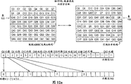
Figure 12 illustrates an embodiment of the pixel data mistake that 1/6 burst error loss causes.
Figure 12 a explanation notion the Q sign indicating number is shuffled and an embodiment of the Q sign indicating number bit that distributes according to the present invention.
An embodiment of the caused pixel data mistake of 1/6 burst error loss of Figure 12 b explanation redistribution Q sign indicating number.
An embodiment of the caused pixel data mistake of 1/6 burst error loss of Q sign indicating number is reassigned in Figure 12 c explanation.
The embodiment that the MIN of Figure 13 explanation notion according to the present invention shuffles.
Figure 13 a explanation indicates an embodiment who shuffles with the fixed-length data loss a frame centering motion.
Figure 14 illustrates the embodiment that delivery shuffles.
Figure 14 a explanation is shuffled the embodiment that relevant delivery shuffles result and fixed-length data loss with delivery.
Figure 14 b explanation is shuffled another embodiment that relevant delivery shuffles result and fixed-length data loss with delivery.
Figure 14 c explanation is shuffled another embodiment that relevant delivery shuffles result and fixed-length data loss with delivery.
Figure 15 illustrates an embodiment of variable length data buffer memory in the frame combination.
Figure 16 has illustrated embodiment that the intersegmental VL-data of the notion according to the present invention are shuffled.
Figure 17 is the flow graph of an embodiment of general explanation data recovery process of the present invention.
Figure 18 is the flow graph of a Q bit of the present invention and an embodiment of motion sign recovery process.
Figure 19 is the decode table of an embodiment of explanation candidate.
The embodiment of used measurement in the Q bit of Figure 20 a, 20b, 20c, 20d explanation Figure 18 and the motion sign recovery process.
Figure 21 explanation is used for an embodiment of the table of the Q bit of Figure 18 and definite square-error probability function that motion indicates recovery process.
An embodiment of the Q bit of Figure 22 explanation notion, motion sign and supplementary recovery process according to the present invention.
Figure 23 illustrates the use of postamble among the embodiment of two-way Q bit and motion sign recovery process.
Another embodiment of Figure 24 a, 24b and the decoding of 24c explanation evaluate candidate.
Figure 25 is the use of the level and smooth measure of conceptual illustration according to an embodiment of the invention.
Another embodiment of Figure 26 a, 26b, 26c, 26d and 26e explanation evaluate candidate decode procedure.
Another process of Figure 27 a explanation evaluate candidate decoding, an embodiment of weighted value is determined in Figure 27 b explanation.
Describe in detail
The invention provides a kind of coding and arrange signal flow so that the method that provides the mistake of enhancing to recover.In the following description, for the purpose of illustrating, a lot of details have been proposed, so that provide to complete understanding of the present invention.But, it should be apparent that for those skilled in the art these specific details are that enforcement the present invention is unnecessary.On the other hand, well-known electrical structure and circuit are represented with the form of block diagram, so just can make the present invention become unintelligible necessarily.
Signal processing method and structure are to be that the angle of vision signal such an embodiment is described from signal.But method described herein and device are to wish to be applied to various types of signals, comprise voice signal or other digital data bit stream, and wherein each signal is made up of a plurality of signal elements.In addition, Processing Example described herein uses adaptive dynamic range coding (" ADRC ") process to come packed data; But also can use various coding techniquess and algorithm.For more going through of ADRC, can be referring to " Adpative Dynamic Range CodingScheme for Future HDTV Digital VTR (the adaptive dynamic range encoding scheme of following HDTV digital video) ", Kondo, Fujimori and Nakaya, FourthInternational Workshop on HDTV and Beyond,-6 days on the 4th September in 1991, Turin, Italy.
In above-mentioned article, three kinds of dissimilar ADRC have been explained.They are all realized according to following formula:
Non-edge coupling ADRC:
DR=MAX-MIN+ 1
Edge coupling ADRC:
DR=MAX-MIN
Multistage ADRC:
DR=MAX-MIN+ 1
Here MAX ' is at q=2
QThe mean value of x ' under-1 situation; MIN ' is the mean value of x ' under the q=0 situation; And
DR'=MAX'-MIN'
Here MAX represents the highest level of a piece, MIN represents one minimum rank, x represents the signal level of each sampling, Q represents quantizing bit number, q represents quantization code (coded data), x ' represents the decoding rank of each sampling, and square brackets [] are represented the brachymemma computing of carrying out on the interior value of square brackets.
Signal decoding, transmission and decode procedure subsequently illustrate in Fig. 1 prevailingly.Signal 100 is data flow of input coding device 110.Encoder 110 follow adaptive dynamic range coding (" ADRC ") compression algorithm and along transmission medium 135 produce grouping 1 ..., N.Decoder 120 from transmission medium 135 receive grouping 1 ..., N, and produce signal 130.Signal 130 is the reconstruct of signal 100.
In the present embodiment, the color video image that signal 100 is made up of sequence of frames of video, each frame comprise the information of representing image in the interlaced scanning video system.Each frame is made up of two fields, and a field comprises the data of visual even number line, and another comprises the data of visual odd-numbered line.Data comprise the pixel value of describing the color composition of relevant position in the image.For example, in the present invention, color composition is made up of brightness signal Y and color difference signal U and V.Obviously, process of the present invention can be used for interlaced video signal other signal in addition.In addition, obviously the invention is not restricted to the realization in Y, U, the V color space, but can be used for the image that other color space is represented.
Return with reference to figure 1, encoder 110 separates Y, U and V signal, and handles every group of signal independently according to the ADRC algorithm respectively.Discuss simply in order to make, the processing of Y-signal has been described in following narration, but coding step will repeat U and V signal.
In the present embodiment, encoder 110 is formed three-dimensional bits (" 3D ") with the Y-signal of two successive frames of leap of signal 100, and it is right to be called a frame here.For an embodiment, the 3D piece is by producing the combination of two 2D pieces of last same regional area from given frame, wherein two-dimentional 2D piece by in the frame or in local pixel combination produce.Wish that process described herein can be used for different block structures.Signal combination will be below image-in-piece mapping part, further describe.
Continue present embodiment,, whether have variation in the pixel value that encoder 110 calculates between the 2D piece that constitutes the 3D piece for given 3D piece.If change really in the value, the motion sign just is set.As known in the art, when each frame internally had local image to repeat, the use of motion sign made encoder 110 reduce the number of quantization code.Encoder 110 also detects maximum pixel intensity level (" MAX ") and the minimum pixel intensity level (" MIN ") in the 3D piece.Utilization value MAX and MIN, encoder 110 calculates the dynamic range (" DR ") of given 3D data block.For an embodiment, DR=MAX-MIN+ 1 under non-edge coupling ADRC situation.For edge coupling ADRC, DR=MAX-MIN.In another embodiment, encoder 110 is frame by frame to representing the frame stream signal encoding of a string frame of video.In another embodiment, encoder 110 flows signal encoding by the place to the territory of representing a string visual domain.Therefore, do not use the motion sign, but the 2D piece is used to calculate MIN, MAX and DR value.
In the present embodiment, encoder 110, is counted so that be identified for the quantization bit (" Q bit ") of pairing interior pixel of encoding D R with reference to calculated DR at a thresholding table (not shown).Pixel coder is produced quantization code (" Q sign indicating number ").The Q sign indicating number is to be used to store or the pictorial data of the relative compression transmitted.
In one embodiment, the selection of Q bit is what to obtain from the DR of 3D piece.Therefore, all pixels in the given 3D piece use identical Q bit to encode, to obtain a 3D encoding block.The set of the Q sign indicating number of 3D encoding block, MIN, motion sign and DR is called 3D ADRC piece.Perhaps, to the 2D block encoding, and the set of Q sign indicating number, MIN and the DR of given 2D piece produces the 2DADRC piece.
Can realize a plurality of thresholding tables.In one embodiment, the thresholding table is made up of delegation's DR threshold value.The Q bit is corresponding to the quantizing bit number that is used for the cover DR value between two adjacent DR in the thresholding table delegation is encoded.In another embodiment, the thresholding table comprises multirow, and the selection of row is according to required transmission rate.Each row in the thresholding table identifies with the thresholding index.When discussing partial buffering below, the detailed description of the embodiment that thresholding is selected describes.ADRC coding and further describing of buffer memory are transferring assignee of the present invention's the U.S. Patent No. 4 that is entitled as " HighEfficiency Coding Apparatus (high efficient coding device) ", 722,003 and the U.S. Patent No. 4 that is entitled as " High Efficiency Coding Apparatus (high efficient coding device) " equally, disclose in 845,560.
The Q sign indicating number is called as variable length data (" VL-data ") thus.In addition, DR, MIN and motion sign are called the piece attribute.Fixed-length data (" FL-data ") formed in piece attribute and thresholding index.In addition, consider top discussion, term piece attribute description the parameter relevant with the composition of signal element, wherein signal element comprises a plurality of compositions.In another embodiment, the Q bit code is drawn together in the FL-packet.Its benefit is that the Q bit information needn't obtain from DR in decode procedure.Therefore, if DR information dropout or damage, the Q bit information can also be determined from the Q bit code.In addition, if the Q bit code is lost or damaged, the Q bit information can obtain from DR.Therefore, reduced the requirement that recovers DR and Q bit.
The shortcoming that requirement is included the Q bit code is that each ADRC piece will send additional bit.But in one embodiment, the Q bit code that is used to make up the ADRC piece is merged according to for example addition or the such function of cascade.For example, if the ADRC piece is formed three groups, and if the Q bit value of each ADRC piece be respectively 3,3 and 4, the total value that then is encoded to the FL-data is 11.Therefore, represent the required bit number of summation to be less than and represent each independent required bit number of value, and the Q bit value that does not have in the group to damage can be used for determining the Q bit value and needn't carry out the sort of Q bit recovery processing that describes below.
Also considered other embodiment.For example, motion marker data also can be encoded.Can produce the sign that has Q bit and motion marker data and use it for and search code table.The configuration and the function of coding can become according to application.
Frame, piece attribute and VL-data description the various compositions in the vision signal.The border of these compositions, position and quantity depend on transmission of video signals and compression property.In the present embodiment, these compositions are variable and shuffled in the vision signal bit stream, so that the mistake that strengthens when guaranteeing loss is recovered.
For the purpose of illustrating, regulation 1/6 continuous transmitted in packets allowable shrinkage is below described, follow video signal A DRC and encode and shuffle.Therefore, following composition definition and division are used among the embodiment.Also considered other embodiment.A data set comprises the data-signal of a part or other type of a video data.Therefore, in one embodiment, a frame set is a class data acquisition system that comprises one or more successive frames.A section comprises the memory that can store the Q sign indicating number of 1/6 part and be included in the piece attribute in the frame set.In addition, buffer comprises the memory that can store the Q sign indicating number of 1/60 part and be included in the piece attribute in the frame set.Data shuffle by in the exchange section and/or the one-tenth in the buffer assign to carry out.After this, the data in the section of being stored in are used to produce the packet for transmission.Therefore, in the following description, if section is lost, all groupings that produce from section are all lost in transmission.Similarly, if part section is lost, being grouped in the transmission of the respective number that produces from section so lost.
Although below describing to have mentioned with the ADRC coded data has 1/6 continuous packet loss, consider that method and apparatus described herein can be used for being applied to the design of the continuous packet loss tolerance of 1/n in the various coding/decoding schemes.
Fig. 2 has illustrated an embodiment who is used at the packet configuration 200 of point-to-point connection and network transmission data.Packet configuration 200 is produced by encoder 110 and sends by transmission medium 135.For an embodiment, packet configuration 200 comprises 5 word byte headers, 8 DR bits, 8 MIN bits, motion flag bit, 5 thresholding index bits and 354 bit Q sign indicating numbers.Packet configuration described herein is illustrative, and so that can be used for the transmission of asynchronous transfer mode (" ATM ") network.But, the invention is not restricted to described packet configuration, and can use various packet configurations used in the diverse network.
As what notice previously, transmission medium (for example, media) 135 is not believed to provide error free transmission, and therefore grouping may lose or damage.As what notice previously, exist and detect this conventional method of losing or damaging, worsen but image in fact generally can occur.Therefore system and method for the present invention instructed from this lose or damages strengthen the source encoding of recovery.Suppose that in whole following discussion burst loss (that is, what several successive was divided into groups loses) is most probable ill-formalness, but some random packet losses may occur also.
In order to ensure the recovery that strengthens from one or more continuous data packet loss, system and method for the present invention provides multistage and has shuffled.Particularly, be included in FL-data and VL-data in the grouping of being transmitted and comprise data on the Data Position that room and time separates.Data are shuffled guarantee that any burst error is disperseed and help mistake to recover.As following described, shuffle piece attribute and Q bit value are recovered.
Data encoding/decoding
Fig. 3 is the flow graph of the performed embodiment of cataloged procedure of explanation encoder 110.Fig. 3 has also described the general introduction of the process of shuffling of the mistake recovery that is used to prevent the image deterioration and helps strengthening.
In the step 1 of Fig. 3, an incoming frame set that is also referred to as the demonstration composition is extracted, so that reduce transmission requirement.Y-signal is drawn into 3/4 of original width by level, U and V signal each be drawn into original height 1/2 and original width 1/2.Obtain the video format of 3:1:0 like this, each frame centering has 3960 Y pieces, 660 U pieces and 660 V pieces.As what notice previously, discussion will be described the processing of Y-signal; But this processing can be used for U and V signal.In step 2, two Y frame images are mapped to the 3D piece.In step 3, the 3D piece is shuffled.In step 4, use ADRC buffer memory and coding.In step 5, the Y of coding, U and V piece shuffle in buffer.
In step 6, the VL-data of a group coding 3D piece and their corresponding piece attributes are shuffled.In step 7, the FL-data are shuffled on different sections.In step 8, carry out postamble and fill, wherein the variable spaces at buffer end has been filled predetermined bit stream.In step 9, the VL-data are shuffled on different sections.
For the purpose of illustrating, below shuffling to describe provides before coding and the method for processed pixels data afterwards.For an alternative embodiment, independently data value is shuffled/is gone by hardware and shuffled.Particularly, hardware arrives different addresses with piece value map addresses, so that realize shuffling/going shuffle process.But map addresses is impossible for value associated with the data, because shuffle the processing that must observe data.The VL-data are shuffled and are comprised value associated with the data in the group that describes below.In addition, for the purpose of illustrating, following shuffling described and appeared on the discontinuous data acquisition system.But for an alternative embodiment, signal is based on the several data rank---from the bit to the pixel to frame---and define.Shuffle for each rank that defines in the signal and all be possible and cross over different signal data ranks.
Fig. 4 is the flow graph of an embodiment of the performed decoding processing of explanation decoder 120.Preferably, changing and go shuffle process is the inverse process of Fig. 3 representative.Fig. 4 has also described the error recovery procedure of being invented with the various combination of Q bit, motion sign, DR, MIN and pixel data.The various combination that recovers with different Q bit, motion sign, DR, MIN and the pixel of different embodiment is described error recovery procedure below.
Mapping from image to blocks to
In the present embodiment, single frames generally comprises 5280 2D pieces, and each 2D piece comprises 64 pixels.Therefore, frame is to comprising 5280 3D pieces, because constitute a 3D piece altogether from 2D piece of first frame with from the 2D piece of back one frame.
In order respectively the set of frame or Frame to be divided into 2D piece or 3D piece, will carry out image-to-piece mapping.In addition, image-comprise the pixel of using in complementation and/or the interlocking mode division frame to the mapping of-piece is so that promote the mistake that strengthens in the loss process to recover.But, in order to improve the not too big probability of given DR value, the pixel structure of each 2D piece from regional area.
Fig. 5 illustrates the image of demonstration 16 pixel fragments of an image-to-a embodiment that the piece mapping is handled.Image 500 comprises 16 pixels that constitute the single frames regional area.Each pixel in the image 500 is represented by an intensity level.For example, the pixel of visual top left has and equals 100 intensity level, and the pixel intensity value on visual lower curtate the right is 10.
In one embodiment, the pixel from visual 500 zoness of different is used to produce 2D piece 510,520,530 and 540.2D piece 510,520,530 and 540 is encoded, shuffles (as described below) and sends.After the transmission, 2D piece 510,520,530 and 540 is reconsolidated and is used for constituting visual 550.Image 550 is the reconstruct of image 500.
In order to ensure representing images 500 accurately under possible loss, Fig. 5 is a kind of interlocking complementary block structure that is used for reconstructed image 550, and its embodiment represents in Fig. 5.Particularly, the pixel selection that is used to produce 2D piece 510,520,530 and 540 can be guaranteed: when reconstructed image 550, complementation and/or interlocking pattern are used to reconsolidate piece.Therefore, when specific 2D piece attribute was lost in transmission, the continuous segment of image 550 can distortion in restructuring procedure.For example, as shown in Figure 5, the DR of 2D piece 540 has lost in data transmission procedure.But in the restructuring procedure of image 550, a plurality of neighbors of the adjacent piece of decoder utilization just can recover the DR that 2D piece 540 is lost.In addition, just as will be described, complement mode has increased the neighbor number with combining of shuffling, and is preferably such that the neighbor number maximization that derives from other piece, has improved DR and MIN significantly and has recovered.
Fig. 5 a has illustrated an embodiment of the shuffle mode that is used to constitute the 2D piece in an embodiment of image-handle to the mapping of-piece.Replace based on pixel, image is divided into two image subsections, i.e. image subsection 560 and image subsection 570.In image subsection 560, constitute a rectangle, thereby describe the border of 2D piece.In order to discuss, the 2D piece is numbered as 0,2,4,, 7,, 9,11,12,14,16,19,21 and 23.Tile fragment (tile) 565 has illustrated the pixel distribution of 2D piece in the image subsection 560.
In image subsection 570, the 2D piece is assigned and has been moved 8 pixels by level, has vertically moved 4 pixels.When image subsection 560 and 570 merges in restructuring procedure, cause assigning and overlapping sealing like this around the 2D piece.The 2D piece is numbered as 1,3,5,6,8,10,13,15,17,18,20 and 22.The pixel distribution of 2D piece in the tile fragment 575 explanation image subsections 570.Tile fragment 575 is complementary structures of tile fragment 565.Therefore, when specific piece attribute was lost in transmission course, the piece attribute can recover from neighbor, because the 2D piece of losing still exists.In addition, existence has the overlapping 2D block of pixels of similar community set.Therefore, in the restructuring procedure of image, decoder has a plurality of neighbors from adjacent 2D piece, and the piece attribute of losing can be from wherein recovering.
Fig. 6 illustrates other complementation and interlocking 2D block structure.Other structure also is operable.Be similar to Fig. 5, these 2D block structures illustrated in fig. 6, no matter whether given 2D piece transmits is lost, the 2D piece around all guaranteeing to provide.But, in pixel in 2D piece mapping process subsequently, pattern 610a, 610b and 610d usage level and/or vertical moving.Move horizontally and described: the pixel that before the new 2D block boundary of beginning, in the horizontal direction the tile fragment structure is moved predetermined number.Vertical moving has been described: the pixel that in vertical direction box structure was moved predetermined number before the new 2D block boundary of beginning.In application, can a usage level move, also can only use vertical moving, perhaps can usage level and the combination of vertical moving.
Pattern 610a has described and has been used for image-to the serpentine pattern of-piece mapping.Serpentine pattern is followed and is moved horizontally, at image-produce in-piece mapping process 2D piece subsequently.Pattern 610b and 610d have illustrated complement mode, and wherein pixel selection is by level and vertical moving, thereby at image-produce in-piece mapping process 2D piece subsequently.In addition, pattern 610b and 610d have illustrated the alternately skew of pixel selection between the 2D piece.Pattern 610c explanation is used irregular pixel to sample to produce and is used for image-to the 2D piece of-piece mapping.Therefore, any mapping structure is observed in image-arrive-piece mapping, as long as pixel is mapped to the 2D piece only once.
Fig. 5, Fig. 5 a and Fig. 6 have described the image that is used to produce the 2D piece-to-piece mapping.Obviously, this processing can be used for the 3D piece.As mentioned above, the boundary definition identical with the 2D piece observed in the generation of 3D piece, but boundary demarcation extends on subsequently the frame, thereby produced the 3D piece.Particularly, the 3D piece is the pixel that is used for defining the first frame 2D piece by collection and pixel from 2D piece in the frame subsequently produces.In one embodiment, from the 2D piece of first frame with all be from identical position from the pixel in the 2D piece of frame subsequently.
Piece shuffles in the frame set
The pixel value of given image is closely related at regional area.But in another zone of same image, pixel value has very different values.Therefore, after coding, the approaching 2D or the DR and the MIN value of 3D piece have similar value between a part of visual hollow, and the DR of piece may be very different with the MIN value in another part image.Therefore, during the coded data of approaching 2D or 3D piece, out-of-proportion buffer space utilization can appear between the buffer order has been filled from visual hollow.Piece shuffled before the ADRC coding and occurs in the frame set, and comprised 2D or 3D piece at image-produce in-piece mapping the processing procedure are shuffled.This process of shuffling guarantees that buffer balanced in ADRC cataloged procedure subsequently uses.
The embodiment that Fig. 7 a-7d explanation is shuffled 3D Y piece.3D Y piece among Fig. 7 a-7d is applied to only comprise the frame of Y-signal to producing by above-mentioned image-to the mapping of-piece is handled.The shuffling of 3D Y piece guarantees to be used for the memory encoding frame, and right buffer comprises from the 3D Y piece of frame to different piece.Cause DR similar in the ADRC cataloged procedure to disperse like this.Similar DR disperses to cause consistent buffer utilization in each buffer.
Fig. 7 a-7d has illustrated that also using physically incoherent 3D piece to carry out the 3D piece shuffles, is dispersed on the image so that guarantee the piece attribute of the damage that continuous transmission packets loss produces, rather than at the regional area of image.
The design that piece shuffles occur little, in or can both disperse the piece attribute widely during big burst group loss.In the present embodiment, the loss that happens suddenly in a small amount is considered to several packet loss; In the equal loss be can data quantity stored in the buffer lose; And a large amount of losses be can data quantity stored in the section lose.Shuffle in the process at the 3D piece, each three adjacent block group relative part far away from image is selected.Therefore, the VL-data are shuffled in the process (back will be described in detail) in group subsequently, and each group is made of the 3D piece with different statistical properties.The loss of piece attribute is disperseed, and the mistake that can be enhanced is recovered because around the unspoiled 3D piece around the 3D piece that damages, unspoiled 3D piece can be used to the data recovering to lose.
It is right that one of Fig. 7 a explanation comprises the frame of 66 3D Y pieces on the horizontal direction, 60 3D Y pieces on the vertical direction.The 3D Y piece section of being assigned to 0-5.As described, the appointment of 3D Y piece is taken advantage of 3 row sections according to 2, like this, is associated with a section from the 3D Y piece of each section.Therefore, if further do not shuffle and occurred the burst loss of first 880 groupings, all piece attributes related with section 0 all can be lost.However, as described later, carry out the FL-data and shuffle and to disperse the loss of piece attribute further.
Fig. 7 b explanation is used for the scanning sequency of the 3D Y piece that is numbered " 0 " of approach section 0.Each of Fig. 7 a " 0 " 3D Y block number is 0,1,2,3 ..., 659, represent their positions in the stream of the section of being transfused to 0.Use block number to come dispensing section to specify, therefore remaining the 3D Y piece section of being input to 1-5 causes a frame to shuffling on a plurality of sections.
Fig. 7 c explanation comprises 660 3D Y pieces of a section.The 3D Y piece that is numbered 0-65 is input to buffer 0.Similarly, adjacent with the 3D Y piece of numbering 3D Y piece is input to buffer 1.This process repeats, up to filling up buffer 2-9.Therefore, the damage of a buffer causes losing from the 3D Y piece of visual different piece in data transmission procedure.
The last order of Fig. 7 d explanation " 0 " 3D Y piece in a buffer. 3D Y piece 0,1 and 2 occupies first three position of buffer.This process repeats the remainder of buffer.Therefore, three 3D Y pieces losing in data transmission procedure causes the losing of 3D Y piece of wide apart in the image.
Fig. 7 a-d has illustrated the embodiment that the 3D piece of the 3D Y piece of frame set disperses.But, in another embodiment, provide the 3D piece attribute of 3D U piece and 3D V piece.3D U piece offers the frame set that only comprises U signal and produces by above-mentioned image-to the mapping of-piece is handled.Similarly, 3D V piece offers the frame that only comprises V signal and gathers and produce by image-to the mapping of-piece is handled.3D U piece and 3D V piece are followed above-mentioned 3D Y piece and are distributed.But as previously mentioned, each relative 3D Y piece of 3D U piece and 3D V number of blocks has 1: 6 ratio.
Fig. 7 a-d is used to illustrate the embodiment that piece shuffles in the frame set of Y-signal, by such operation, can tolerate and has further guaranteed balanced buffer utilization up to the burst error of packet loss in 1/6 transmission course.The section of being that it will be understood by those skilled in the art that, buffer and ADRC piece are specified and can be changed, so that guarantee to tackle the burst error loss of 1/n and revise the buffer utilization.
Partial buffering
As shown in Figure 3, ADRC coding and process of caching occur in step 4.According to coding techniques, image-to-piece shines upon the 2D or the 3D piece that produce in the processing procedure and is encoded, thus generation 2D or 3D ADRC piece.A 3D ADRC piece comprises Q sign indicating number, MIN value, motion sign and DR.Similarly, a 2D ADRC piece comprises Q sign indicating number, MIN and DR.But 2D ADRC piece does not comprise the motion sign, carries out because be coded on single frames or the individual domain.
Multiple caching technology (for example can find in the prior art, see High EfficiencyCoding Apparatus (high efficient coding device), United States Patent (USP) 4,845,560, Kondo etc., and High Efficiency Coding Apparatus (high efficient coding device), United States Patent (USP) 4,722,003, Kondo).These two high efficient coding device patents are all here in conjunction with reference.
Partial buffering cited below is handled the creative method of having described the coded-bit that is identified for the ADRC coding.Particularly, segment descriptor cache from the thresholding table, select the method for threshold value, the transfer rate that this thresholding table is designed to provide constant between remote terminal has limited error propagation simultaneously.In another embodiment, the thresholding table is further designed to the buffer utilization that provides maximum.In one embodiment, buffer is the memory of storage from 1/60 part coded data of given frame set.Threshold value is used for determining previously described image-handle 2D or the used Q bit number of 3D piece pixel coder that is produced to-piece mapping.
The thresholding table comprises the multirow threshold value, is also referred to as the thresholding set, and each row in the thresholding table comes layout with the thresholding index.In one embodiment, the thresholding table is organized in the following manner: the thresholding set that produces larger amt Q sign indicating number bit is in the higher row of thresholding table.Therefore, for the given buffer with available predetermined number of bits, encoder 110 moves down in the thresholding table up to running into the thresholding set of generation less than predetermined number of bits.This appropriate threshold value is used for the pixel data coding to buffer.
In one embodiment, wish to be no more than the transmission rate of 30Mbps.Desirable transmission rate causes having 31,152 bits to be used for the VL-storage of any given buffer.Therefore, for each buffer, the DR that calculates accumulation distributes and also select the thresholding set from the thresholding table, so that be the VL-data with the pixel coder in 3D or the 2D piece.
Fig. 8 illustrates the embodiment that selected threshold value and DR distribute in the buffer 0.The longitudinal axis of Fig. 8 comprises that the DR of accumulation distributes.For example, value " b " equals its DR more than or equal to L
33D or 2D piece number.Transverse axis comprises possible DR value.In one embodiment, the scope of DR value from 0 to 255.Threshold value L
4, L
3, L
2And L
1The thresholding set that is used for determining the buffer coding has been described.
In one embodiment, be stored in all piece usage threshold value L in the buffer 0
4, L
3, L
2And L
1Encode.Therefore, the DR value is greater than L
4Piece, its pixel value uses 4 bits of encoded.Similarly, belong to those DR values at L
3And L
4Between all pixels of piece encode with 3 bits.Belong to those DR values at L
2And L
3Between all pixels of piece encode with 2 bits.Belong to those DR values at L
1And L
2Between all pixels of piece encode with 1 bit.At last, belong to those DR values less than L
1All pixels of piece encode with 0 bit.L
4, L
3, L
2And L
1Selection make and to be used for total bit number of all block encodings of buffer 0 as much as possible near the limit of 31,152 bits, and be no more than 31,152 limit.
Partial buffering is used in Fig. 8 a explanation in one embodiment.Frame 800 is encoded and is stored among the buffer 0-59.Suppose that error of transmission has stoped the mistake recovery, the decode procedure of frame 800 will stop up to obliterated data has been carried out the mistake recovery.But partial buffering has limited the error propagation in the buffer, therefore allows all the other buffer decodings.In one embodiment, error of transmission has stoped the Q bit of piece 80 in the buffer 0 and motion sign to recover.Partial buffering has limited error propagation all the other pieces in the buffer 0.Because the beginning of the ending of buffer 0 and buffer 1 is because fixedly buffer length is and known, error propagation is restricted to buffer 0.Therefore, decoder 120 can lingeringly not begin the piece processing in the buffer 1.In addition, different thresholding set are used for different buffer codings are made the Q sign indicating number bit number that comprises in given buffer of encoder 110 maximization/controls, thereby allow higher compression ratio.In addition, partial buffering is handled constant transfer rate is provided, because buffer 0-59 is made up of regular length.
In one embodiment, the variable spaces of buffer is not exclusively filled with Q sign indicating number bit, because have the set of limited number thresholding.Therefore, all the other bits in the regular length buffer have been filled the predetermined bit stream figure that is called as postamble.As subsequently will as described in, postamble allows bi-directional data to recover, because postamble has been described the ending of VL-data before the buffer end.
The YUV piece shuffles in the buffer
Y, U and V signal respectively have unique statistical property.In order to improve Q bit and motion sign recovery processing (describing below), the multiple connection in buffer of Y, U and V signal.Therefore, loss is to signal specific not influence basically.
Fig. 9 has illustrated an embodiment of YUV piece shuffle process in the buffer, and wherein YUV ADRC piece obtains from Y, U and V signal respectively.Buffer 900 has illustrated that the interior piece of frame set shuffles ADRC piece afterwards and specifies.Buffer 900 comprises 66 Y-ADRC pieces, follows 11 U-ADRC pieces thereafter, follows 11 V-ADRC pieces thereafter again.Buffer 910 has represented that the YUV piece shuffles the tissue of YUV ADRC piece afterwards in the buffer.As shown, a U-ADRC piece or three Y-ADRC pieces are followed in three Y-ADRC piece back, and its back is followed a V-ADRC piece again.The YUV piece shuffles and has reduced the similitude between the adjacent block bit stream in the buffer in the buffer.Having another embodiment that the YUV piece shuffles in the unlike signal buffer of (that is, YUV compares or other chrominance space) also is possible according to initial pixel format.
The VL-data are shuffled in the group
The VL-data are shuffled and are comprised three treatment steps in the group.These three treatment steps comprise that the cascade of Q sign indicating number, Q code weight are specified and the Q sign indicating number of randomization cascade.The embodiment that the VL-data are shuffled in Figure 10 explanation group, wherein three Q sign indicating numbers that treatment step is applied successively to store in the buffer.In another embodiment, the VL-data were shuffled in the subclass of treatment step was applied to organize.Each treatment step assists the mistake of loss of data in the transmission course to recover independently.Therefore, to each treatment step independent description.Provide in the detailed description that mistake the is recovered discussion that data are recovered below.
1.Q sign indicating number cascade
Q sign indicating number cascade assurance ADRC piece group is decoded together.The group decoding helps mistake and recovers, because additional information can provide from adjacent block in the data recovery process process described in detail below.For an embodiment, the cascade of Q sign indicating number is applied to be stored in each the three ADRC piece group in the buffer independently.In another embodiment, group comprises the ADRC piece from different buffers.The cascade of the Q sign indicating number on three ADRC pieces is described to produce the ADRC tile fragment of a cascade.Figure 11 and Figure 11 a have represented an embodiment who produces the ADRC tile fragment of cascade.
Figure 11 explanation produces an embodiment of the ADRC tile fragment of cascade from 2D ADRC piece.Particularly, to each included in 2D ADRC piece 0,1 and 2 Q sign indicating number (q
0-q
63) carry out cascade, thus 64 Q sign indicating numbers of cascade ADRC tile fragment A produced.For example, a Q sign indicating number q0 of 2D ADRC piece 0,0 (the 0th quantized value) is cascaded to first Q sign indicating number q0 of 2D ADRC piece 1,1.The Q sign indicating number of two cascades is cascaded to first Q sign indicating number q0 of 2D ADRC piece 2 again, and 2, therefore produce the Q of the ADRC tile fragment A of cascade
0Handle to repeat to always and produce Q
63Perhaps, the Qi that produces in the ADRC of cascade tile fragment A is described by following formula
In addition, related with each Qi among the ADRC tile fragment A of cascade, there is the N bit representative of respective number to produce single Q
iThe cascade total number of bits.
Figure 11 a explanation produces an embodiment of the ADRC tile fragment of cascade from the frame centering that comprises moving mass.Moving mass is the 3D ADRC piece with motion sign of setting.When previously described image-when handling predetermined number pixel in two 2D block structures that produced changes its value between first frame and subsequent frame to the mapping of-piece, just being provided with moves indicates.In another embodiment, when the maximum of each pixel change between the 2D of first frame and the subsequent frame piece surpasses predetermined value, the motion sign just being set.On the contrary, non-motion (promptly static) piece comprises a 3D ADRC piece of not establishing the motion sign.When the value of the intended pixel number in two 2D pieces of first frame and subsequent frame did not change, the motion sign kept not being provided with.In another embodiment, when the maximum of each pixel change between first frame and the subsequent frame was no more than predetermined value, the motion sign kept not being provided with.
Moving mass comprises the Q sign indicating number from the 2D piece of encoding in 2D piece of encoding in first frame and the subsequent frame.Q sign indicating number set corresponding to single encoded 2D piece is called as the ADRC tile fragment.Therefore, a moving mass produces two ADRC tile fragments.But because not motion, a static block only need comprise the Q sign indicating number of half number of moving mass, therefore only produces an ADRC tile fragment.In the present embodiment, the Q sign indicating number of static block produces by between the corresponding 2D piece corresponding pixel value being averaged in the 2D of first frame piece and subsequent frame.Each average pixel value is encoded subsequently, produces the Q sign indicating number set that constitutes single ADRC tile fragment.Therefore, moving mass 1110 and 1130 produces ADRC tile fragment 0,1,3 and 4.Static block 1120 produces ADRC tile fragment 2.
The generation of Figure 11 a cascade ADRC tile fragment can be cascaded to the Q sign indicating number of ADRC tile fragment 0-4 the ADRC tile fragment B of cascade.Particularly, each the Q sign indicating number (q0-q63) that comprises in ADRC tile fragment 0,1,2,3 and 4 is carried out cascade, thereby produce 64 Q sign indicating numbers of the ADRC tile fragment B of cascade.Perhaps, the generation of each Q sign indicating number (Qi) in the ADRC of cascade tile fragment B is described by following mathematical formulae:

2.Q code weight is specified
The Q code weight is specified can guarantee that the caused bit mistake of loss is limited in the pixel of apart.Particularly, in Q code weight assignment procedure, the Q sign indicating number is redistributed, and the Q sign indicating number bit of redistribution is shuffled.Therefore, the Q code weight is specified and is helped the mistake recovery, because unspoiled pixel is around the pixel of each damage.In addition, because pixel damage is evenly distributed on the ADRC piece, so help DR and MIN to recover, the data that DR and MIN recover are below recovered to describe in detail in the discussion.
Figure 12 explanation embodiment that pixel is destroyed in the loss process of 1/6 burst error loss.Particularly, each in the 2D ADRC piece 1210,1220 and 1230 comprises 64 pixels using 3 bits of encoded.Therefore, each pixel (p of 2D ADRC piece
0To P
63) represent with 3 bits.2D ADRC piece 1210 has been represented the bit loss pattern when first bit drop-out of per 6 bits, represent with adding black square, similarly, the expression in 2D ADRC piece 1220 and 1230 respectively of the bit loss pattern when second bit of per 6 bits or the 4th bit drop-out.Figure 12 explanation: when not having the Q code weight to specify, for 1/6 burst error loss, half of 2DADRC piece 1210,1220 and 1230 all pixels is destroyed.
For an embodiment, the Q code weight is specified the ADRC tile fragment that is applied independently in each cascade of storing in the buffer, has therefore guaranteed that the bit mistake is limited in the pixel of apart when going to shuffle.In another embodiment, the Q code weight is specified each the ADRC piece be applied in the buffer being stored.
Figure 12 a explanation produces an embodiment of the Q code weight appointment of the Q sign indicating number bit stream that shuffles from the ADRC tile fragment of cascade.Table 122 and table 132 explanation Q code weight distribute.Bit stream 130 and 140 has illustrated the process of shuffling of Q sign indicating number bit.
Table 122 expression is used for the Q sign indicating number of cascade of the ADRC tile fragment A of cascade.Q
0Be the Q sign indicating number of first cascade, Q
63It is the Q sign indicating number of last cascade.The heavily distribution of table 132 explanation Q sign indicating number.For an embodiment, Q
0, Q
6, Q
12, Q
18, Q
24, Q
30, Q
36, Q
42, Q
48, Q
54And Q
60Be included in first set, the subregion 0.According to table 132, the Q sign indicating number of 11 cascades in back is included in the subregion 1.These steps repeat subregion 2-5.The border of a subregion is described by the vertical line in the table 132.Cascade Q sign indicating number has been guaranteed that to this apart appointment of 6 subregions 1/6 burst error loss will cause being distributed to one group of bit loss pattern on the contiguous pixels.
An embodiment of the bit mode loss that 1/6 burst error loss of Figure 12 b explanation redistribution Q sign indicating number is produced.Particularly, each comprises 64 pixels with 3 bits of encoded in the 2D ADRC piece 1215,1225 and 1235.Therefore, each pixel (p of each 2D ADRC piece
0To P
63) represent with 3 bits.In 2D ADRC piece 1215,1225 and 1235, be limited on one group of continuous pixel with adding the bit loss pattern that black square represents.Therefore, for given section loss, have only 11 contiguous pixels destroyed in each 2D ADRC piece 1215,1225 and 1235.In another embodiment, the Q sign indicating number comprises Q sign indicating number from the different motion piece to the appointment of subregion, therefore is provided to the Q sign indicating number that the room and time of 6 sections separates and specifies.So just produce unspoiled space-time pixel additional when 1/6 burst error loss, and further promoted the mistake that more strengthens to recover.
With reference to figure 12a, the Q sign indicating number bit that heavily distributes in the table 132 is shuffled on the bit stream that is produced, and like this, the adjacent bit in the bit stream is from adjacent subregion.The Q sign indicating number bit of all subregions is cascaded into bit stream 130 in the table 132.For given subregion, the adjacent bit in the bit stream 130 is dispersed on each the 6th position in the bit stream 140 that is produced.Therefore, the bit of number 0 to 5 comprises first bit from a Q sign indicating number in each subregion in the bit stream 140.Similarly, the bit of number 6 to 11 comprises second bit from a Q sign indicating number in each subregion in the bit stream 140.This is handled all Q sign indicating number bits is repeated.Therefore, 1/6 burst error loss will produce the pixel loss of apart.
Figure 12 c has illustrated heavily and to have specified an embodiment of the bit mode loss that 1/6 burst error loss of the Q sign indicating number of (that is, heavily distribute and shuffle) is caused.Specifically, 2D ADRC piece 1217,1227 and 1237 each comprise the pixel of 64 usefulness three bits of encoded.Therefore, each pixel P of each 2D ADRC piece
0To P
63, available three bits representative.In 2D ADRC piece 1217,1227 and 1237, the bit loss pattern of representing with black box distributes on the pixel of apart, therefore helps the pixel mistake and recovers.
3.Q the randomization of sign indicating number bit
Utilize the shielding key to make the randomization of Q sign indicating number bit, thereby help decoder to recover the data of losing and damaging.Particularly, in cataloged procedure, key (indicating with KEY) is used to shield Q sign indicating number bit stream.Therefore, decoder must be discerned the right value of KEY, so that remove the shielding to Q sign indicating number bit stream.
In one embodiment, the KEY Q code weight that is used to shield three ADRC pieces is specified the Q sign indicating number bit stream that is produced.As described above, the ADRC piece comprises FL-data and Q sign indicating number.Each key element (" d of shielding key
i") by FL-data value and associated the quantization bit (" q of corresponding A RC piece
i") number combination produce.In one embodiment, motion sign and Q bit are used to define a key.Therefore, in this embodiment, the key element value produces from following mathematical formulae:
d
i=5m
i+ q
i, i=0 here, 1,2 and q
i=0,1,2,3,4
Variable m
iEqual the motion sign.Therefore, when corresponding ADRC piece is static block, m
iEqual 0, when corresponding ADRC piece is moving mass, m
iEqual 1.In addition, variable q
iRepresentative is used for the quantization bit to corresponding A RC block encoding.Therefore, for four bit A RC coding techniquess, q
iThe value that has is 0,1,2,3 or 4.In one embodiment, the KEY of one group of three ADRC piece according to following formula with three key element (" d
i") definition:
KEY=d
0+10·d
1+100·d
2
Therefore, in the recovery process of motion sign or Q Bit data, regenerate possible key value according to being used to produce the value that shields key.The key value that re-generates is used for the Q sign indicating number bit stream that causes producing candidate's decoding that is received is removed shielding.Re-generating detailed description that key value and particular candidate decoding technique select discusses below when data are recovered and provides.
In another embodiment, the shielding key produces from various elements.Therefore, provide and a customizing messages that element is relevant to decoder, and needn't on transmission medium, send this element.In one embodiment, DR corresponding with the ADRC piece or MIN value are used for producing the shielding key, so that the bit stream of ADRC piece is represented in shielding.
Figure 10-12 explanation tolerance limit in transmission course reaches in the group of 1/6 grouped data loss the VL-data and shuffles.It will be appreciated by those skilled in the art that the division of total number of partitions and bit can change, to guarantee to tackle the loss of 1/n burst error.
The FL-data are shuffled in the section
The FL-data are shuffled to have described on different sections and are rearranged the piece attribute in the section.Rearranging the piece attribute provides the dispersion of loss of data.Particularly, when losing in transmission course from the FL-data of a section, losing of DR value, MIN value and motion value of statistical indicant do not belong to same.Figure 13 and 14 has illustrated the embodiment that the FL-data are shuffled in the section.
The content of Figure 13 section of explanation 0 to 5.For an embodiment, each section comprises 880 DR, 880 MIN, 880 motion signs and corresponding to the VL-data of 660 Y pieces, 110 U pieces and 110 V pieces.Shuffle shown in 1300 the MIN value section of moving to 2 of section 0, the MIN value section of moving to 4 of section 2, the MIN value section of moving to 0 of section 4 as figure MIN.In addition, the MIN value section of moving to 3 of section 1, the MIN value section of moving to 5 of section 3, the motion value of statistical indicant section of moving to 1 of section 5.
Figure 13 a account for motion sign shuffles.As shown, shuffle in 1305 the motion value of statistical indicant section of moving on to 4 of section 0, the motion value of statistical indicant section of moving on to 0 of section 2, the motion value of statistical indicant section of moving on to 2 of section 4 at figure motion sign.In addition, the motion value of statistical indicant section of moving on to 5 of section 1, the motion value of statistical indicant section of moving on to 1 of section 3, the motion value of statistical indicant section of moving on to 3 of section 5.Loss pattern 1310 has illustrated the FL-data loss after section 0 is lost in transmission.
For specific piece attribute, Figure 13 and Figure 13 a have illustrated between section shuffling all situations of specific attribute.For example, in Figure 13, exchange from all 880 the MIN values of 880 MIN values of section 0 with section 2.Similarly, in Figure 13 a, 880 motions of section 0 indicate all and 880 motions in the section 4 indicate exchange.Lose in the process in continuous transmission packets, the piece attribute of this all property shuffles losing unevenly of specific attribute causing a piece group.In one embodiment, a piece group comprises three ADRC pieces.
Figure 14 has illustrated that the mould three that is used for DR, MIN and motion sign shuffles an embodiment of process.Mould three shuffles and is described in the shuffle mode that three three pieces (that is piece group) in the different sections are upward shared.Shuffle mode repeats for all the piece groups in three different sections.But different shuffle mode are used to different piece attributes.Therefore, mould three process of shuffling is distributed to the piece attribute in all three sections.Particularly, for given piece group, mould three shuffles guarantees that losing in the process specific attribute in section transmission for once loses.Therefore, in the data recovery procedure that is described below, just produced candidate's decoding loss of data, decreased number in the recovery block.
Shuffle shown in 1,410 880 DR values of a section storage as the DR delivery.Therefore, the DR value is numbered 0-879, decides according to the piece that given DR value is taken from.In mould three shuffled, the FL-data content of three sections was shuffled.The counting of 0-2 is used for being identified as that delivery shuffles and each DR value of three sections identifying.Therefore, belong to numbering 0,3,6, the DR of 9... piece belongs to counting 0.Similarly, the DR that belongs to numbering 1,4,7,10... piece belongs to counting 1, and the DR that belongs to numbering 2,5,8,11.. piece belongs to counting 2.Therefore, for given counting, the DR value related with this counting shuffled on section 0,2 and 4.Similarly, related with same counting DR value is shuffled on section 1,3 and 5.
Shuffle in 1410 at the DR delivery, the DR value that belongs to counting 0 is not shuffled.The DR value that belongs to counting 1 is shuffled.Particularly, the counting 1DR value section of the moving to B among the section A, the counting 1DR value section of the moving to C among the section B, the counting 1DR value section of the moving to A among the section C.
The DR value that belongs to counting 2 is also shuffled.Particularly, the counting 2DR value section of the moving to C among the section A, the counting 2DR value section of the moving to A among the section B, the counting 2DR value section of moving to B among the section C.
The MIN delivery shuffles 1420 and has illustrated that three attributes of mould of MIN value shuffle an embodiment of process.A section comprises 880 MIN values.Shuffle in 1420 at the MIN delivery, the DR delivery shuffle be used in 1410 to count 1 and the shuffle mode of counting 2 move on to counting 0 and counting 1.Particularly, the DR delivery shuffles and is used to count 1 shuffle mode in 1410 and is applied to counting 0.The DR delivery shuffles and is used to count 2 shuffle mode in 1410 and is applied to counting 1, and the MIN value that belongs to counting 2 is not shuffled.
Motion sign delivery shuffles 1430 and has illustrated that three attributes of mould of motion value of statistical indicant shuffle an embodiment of process.A section comprises 880 motion values of statistical indicant.Shuffle in 1430 at motion sign delivery, the DR delivery shuffle be used in 1410 to count 1 and the shuffle mode of counting 2 move on to counting 2 and counting 0 respectively.Particularly, the DR delivery shuffles and is used to count 2 shuffle mode in 1410 and is applied to counting 0.The DR delivery shuffles and is used to count 1 shuffle mode in 1410 and is applied to counting 2, and the motion value of statistical indicant that belongs to counting 1 does not shuffle.
Figure 14 a explanation delivery shuffles 1410,1420 and 1430 delivery and shuffles the result.Delivery shuffles the target of each attribute of the piece of the result 1416 expression sections of belonging to 0.In this example, section 0 is corresponding to the section A of Figure 14.This target is shuffled 1410,1420 and 1430 according to the delivery of Figure 14 and is stipulated.Figure 14 a has also illustrated the dispersion of losing back piece attribute loss in transmission course stage casing 0.Particularly, loss pattern 1415 be illustrated in subsequently go to shuffle be applied at first shuffling on 1410, the 1420 and 1430 reception data of shuffling with delivery after, DR, motion sign and MIN value losing on 6 sections.Shown in Figure 14 a, the piece attribute is lost periodically on the section of being dispersed in 0,2 and 4, and section 1,3 and 5 does not have the piece attribute to lose.What in addition, space loss pattern 1417 had illustrated after lose in transmission course stage casing 0 the FL-data damaged goes to shuffle spatial distribution.Space loss pattern 1417 expression subsequently go to shuffle losing of the DR, motion sign and the MIN value that are applied to receiving after the data.In space loss pattern 1417, the piece of damage by unspoiled around, the piece attribute of damage can with on every side unspoiled recover.
Figure 14 and Figure 14 a illustrated mould three shuffle mode and transmission course stage casing lose after the dispersion of losing of piece attribute.In another embodiment, counting variable or segment number are variable so that change the distribution of losing the piece attribute.Figure 14 b has illustrated that delivery shuffles result 1421 and loss pattern 1420.Similarly, Figure 14 c has illustrated that delivery shuffles result 1426 and loss pattern 1425.Loss pattern 1420 and loss pattern 1425 have illustrated that the piece attribute is lost in 6 distributions on the section, and be different with previously described three sections.
Should consider in a further embodiment, will disperse various combinations of attributes so that carry out shuffle process.
The VL-data are shuffled in the section
The VL-data are shuffled in the process in section, and the bit between the section (for example, 6 sections) of predetermined number is designed to: in up to 1/6 transmitted in packets loss process, can guarantee that the space separates and periodic VL-loss of data.Figure 15 and 16 has illustrated an embodiment of VL-data shuffle process in the section.
In the present embodiment, need approach the transfer rate of 30Mbps.Therefore, required transmission rate causes the VL-data of 60 buffers in each that 31,152 bits are arranged.It is used that its complementary space is buffered the FL-data of 88 pieces that comprise in the device.Figure 15 comprises the tissue of transfer rate near VL-data buffer in the frame set of 30Mbps.As previously described, partial buffering is used to make the use maximization of available VL-data space in each buffer, and untapped VL-data space is filled with postamble.
Figure 16 illustrates and guarantees that the space separates and an embodiment of the process of shuffling of periodic VL-data loss.The first row explanation is reorganized into 1,869 from the VL-data of 60 buffers of Figure 15, the cascade stream of 120 bits.Second each the 6th bit of row explanation is formed new bit stream.Therefore, when decoder reverses this process afterwards, be converted into periodically loss up to the 1/6 burst loss that is transmitted data, wherein at least 5 unspoiled bits damage bit separately with two every group.
The third line explanation will be flowed each 10 bit of 2 and be formed new bit stream, promptly flow 3.The border of group is also defined by the bit number in the section.Stream 2 groupings of 10 bits of every joint guarantee that 1/60 data loss produces 59 unspoiled bits between 2 every group damage bits.When 88 continuous data packet loss, provide the space to separate like this and periodic VL-loss of data.
The fourth line explanation will be flowed each 11 bits composition stream 4 of 3.The border of group is also defined by the bit number in the section.The stream 3 of 11 bits of every joint divides into groups to guarantee that 1/660 data loss produces 659 unspoiled bits between the damage bit, and the space separates and periodically VL-loss of data thereby produce when 8 continuous transmitted in packets are lost.
Each 31,152 bit group in the stream 4 heavily are stored among the buffer 0-59 continuously, and the first bit group is stored in the buffer 0, and last bit group is stored in the buffer 59.
What it will be understood by those skilled in the art that is that it is variable that the grouping of Figure 16 requires, so that guarantee that up to the 1/n loss time space separates and periodic VL-tolerance of data loss.
Transmission
The previously described process of shuffling produces and has the buffer that has mixed FL-data and VL-data.For an embodiment, according to packet configuration 200, grouping produces from each buffer and sends at transmission medium 135.
Data are recovered
Notice that as the front the inventive method that is used for the data bit stream encryption can be carried out because packet loss and the data of the enhancing that occurs are usually recovered.The general introduction of decode procedure is represented in Fig. 4.
With reference to figure 4, the data that receive in the grouping are handled by the multistage process of shuffling (step 425,430,435 and 440) of going, and are wherein gone to shuffle so that restore data by the different stage of minute group of received or the bit stream of different piece.According to notion known in the art (for example, Kondo, Fujimori, Nakaya, " Adaptive Dynamic Coding Scheme forFuture HDTV Digital VTR (the self adaptation dynamic coding scheme of following HDTV digital video) ", Fourth International Workshop on HDTV and Beyond, 4-6 day in September, 1991, Italy, Turin), the ADRC decoding is applied to data in step 445.
The piece that carries out then in the frame set goes to shuffle, subsequently execution block-to-image mapping, i.e. step 450,455.Step 425,430,435,440,445,450 and 455 is that the contrary of carrying out previously of treatment step to the data coding handled, and just no longer goes through here.But, it should be noted in one embodiment, step 425,430 and 440 representatives go to shuffle rank and data independence.For example, the performed shuffle process of going is searched predetermined or regulation by map addresses or table.The data loss that (for example) packet loss causes has nothing to do with data content owing to go to shuffle step 425,430 and 440, owing to can not prevent to shuffle the execution of step.Similarly, step 450 and 455 with data independence.But the VL-data go shuffle process relevant with data content in the group.More particularly, the VL-data go shuffle process to be used for the quantization code of the piece of definite group in the group.So in step 435, if packet loss, affected group just can not be processed.
After having carried out going to shuffle, decode and shine upon (step 425,430,435,440,445,450 and 455), carry out and recover to handle, so that recover to be in Q bit and motion value of statistical indicant in the lost packets.The Q bit value is lost owing to DR loses (being caused by lost packets) usually.When Q bit or the unknown of motion value of statistical indicant, the Q sign indicating number bit of pixel can not be determined from data bit flow.If Q bit or motion value of statistical indicant is definite incorrect, this mistake will be as the starting point of piece subsequently and is propagated so, because the data in the buffer will be discerned mistakenly.
Figure 17 has described the general process of recovery of Q bit and motion value of statistical indicant.This specific embodiment has been described the process of using multidata piece recovery of Q bit and motion value of statistical indicant; But, should consider that specific piece number is not limited by the discussion here, and can be one or more.With reference to Figure 17,, produce at three pieces that detected based on the candidate of regulation parameter decoding based on the detection that makes mistakes of bit stream in the step 1705.In step 1715, each candidate decoding is kept the score on it is the probability of accurate decode procedure, in step 1720, uses to have candidate's decoding that the best is kept the score, and this decoding identification can be carried out Q bit and the motion value of statistical indicant that influenced pixel is subsequently decoded.
Return decode procedure, be selected, because lost packets causes any DR or the MIN value of losing to be resumed in step 465 in case the best is decoded with reference to figure 4.Various recovery well known by persons skilled in the art is handled and be may be used to recover DR and MIN, comprises the least square of adjacent block value or average.As an example, see Kondo, Fujimori, " the AdaptiveDynamic Coding Scheme for Future HDTV Digital VTR (the self adaptation dynamic coding scheme of following HDTV digital video) " of Nakaya, Fourth InternationalWorkshop on HDTV and Beyond, 4-6 day in September, 1991, Italy, Turin.In the present embodiment, therefore image of the present invention-increased the number of adjacent block to-piece mapping process and consequent data structure provides additional data and helps more accurate DR or MIN recovers.Particularly in one embodiment, the following recovery of DR and MIN:
Here DR ' is corresponding to the DR that recovers, q
iBe the i value of ADRC piece, and q
i∈ 0,1 ..., 2
Q-1}; For edge coupling ADRC, m=2
Q-1, for non-edge coupling ADRC, m=2
Qy
iBe the decode value of adjacent block pixel, Q is the Q bit value; And
Here MIN ' is corresponding to the MIN that recovers, and N is the item number (for example, N=32 when i=0-31) that is used to sue for peace.In another embodiment, if same DR and MIN damage simultaneously, recover DR and MIN according to following formula:
In step 470, ADRC decoding was applied to before Q bit and motion sign recover not those pieces of decoding, and carried out pixel in step 475 and recover to handle, so that recover because lost packets or random error and any erroneous pixel data that may occur.This external step 480 is carried out the conversion of returning of 3:1:0->4:2:2, so that image is placed selected display format.
Figure 18 has illustrated that the Q bit recovers a specific embodiment of processing with the motion sign in the decode procedure of the present invention.In this specific embodiment, the piece attribute and the pixel data of three pieces that the input of processing is adjacent block information, will handle.Also to import the error flag of expression obliterated data position.Error flag can produce with variety of way well known by persons skilled in the art, and will can further not discuss here, and just description flags represents which bit is that corrupted or lost grouping sends.
In step 1805, produce candidate's decoding.Candidate's decoding can produce in various manners.For example, may be quite big although handle burden, candidate's decoding can comprise all possible decoding.Perhaps, candidate's decoding can produce based on predetermined parameters, so that reduce candidate solution yardage to be assessed.
In the present embodiment, candidate decoding is carried out the used possible key value of randomization based on the bit stream to VL-data shuffle process in previously described group and is determined.In addition, should notice that the candidate decodes bit length to be decoded such as also is subjected to and the understanding of remaining how many pieces is limited.For example, just as will be discussed, if handle last piece, the code length of separating of this piece is known usually.
Continue this example, Figure 19 has illustrated possibility situation of the present invention, and its intermediate value x represents unknown-value (possibility is because packet loss).To further give an example and explain.m
iBe defined as the motion sign of i piece, q
iBe the quantizing bit number of i piece, n
iBe possible candidate's number of i piece, d
iIt is the key element value that front VL-data in group are shuffled the middle i piece of describing.The definition in each group of i piece.In this example, the piece number in each group is three.The key of three groups is pressed d
0+ 10d
1+ 100d
2And produce.Suppose that the motion sign is unknown in first, quantizing bit number is 2, then m
0Equal x, q
0Equal 2.Produce key element, d according to above-described formula
i=5m
i+ q
i, d
0Possible number set by 2 and 7} form.Therefore, probable value (n
0) number is 2.Suppose that second has motion value of statistical indicant 1 and a quantization bit, d
1Value be 51+1=6 and n
1=1.The 3rd has motion value of statistical indicant 1 and unknown number purpose quantization bit.Therefore, digital d
2Comprise by 6,7,8, set and n that 9} forms
2=4.Therefore, it is 214=8 that the possible candidate of this group counts M, and is used for producing the key of candidate's decoding in 662,667,762,767,862,867,962,967 variations.This processing be preferably used for being subjected to loss of data and influence each organize.
Return with reference to Figure 17, in step 1715, in case according to key data to data decodings, just candidate's decoding of being produced of assessment or on it is the probability of correct data decode, keep the score.In step 1720, has the best candidate who the divides selected use of decoding.
Various technology can be used for candidate's decoding is kept the score.For example, the number of keeping the score can obtain from the analysis of the pixel of piece the particular candidate decoding and other pixel consistent degree of image.Preferably, the base of keeping the score obtains in the criterion of expression wrong (for example error sum of squares is relevant).For example, for relevant, suppose that it is quite safe that neighbor is closely related to a certain extent.Therefore, whether a very big or very little relevant expression candidate solution sign indicating number is correctly decoded.
As shown in Figure 18, four kinds of different criterions have been analyzed, to select the optimal candidate decoding.But, consideration can analyze one, two, three or more kinds of different criterion so that select best candidate's decoding.
With reference to Figure 18, present embodiment utilizes four sons criterion of keeping the score, and they are merged into the number of keeping the score at last at last.Particularly, produce square-error in step 1815 and measure, step 1820 determines that level is relevant, and step 1825 is determined vertical relevant, step 1830 Measuring Time activity (according to M candidate, a N piece and 2 frames/data block, each is that M takes advantage of the 2N matrix).Although used level, should be realized that to comprise that the various measurement of correlations that diagonal is correlated with can check with vertical relevant.In step 1835,1840,1845,1850, each criterion is produced confidence level measure, so that measurement normalization, and produce the probability function of each different criterion in step 1855,1860,1865 and 1870 to being produced.These probability functions multiply each other probable value by (for example) then and produce the number of keeping the score and merge the likelihood function in the step 1875 for example shown in Figure 180.The number of keeping the score of candidate's decoding is kept the score number relatively with all candidate's decodings subsequently, so that determine most probable candidate.
Should be realized that and to use various technology evaluation candidate decodings and each candidate is produced " number of keeping the score ".For example, the confidence level measurement is to be used for a kind of mode of normalization criterion.In addition, except describing below, various confidence levels are measured and all can be used.Similarly, will multiply each other based on the probable value of each criterion and produce a kind of mode that total likelihood function just merges the various criterions of being checked.
Cataloged procedure helps determining the optimal candidate decoding, because be not that most probable candidate's candidate decodes the poor number of keeping the score is generally arranged, and most probable candidate's decoding has the reasonable number of keeping the score.Particularly, it is helpful in this respect that front VL-data in group are shuffled the Q sign indicating number randomisation process of describing in the process.
Figure 20 a, 20b, 20c and 20d provide step 1815,1820 to Figure 18,1825 and 1830 places to carry out different measuring so that decoding produces and keeps the score and the explanation of total points to particular candidate.The pixel x of Figure 20 a explanation evaluate candidate decoding
iWith its adjacent y of decoding
I, jSquare-error relatively, wherein subscript " i, j " is corresponding to the neighbor address of " i ".Preferably remove some maximal terms, so that eliminate because any influence that peak value (this is the item that occurs owing to visual reasonable edge) brings.Preferably, three (x
i-y
I, j)
2Maximal term is dropped, so that remove the peak value that may occur.Figure 20 b has illustrated time activity criterion.This only ought be or hypothesis is that moving mass is just useful.Time activity criterion hypothesis candidate decoding is good more, and the interblock difference is more little.Therefore candidate's decoding is poor more, and the interblock difference is big more.The space correlation hypothesis: more possible candidate's decoding causes very heavy being correlated with, because realistic images is easy to change in very slow consistent mode.The vertical relevant treatment of the horizontal relevant treatment shown in Figure 20 c and Figure 20 d explanation has been utilized this hypothesis.
Similarly, the confidence level of space correlation is measured as:
Maximum (Y, 0)-minimum value (X, 0)
Here Y is best correlation, and X is the relevant of current candidate's decoding.Time activity confidence level is measured according to following formula and is determined:
Confidence level=(a-b)/(a+b)
Here a=max (X, M_TH), b=max (Y, M_TH), wherein M_TH is the motion thresholding of candidate blocks, Y is a best measurement values, i.e. the current candidate that Zui Xiao time activity, and X equals the time activity measures.
Step 1855,1860,1865 and 1870 in Figure 18 is for each different criterion produces probability function.Can make the generation probability measure that ins all sorts of ways.For example, the number of can the regulation confidence level measuring of keeping the score.If confidence level is measured greater than predetermined value, for example 0.8, base divides and just reduces by 10; If between 0.5 and 0.8, the base branch just reduces by 5.Among the embodiment shown in Figure 21, there is a table to be used to produce the probability function that square-error is estimated criterion.This table comprises the data of any storage of determining based on experience, comprises that confidence level and square-error are estimated and known candidate's decoding.More particularly, this table can produce by using not corrupt data and supposing that DR is destroyed or lose.Produce correct then and non-key that is correctly decoded and confidence level measurement.This table has reflected correct and the non-likelihood ratio that is correctly decoded.Use this table,, can determine probability at specific square-error value (OK) and confidence value (row).Therefore for example, can see, be measured as 0 various square-errors for confidence level and estimate the correct probability of nearly 40% to 50% candidate.If confidence level is not 0, but very little, then probability descends very big.Similarly probability tables can be estimated to estimate at relevant with confidence level and reaches time measurement and produce based on the criterion that corresponding experience is determined.
The probability that is produced is considered to produce in the present embodiment the data of " number of keeping the score ", and as what notice previously, other also can use the technology that candidate's decoding is kept the score.In step 1875, different probability is merged into likelihood function L
i=jP
I, j, j is probability function P here
I, jThe multiple function, P
I, jIt is the probability function of piece j, candidate i.Therefore select to make function L
iMaximum candidate.
Return with reference to Figure 18, it may be necessary recovering some piece attribute that sends in lost packets.Therefore, in step 1810, DR and MIN value are recovered where necessary.Can use various technology, from default value, on average, squared error function arrives more complicated technology, comprise those that discuss in the following document: Kondo, " Adaptive DynamicRange Coding Scheme for Future HDTV Digital VTR (the adaptive dynamic range encoding scheme of following HDTV digital video) " and the Kondo of Fujimori and Nakaya, Fujimori, " the A New Concealment Method for Digital VCR (the new concealment method of digital video) " of Nakaya and Uchida, IEEE Visual Singal Processing andCommunications, 20-22 day in September, 1993, Australia, the Melbourne.The value of being recovered is used to produce candidate's decoding, as mentioned above.
Perhaps, DR and MIN value are determined in Q bit deterministic process.This situation has been described in Figure 22.Particularly, notice that motion sign and quantizing bit number are used for cataloged procedure and are being used for recovery process to reduce the number of possible candidate's decoding subsequently in the present embodiment as top.Notice that as the front out of Memory also can be used for data are encoded.Therefore, DR value and/or MIN value also can be used for data are encoded.Perhaps a part of bit of DR is used for coding (for example, two of DR minimum effective bits).Although the DR data are encoded, possible candidate solution yardage has increased greatly along with the increase of variable.With reference to Figure 22, therefore produced KM candidate and decoded, K is the candidate value number of unknown data here, if DR for example
1, DR
2And DR
3The dibit of the sum (DR that is encoded
1, DR
2And DR
3The DR value of piece in the representative group), K=4 so.Therefore DR and MIN recover with the supplementary that provides, the DR that for example is encoded
1, DR
2And DR
3The dibit of sum.Be candidate's selection course that cost has been improved candidate's decoding of checking greater number like this with the additional overhead.
It should be noted that decoded usually piece is contiguous more, the recovery process of Q bit and motion sign is good more.In addition, in certain embodiments, this processing is provided for each piece subsequently in the buffer; If all or some FL-data can be used, the candidate solution yardage will reduce, and supposes that all FL-data of this piece are all available, and candidate's decoding may be reduced to 1.But, wish that Q bit and motion sign recovery process all avoids, because this processing is more consuming time.In addition, wishing to use information as much as possible to carry out the Q bit recovers with the motion sign.In one embodiment, from buffer begin to handle each piece, have the piece of losing Q bit/motion flag information up to arriving one.This is defined as forward direction Q bit and the motion sign recovers.In another embodiment, the end position of the last piece of buffer is determined at the end of reference buffer, and has the piece of losing Q bit/motion marker data up to arrival from the end restore data of buffer.This is defined as the back and recovers to Q bit and motion sign.
As what notice previously, because the length of VL-data, piece is variable on length; Therefore the bit number of the VL-data of the definite formation of needs piece is so that correctly locate the position of piece in buffer subsequently.In cataloged procedure, predetermined and postamble that be preferably easy recognition mode is placed into buffer, so that fill the not bit position of usefulness.In decode procedure, postamble will be between this piece and the buffer end.Because this pattern is a kind of of identification easily, makes system can locate the beginning of postamble by the inspection bit mode, and therefore locate the ending of last piece in the buffer.This information can be used by dual mode.If last piece comprise the Q bit/motion marker data of damage and last piece begin be known (for example, the piece of front is successfully decoded), the difference between the ending that so back to back front is one and the beginning of postamble is corresponding to the length of this piece.This information can be used to calculate the Q bit and/or the motion sign of this piece.The starting position of postamble also can be used to carry out from last BOB(beginning of block) and proceed to Q bit and the recovery of motion sign that buffer begins.Therefore, Q bit and motion sign recover to handle and can two-wayly realize.
Figure 23 has illustrated the use of postamble in two-way Q bit and motion sign recovery process.With reference to Figure 23, buffer 2300 comprises the FL-data 2303 of N group VL-data block.Form by a plurality of (for example, 3) for every group.In this example, preceding two group 2305,2310 decoded, the 3rd group 215 can not be decoded immediately, because the DR/ motion marker data has been damaged.Need Q bit/motion sign recovery process so that the data of recovering to damage here.Not to continue to handle these groups at forward direction, the buffer ending that this processing reference is determined by searching postamble pattern 220.Determine the beginning of postamble, learnt the ending of last piece group thus.Because the DR/ motion marker data has been represented the length of VL-data, the VL data of last piece begin (therefore also being and then last ending) and just can be determined.Therefore, can be to these piece decodings, for example piece 225,230,235, up to the piece 240 that arrives corrupt data.Then, 215,240 and the piece 250 that is obstructed that use above-mentioned Q bit/motion sign to recover to handle to recover to damage.
Should notice that two-way processing is not limited to forward a series of and to reprocessing; Processing can either direction or two-way on carry out.In addition, in certain embodiments, may wish and improve efficient to carry out this processing concurrently.At last, note unspoiledly being subjected to stop block can not carry out above-mentioned Q bit/motion to indicate that recovery process recovers by direct visit Q bit/motion flag information.
As what notice previously, the various technology of keeping the score can be used for definite optimal candidate decoding and decode so that select for use.In another embodiment, the image smooth degree of every kind of candidate's decoding is used in assessment.In one embodiment, carry out Laplce's measurement.Second order image table surface properties, for example surface curvature are measured in Laplce's measurement.For the linear image surface, i.e. smooth surface, Laplce measures to produce and approaches 0 value.
This processing is explained with reference to Figure 24 a, 24b and 24c.An embodiment of Figure 24 a explanation Laplce kernel.Note, also can use other embodiment.Kernel " L " is represented one 3 * 3 zone.In order to measure the smoothness of image region, 3 * 3 subregions (Figure 24 b) of image and kernel convolution, and also the convolution value is by average.The zone can become according to application with the size (and relevant kernel size) of subregion.
An embodiment of this processing describes with reference to figure 24c.This embodiment uses the subregion size of a kernel and 3 * 3 and 8 * 8 area size,, each element i wherein, j identifies.In step 2460, candidate solution code value x[i] [j] by normalization.For example, can be worth normalization to these according to following formula:
Here,
In step 2465, the Laplce who is used to calculate the piece of expression smoothness according to the following formula normalized value is worth Lx:
Piece Laplce value is more near 0, and image area is level and smooth more.Therefore, the number of keeping the score can be worth based on piece Laplce to be measured, and the decoding with minimum Laplce's value is correct decoding.
Laplce assessment also can be used candidate code value q[i] [j] realize.Its basic process is identical with the candidate solution code value situation of Figure 24 c.This embodiment uses the subregion size of a kernel and 3 * 3 and 8 * 8 area size, its each element index of reference i, j sign.In step 2460, candidate solution code value q[i] [j] by normalization.For example, can be worth normalization to these according to following formula:
Here,
In step 2465, the Laplce who is used to calculate the piece of expression smoothness according to the following formula normalized value is worth Lq:
Piece Laplce value is more near 0, and image area is level and smooth more.Therefore, mark can be worth based on piece Laplce to be measured, and the decoding with minimum Laplce's value is correct decoding.
Simultaneously also to note other variation.In further embodiments, can use the image table surface properties of higher-order to measure as smoothness.Under those situations, can use the kernel of higher-order.For example, quadravalence piece Laplce measures and can use the quadravalence kernel to carry out.Cascade uses second order Laplce to calculate can realize the quadravalence kernel.
It is also noted that evaluation process depends on whether image has bigger activity or motion than predeterminated level.If evaluated image area has the motion bigger than predeterminated level, so preferably measure based on the field rather than based on frame.With reference to Figure 25 it is made an explanation.Figure 25 has explained the processing of using smoothness to measure; But notice that this processing can use various types of measurements to realize.
The frame 2505 of image region is made up of field 0 and field 1.If do not detect motion in step 2510, smoothness is measured just to be worth by the piece Laplce of piece in step 2515 is calculated every frame and is calculated.If detect the bigger motion above predeterminated level, piece Laplce just measures and carry out (step 2520,2525) on each, merges (for example, average) two measurements in step 2530, estimates thereby produce smoothness.
Motion can detect in various manners/measure.In one embodiment, the change degree between the assessment field just detects motion if it surpasses predetermined threshold.
The frame information of motion detection and generation recovery value and the use of field information (replacing the value of losing or damaging usually) can offer the arbitrary section processes that requires to produce recovery value.For example, the selectivity use of the frame information of motion detection and generation recovery value and field information can offer DR/MIN recovery, pixel recovery and Q bit and motion indicates the recovery processing.Therefore, based on the sports level that is detected, recover to handle and to utilize existing information based on the field or based on frame.In addition, this processing can combine with the use of weighted value, and weighted value is selected based on the related levels on the specific direction (for example, level or vertical).
In another embodiment that Q bit and motion sign recover to handle, based on assessing candidate's decoding with the interblock measurement in the piece.In following discussion, term " piece " refers to the part of frame or field.Measurement can be assessed the image area of candidate's decoding, for example smoothness of image area in the piece.Interblock is measured and can be measured candidate's decoding degree consistent with adjacent image area.Assessment in the interblock of Figure 26 a and 26b explanation combination and the piece.Particularly, Figure 26 a represents that one can be decoded by the candidate who is subjected to, because measurement is all good in interblock and the piece, and the interblock measurement is relatively poor among Figure 26 b, even measure fairly good in the piece.
The example of measuring in the piece comprises above-mentioned smoothness measurement.The example that interblock is measured comprises foregoing square-error measurement.Another kind of interblock measurement is the boundary pixel consistent on the candidate ADRC piece and the ratio of boundary pixel sum.
Explain an interblock of 8 * 8 of ADRC coding and an example of the interior assessment of piece at Figure 26 c, 26d and 26e.The image area (piece) of the data of encoded radio 2650 that Figure 26 d explanation is made up of the q value that produces candidate solution code value x and the adjacent decoded data 2655 formed by the y value.As Figure 26 c flow chart proposed, in step 2605 computing block, measure so that producing one estimates, for example piece Laplce Lx.In step 2610, computing block measurements Sx estimates so that produce between the adjacent block conforming one.In step 2615, produce combination and estimate Mx.The information of selecting the candidate to decode of being provided for is estimated in combination.
In the present embodiment, calculate Sx (seeing Figure 26 e) as the adjacent data number in each the boundary pixel effective range that is in candidate's decoding.As an embodiment, Figure 26 e is the figure of explanation effective range, represents the quantized value q that each is observed
iEffective range.So L
Q≤ DR<U
Q, L here
Q, U
QRepresent the lower bound and the upper bound respectively corresponding to the DR of quantizing bit number=Q.Preferred Sx is according to following formula normalization: Sx=Sx/ boundary pixel number.
In the present embodiment, the Mx that estimates of merging calculates according to following formula: Mx=Sx+ (1-Lx).Perhaps, estimating of merging can be weighted, and from then on uses following formula: Mx=wSx+ (1-w) (1-Lx), and w is a weighted value here, normally the weighted value of being determined by experience.
Be used for determining that lost/damaged DR and other embodiment of MIN value also can consider.For example, previously described formula can be modified so that recover DR and MIN value with high accuracy more.In another embodiment, use the intermediate value technology.In an embodiment of intermediate value technology, the MIN value is as all MIN
iThe intermediate value of value is recovered, following calculating:
MIN
i=y
i-q
i·s
Here q
iThe pixel value of representative coding, y
iRepresent adjacent q
iDecoded pixel.For edge coupling ADRC, s=DR/ (2
Q-1).For non-edge coupling ADRC, s=DR/2
Q, Q represents the quantizing bit number (Q bit value) of each pixel here.
Used value can be a contiguous or spatial neighbor of time.y
iValue can be the decode value of the neighbor in adjacent frame or the homologous field.y
iValue can be in adjacent frame or the homologous field with q
iThe pixel decode value of same position.
In addition, any DR and/or MIN recovery technology can combine with amplitude limiting processing so that improve and recover precision and prevent that data from overflowing in recovery process.Amplitude limiting processing will be resumed data limit to predetermined range; Therefore extraneous those values are limited near the scope edge.In one embodiment, amplitude limiting processing is restricted to scope [L with value
Q, U
Q] in, L here
Q, U
QRepresent the upper bound and the lower bound of the pixel value scope of quantizing bit number=Q quantization bit representative respectively, and further value is restricted to: MIN+DR≤Num, Num represents max pixel value here; Num is 225 in the present embodiment.In the present embodiment, under available situation, U
Q+ 1=L
Q+1
Criterion can be merged into single formula, obtain the unconfined recovery value (val ') of DR, the recovery value (val) of last amplitude limit obtains from following formula:
val=max(min(val,min(U
Q,255-MIN)),L
Q)
Here min and max represent minimum and maximal function respectively.
In another embodiment, be used to produce the DR of recovery and/or the boundary pixel y of MIN
iCan be filtered so that only use wherein presents best those of being correlated with, therefore recover DR and MIN better.Those boundary pixels that do not satisfy criterion do not use.In one embodiment, if exist a DR value to make L
Q≤ DR<U
QAnd original pixels y
iMay be encoded to q
i, boundary pixel y
iBe considered to DR is calculated effectively.Therefore, if satisfy following formula then pixel is effective:
Here m represents maximum quantization level=2
Q-1.The DR recovery value (val ') can calculate according to following formula:
This value can be clipped to effective range then.Therefore this process forces the DR recovery value to enter the inside, effective coverage of thresholding table definition, has reduced the precision that its real DR is near the point the thresholding table boundary.
Have been noted that owing to quantizing noise, the DR of static ADRC piece slightly changes frame by frame.If this variation strides across ADRC coding border, and if DR on the several successive frame, recover, have the DR recovery value that valid pixel selects so and be easy to surpass target noticeable scintillation in causing showing in each crosspoint.In the effort of attempting this phenomenon appearance of minimizing, an embodiment has revised the valid pixel selection course, so that relax the upper bound and lower bound, thereby the boundary pixel in the adjacent effective coverage is got in permission.By comprising the only point outside the border, recovery value will be taked the value near the upper bound or lower bound easilier.The border L ' that relaxes
QAnd U '
QCalculate by relaxing constant r.In one embodiment, r is set to 0.5 value.Other value also can be used:
L’
Q=rL
Q-1+(1-r)L
Q
U’
Q=(1-r)U
Q+rU
Q+1
Top discussion has proposed to recover the multiple mode of DR and MIN when these values have been damaged or lost.By checking time between the data and/or space correlation, and, can realizing further raising therefore to the weighting of corresponding calculated recovery value.More specifically, if exist very big relevantly at specific direction or on the time, for example level is relevant, and image characteristics continues smoothly having on the direction of strong correlation very so probably, therefore uses the recovery value of high related data to produce preferably usually and estimates.In order to utilize this point, data boundary is broken down into corresponding direction (for example, vertical, level, field-to-field) and according to the measurement of correlation weighting, to produce final recovery value.
An embodiment of this process is described with reference to figure 27a.In step 2710, the recovery value of DR to be recovered or MIN value produces in one direction, in step 2715, produces recovery value on another direction.For example, be spatially adaptive if handle, the boundary pixel along horizontal boundary is used to produce first recovery value so, and " hest (order) " is used to produce second recovery value along the boundary pixel of vertical boundary, " vest (upper garment) ".Perhaps, be that the time is adaptive if handle, the boundary pixel between the opposite field is used to produce first recovery value so, and the boundary pixel between the consecutive frame is used to produce second recovery value.
In step 2720, come the recovery value weighting according to the correlation computations of degree of correlation in each direction of expression.In step 2725, first and second recovery values of weighting are merged, and merge recovery value to produce.Should notice that this processing is not limited to only produce the weighting recovery value on both direction; The recovery value number that is weighted obviously and merges can become according to application.Various known technologies can be used to produce the correlation of degree of correlation on the expression specific direction.In addition, consider degree of correlation, have various criterions can be used to select weighted factor.Usually, if another is strong for correlation ratio, merging recovery value should be mainly based on corresponding recovery value.In one embodiment, merge the following calculating of recovery value:
Here hc representative level is relevant, and the vc representative is vertical relevant, and hest represents only based on the DR recovery value of a left side and right margin information, and vest represents only based on the DR recovery value of last and lower boundary information, and α represents weighted value.Weighted value can be determined in various manners.Figure 27 b has illustrated that the function of and vertical difference of being correlated with relevant as level determines an embodiment of weighted value.More particularly, α is chosen as:
As what notice above, the self adaptation relevant treatment is used for DR and MIN recovers.But preferably MIN recovers to be limited so that guarantees MIN+DR≤255, so can use function val=max (min (val ', 255-MIN), 0).In addition, as what notice above, can be correlated with the evaluation time and be used for the recovery value weighting.In addition, can carry out the merging of time and space correlation.For example, can be used as the time recovery value and between the field, produce a recovery value.Another recovery value produces in a field as the space recovery value.Last recovery value calculates as the merging value of the merging of time and space correlation.Relevant merging can be measured generation by passive movement.Other variable also can be considered.This method also can be used for voice data.
In another embodiment, use is revised the low-complexity of least square technology.Use this embodiment, reduced owing to recovering the flicker that the DR value forms.For following discussion, QV representative a string that be resumed from its DR, have one group of some q
iImage section or the encoded radio of ADRC piece, Y is a string decode value that the horizontal or vertical consecutive points of each point are obtained from QV, y here
iRepresent q
iHorizontal or vertical consecutive points.Because each puts q
iThe consecutive points that have nearly 4 decodings, pixel or point may cause nearly four (q
i, y
i) pairing.So unrestricted least-squares estimation (DR of DR
Uls) be:
Here Q is a quantizing bit number, and MIN is the minimum value as the piece attribute transfer.Following formula is supposed non-edge coupling ADRC; For edge coupling ADRC, 2
QBy 2
Q-1 replaces (0.5+q
i) by q
iReplace.
Preferably amplitude limit is carried out in unrestricted least-squares estimation, so that the consistency of formula MIN+DR≤255 of implementing in assurance and thresholding table and the cataloged procedure (usually, for non-edge coupling ADRC, the DR value of permission is in the 1-256 scope).Therefore least-squares estimation (the DR that is limited
Lsc) be:
(DR)
lse=max(min(UB,DR
uls),LB)
Here UB represents the upper bound, and LB represents lower bound, and min and max represent minimum and maximal function respectively.
In another embodiment, estimation can improve by the pixel of selecting to be suitable for the DR estimation most, estimates so that calculate DR.For example, compare those zones that high activity occurs, the flat region of image provides and is suitable for the pixel that DR estimates.Particularly, the sharp edges in the edge may reduce the precision of estimation.Following embodiment provides amount of calculation lighter method for the pixel of selecting to be used to calculate DR and estimating.
In one embodiment, calculate least-squares estimation (DR
Lse), Dr for example
UlsOr DR
LscUse this to estimate that the tabulation of encoded radio QV is converted into candidate solution code value X, wherein x
iBe from q
iThe X member who obtains.x
iValue is to use first of DR to estimate the decode value of recovery that constitutes.x
iValue defines according to following formula:
Edge coupling ADRC:
Non-edge coupling ADRC:
Suppose DR
LscBe the reasonable estimation of real DR, x so
iFrom y
iTherefore the closer low activity district that can be judged as Anywhere is the coupling of a hope also.New X and Y tabulation then can be by only considering x
iAnd y
IThe local coupling that is close and constituting, and recomputate least-squares estimation to produce the estimation of upgrading.
Be used to determine that the criterion of " approaching " can determine in various manners.In one embodiment, the ADRC of use error function coding.The demand of this method is because it calculates not expensive.For this processing, defined by an e
i=| y
i-x
i| the tabulation E of composition.Definition emin and emax are respectively as minimum and maximum in the tabulation, then eDR=emax-emin.The encoding error value then may be defined as:
g
i=(e
i-emin)n1/eDR
Here n1 representative is to be similar to the mode re-quantization e that above-mentioned ADRC handles
iThe flat number of quantization level.
Therefore, newly tabulate X and Y by only selecting those g
iProduce less than the coupling of some thresholdings.If newly tabulate long enough, these tabulations can be used for producing accurate least-squares estimation DR
Rlsg
iThresholding and before accurately determining least-squares estimation required coupling number preferably determine by experience.For example, in one embodiment, be 10 for processing that comprises 8 * 8 * 2 horizontal subsampled blocks and n1, only use and g
iThe coupling of=0 correspondence, and and if only if new tabulation just carry out accurately determining when comprising at least 30 couplings to estimating.
In another embodiment, DR estimates and can and recomputate DR and estimate to improve by the potential DR value of amplitude limit.Particularly, tabulate D in one embodiment by member d
iForm this member d
iComprise and make x
iEqual y
iThe DR value.More accurately:
d
i=2
Q(y
i-MIN)/(0.5+q
i)
Improvement can be passed through each d
iAmplitude limit and seeing.That is,
d
i’=max(min(UB,d
i),LB)
Wherein with DR
ClsBe calculated as d
i' mean value.Amplitude limit method (DR
Cls) can estimate (the DR in the weighted average for example with other DR
Lse) merge, so that produce last DR value.For example, determine weighted average DR according to following formula
Est:
DR
est=w1(DR
cls)+w2(DR
lse)
Weight w1 and w2 preferably determine by the estimation of checking gained and the image that produces from particular weights empirically.In one embodiment, w1=0.22513, w2=0.80739.
The present invention is described in conjunction with the preferred embodiments.To those skilled in the art, it all is conspicuous much replacing, revise, change and use according to the description of front.
Claims (21)
1. method that is limited in the code signal of the error propagation during the decoding, this method comprises:
This signal is divided into a plurality of data segments;
Each data segment is stored at least one buffer;
Store the length of at least one buffer of this data segment based on the transmission rate and being used to of expectation and determine the obtainable bit number that is used as coded-bit;
Selection be used to the to encode thresholding group of each data segment, this thresholding group has a plurality of scopes, different number of coded bits of each range assignment in these a plurality of scopes, the number of coded bits that wherein is allocated for each data segment of coding is not more than obtainable bit number; And
Use this thresholding group this data segment of encoding.
2. select this thresholding group so that the coded data that is stored in the buffer maximizes according to the process of claim 1 wherein.
According to the process of claim 1 wherein select this thresholding group so that the number of coded bits that is allocated for each data segment of coding under the situation that does not exceed obtainable bit number, as far as possible near obtainable bit number.
4. according to the process of claim 1 wherein that at least one buffer has fixing length.
5. according to the method for claim 4, the scheduled bit stream figure of the bit of the buffer of the regular length that the data that wherein are not encoded are filled is filled, so that this predetermined bit stream graphics is described the end of this coded data.
6. method that limits the decoded data of error propagation, this method comprises:
Received code data at least one buffer, this coded data comprises according to selected thresholding group comes the coded data section, this thresholding group has a plurality of scopes, the number of coded bits that each range assignment is different, this number of coded bits that wherein is assigned with is not more than obtainable bit number, this obtainable bit number store based on the transmission rate and being used to of expectation this data segment buffer length and as coded-bit;
The recovery that determines whether the coded data in the buffer is under an embargo; And
Decode if the recovery of these data is not under an embargo coded data in this buffer.
7. according to the method for claim 6, wherein at least one buffer has fixing length.
8. digital processing system that comprises processor, this processor is configured to be used for code signal, so that error propagation is limited during decoding, described processor is configured to be used for this signal is divided into data segment; This each data segment is stored at least one buffer; The length of storing the buffer of this data segment based on the transmission rate and being used to of expectation determines to be used as the obtainable bit number of coded-bit; Selection be used to the to encode thresholding group of each data segment, this thresholding group has a plurality of scopes, the number of coded bits that each range assignment is different, the number of coded bits that wherein is allocated for each data segment of coding is not more than obtainable bit number; And use this thresholding group this data segment of encoding.
9. digital processing system is according to Claim 8 wherein selected this thresholding group so that the coded data that is stored in the buffer maximizes.
10. digital processing system according to Claim 8, wherein select this thresholding group so that the number of coded bits that is allocated for each data segment of coding under the situation that does not exceed obtainable bit number, as far as possible near obtainable bit number.
11. digital processing system according to Claim 8, wherein at least one buffer has regular length.
12. according to the digital processing system of claim 11, the scheduled bit stream figure of the bit of the buffer of the regular length that the data that wherein are not encoded are filled is filled, so that this predetermined bit stream graphics is described the end of this coded data.
13. digital processing system that comprises processor, this processor is configured to be used for decoded data, so that error propagation is limited, described processor is configured to be used at least one buffer received code data, this coded data comprises according to selected thresholding group comes the coded data section, this thresholding group has a plurality of scopes, the number of coded bits that each range assignment is different, the number of coded bits that wherein is assigned with is not more than obtainable bit number, this obtainable bit number store based on the transmission rate and being used to of expectation this data segment buffer length and be used as coded-bit; The recovery that determines whether the coded data in the buffer is under an embargo; And if the recovery of these data is not under an embargo then this interior coded data of decode buffer.
14. according to the digital processing system of claim 13, wherein at least one buffer has regular length.
15. a device that is limited in the code signal of the error propagation during the decoding, this device comprises:
The device that this signal is divided into a plurality of data segments;
Each data segment is stored in device at least one buffer;
Store the length of the buffer of this data segment based on the transmission rate and being used to of expectation and determine the obtainable device that is used as the bit number of coded-bit;
Selection be used to the to encode device of thresholding group of each data segment, this thresholding group has a plurality of scopes, and different number of coded bits of each range assignment is not more than obtainable bit number so that be allocated for the number of coded bits of each data segment of coding; And
Use the encode device of this data segment of this thresholding group.
16., wherein select this thresholding group so that the coded data that is stored in the buffer maximizes according to the device of claim 15.
17. according to the device of claim 15, wherein select this thresholding group so that the number of coded bits that is allocated for each data segment of coding under the situation that does not exceed obtainable bit number, as far as possible near obtainable bit number.
18. according to the device of claim 15., wherein at least one buffer has fixing length.
19. according to the method for claim 18, the scheduled bit stream figure of the bit of the buffer of the regular length that the data that wherein are not encoded are filled is filled, so that this predetermined bit stream graphics is described the end of this coded data.
20. a device that limits the decoded data of error propagation, this device comprises:
Be used for device at least one buffer received code data;
Determine whether the forbidden device of recovery of the coded data in the buffer; And
The device of the interior coded data of this buffer of decoding if the recovery of data is not under an embargo,
Wherein this coded data comprises according to selected thresholding group and comes the coded data section, this thresholding group has a plurality of scopes, the number of coded bits that each range assignment is different, this number of coded bits that wherein is assigned with is not more than obtainable bit number, this obtainable bit number store based on the transmission rate and being used to of expectation this data segment buffer length and as coded-bit;
21. according to the device of claim 20, wherein at least one buffer has fixing length.
Applications Claiming Priority (16)
| Application Number | Priority Date | Filing Date | Title |
|---|---|---|---|
| US95663297A | 1997-10-23 | 1997-10-23 | |
| US95755597A | 1997-10-23 | 1997-10-23 | |
| US95687097A | 1997-10-23 | 1997-10-23 | |
| US08/956,870 | 1997-10-23 | ||
| US08/957,555 | 1997-10-23 | ||
| US08/956,632 | 1997-10-23 | ||
| US254798A | 1998-01-02 | 1998-01-02 | |
| US255398A | 1998-01-02 | 1998-01-02 | |
| US247098A | 1998-01-02 | 1998-01-02 | |
| US09/002,553 | 1998-01-02 | ||
| US09/002,547 | 1998-01-02 | ||
| US09/002,470 | 1998-01-02 | ||
| US09/016,083 US6581170B1 (en) | 1997-10-23 | 1998-01-30 | Source coding to provide for robust error recovery during transmission losses |
| US09/016,083 | 1998-01-30 | ||
| US09/111,112 US6263468B1 (en) | 1997-10-23 | 1998-07-06 | Apparatus and method for partial buffering transmitted data to provide robust error recovery in a lossy transmission environment |
| US09/111,112 | 1998-07-06 |
Publications (2)
| Publication Number | Publication Date |
|---|---|
| CN1283366A CN1283366A (en) | 2001-02-07 |
| CN1174631C true CN1174631C (en) | 2004-11-03 |
Family
ID=27573871
Family Applications (1)
| Application Number | Title | Priority Date | Filing Date |
|---|---|---|---|
| CNB988125919A Expired - Fee Related CN1174631C (en) | 1997-10-23 | 1998-10-23 | Apparatus and method for partial buffering transmitted data to provide robust error recovery in lossy transmission environment |
Country Status (7)
| Country | Link |
|---|---|
| EP (1) | EP1025705B1 (en) |
| JP (1) | JP4558195B2 (en) |
| CN (1) | CN1174631C (en) |
| AU (1) | AU1115599A (en) |
| CA (1) | CA2308220C (en) |
| ID (1) | ID26623A (en) |
| WO (1) | WO1999021368A1 (en) |
Families Citing this family (5)
| Publication number | Priority date | Publication date | Assignee | Title |
|---|---|---|---|---|
| US6493842B1 (en) * | 1999-06-29 | 2002-12-10 | Sony Corporation | Time-varying randomization for data synchronization and implicit information transmission |
| US6549672B1 (en) * | 1999-06-29 | 2003-04-15 | Sony Corporation | Method and apparatus for recovery of encoded data using central value |
| US7817869B2 (en) * | 2004-05-07 | 2010-10-19 | Sony Corporation | Variable support robust transform for multiple description coding |
| US7716551B2 (en) * | 2005-12-07 | 2010-05-11 | Microsoft Corporation | Feedback and frame synchronization between media encoders and decoders |
| JP5347849B2 (en) * | 2009-09-01 | 2013-11-20 | ソニー株式会社 | Image encoding apparatus, image receiving apparatus, image encoding method, and image receiving method |
Family Cites Families (8)
| Publication number | Priority date | Publication date | Assignee | Title |
|---|---|---|---|---|
| JP2670259B2 (en) * | 1985-11-29 | 1997-10-29 | ソニー株式会社 | High efficiency coding device |
| JPH0821866B2 (en) * | 1986-10-29 | 1996-03-04 | ソニー株式会社 | Information control circuit |
| JP2508483B2 (en) * | 1987-05-19 | 1996-06-19 | ソニー株式会社 | Digital image signal buffering device |
| JP3141896B2 (en) * | 1991-08-09 | 2001-03-07 | ソニー株式会社 | Digital video signal recording device |
| JPH05236427A (en) * | 1992-02-25 | 1993-09-10 | Sony Corp | Device and method for encoding image signal |
| DE69324650T2 (en) * | 1992-11-06 | 1999-09-09 | Gold Star Co | Mixing method for a digital video tape recorder |
| US5477276A (en) * | 1992-12-17 | 1995-12-19 | Sony Corporation | Digital signal processing apparatus for achieving fade-in and fade-out effects on digital video signals |
| DE69423072T2 (en) | 1993-06-08 | 2000-07-06 | Sony Corp | ENCODER AND METHOD FOR ENCODING |
-
1998
- 1998-10-23 AU AU11155/99A patent/AU1115599A/en not_active Abandoned
- 1998-10-23 WO PCT/US1998/022412 patent/WO1999021368A1/en active IP Right Grant
- 1998-10-23 EP EP98953901A patent/EP1025705B1/en not_active Expired - Lifetime
- 1998-10-23 CN CNB988125919A patent/CN1174631C/en not_active Expired - Fee Related
- 1998-10-23 CA CA002308220A patent/CA2308220C/en not_active Expired - Fee Related
- 1998-10-23 ID IDW20000754A patent/ID26623A/en unknown
- 1998-10-23 JP JP2000517556A patent/JP4558195B2/en not_active Expired - Fee Related
Also Published As
| Publication number | Publication date |
|---|---|
| JP4558195B2 (en) | 2010-10-06 |
| JP2001521345A (en) | 2001-11-06 |
| CA2308220A1 (en) | 1999-04-29 |
| CA2308220C (en) | 2007-08-14 |
| AU1115599A (en) | 1999-05-10 |
| WO1999021368A1 (en) | 1999-04-29 |
| EP1025705B1 (en) | 2011-03-16 |
| EP1025705A1 (en) | 2000-08-09 |
| CN1283366A (en) | 2001-02-07 |
| ID26623A (en) | 2001-01-25 |
Similar Documents
| Publication | Publication Date | Title |
|---|---|---|
| CN100348052C (en) | Source coding to provide for robust error recovery during transmission losses | |
| CN1138422C (en) | Process for interpolating progressive frames | |
| CN1076935C (en) | Methods and apparatus for preventing rounding errors when transform coefficients representing a motion picture signal are inversely transformed | |
| CN1297929C (en) | Data processing equipment and data processing method and the recording medium | |
| CN1164058C (en) | Packet transmitter | |
| CN1160967C (en) | Picture encoder and picture decoder | |
| CN1112807C (en) | Partial response trellis decoder | |
| CN101040522A (en) | Digital television transmission and receiving apparatus and method using 1/4 rate coded robust data | |
| CN1219255C (en) | Apparatus and method for providing robust error recovery for errors that occur in lossy transmission environment | |
| CN1178472C (en) | Image signal system converter and TV set | |
| CN1625900A (en) | Method and apparatus for motion estimation between video frames | |
| CN1145360C (en) | Image coding and decoding by means of mapping coefficient corresponded to pecture element block classification information | |
| CN1537384A (en) | Method for sub-pixel valve interpolation | |
| CN1237067A (en) | Picture encoding and decoding apparatus, method and data storage medium | |
| CN1179571C (en) | Apparatus and method for mapping and image to blocks to provide for robust error relovery in lossy transmission environmental | |
| CN1874409A (en) | Image signal processing apparatus, camera system and image signal processing method | |
| CN101060628A (en) | Image data transfer method, image processing device, and imaging system | |
| CN1149952A (en) | Apparatus and method for decoding video images | |
| CN1216199A (en) | Digital image replenishment method, image processing device and data recording medium | |
| CN1728834A (en) | Method and apparatus for converting motion image data, and method and apparatus for reproducing motion image data | |
| CN1108064C (en) | Apparatus and method for recovery of lost/damaged data in bitstream of data based on compatibility | |
| CN1578468A (en) | Video decoding apparatus | |
| CN1252202A (en) | Method, device and recording medium for encoding, and method, device and recording medium for decoding | |
| CN1119028C (en) | Process for correction and estimation of movement in frames having periodic structures | |
| CN1272978A (en) | Interleaving method and device, and deinterleaving method and device |
Legal Events
| Date | Code | Title | Description |
|---|---|---|---|
| C06 | Publication | ||
| PB01 | Publication | ||
| C10 | Entry into substantive examination | ||
| SE01 | Entry into force of request for substantive examination | ||
| C14 | Grant of patent or utility model | ||
| GR01 | Patent grant | ||
| REG | Reference to a national code |
Ref country code: HK Ref legal event code: WD Ref document number: 1034400 Country of ref document: HK |
|
| CF01 | Termination of patent right due to non-payment of annual fee |
Granted publication date: 20041103 Termination date: 20151023 |
|
| EXPY | Termination of patent right or utility model |