CN116434500A - An Intelligent Monitoring and Alarming System - Google Patents
An Intelligent Monitoring and Alarming System Download PDFInfo
- Publication number
- CN116434500A CN116434500A CN202310480953.1A CN202310480953A CN116434500A CN 116434500 A CN116434500 A CN 116434500A CN 202310480953 A CN202310480953 A CN 202310480953A CN 116434500 A CN116434500 A CN 116434500A
- Authority
- CN
- China
- Prior art keywords
- module
- chip
- resistor
- alarm
- pin
- Prior art date
- Legal status (The legal status is an assumption and is not a legal conclusion. Google has not performed a legal analysis and makes no representation as to the accuracy of the status listed.)
- Pending
Links
Images


Classifications
-
- G—PHYSICS
- G08—SIGNALLING
- G08B—SIGNALLING SYSTEMS, e.g. PERSONAL CALLING SYSTEMS; ORDER TELEGRAPHS; ALARM SYSTEMS
- G08B25/00—Alarm systems in which the location of the alarm condition is signalled to a central station, e.g. fire or police telegraphic systems
- G08B25/01—Alarm systems in which the location of the alarm condition is signalled to a central station, e.g. fire or police telegraphic systems characterised by the transmission medium
- G08B25/08—Alarm systems in which the location of the alarm condition is signalled to a central station, e.g. fire or police telegraphic systems characterised by the transmission medium using communication transmission lines
-
- A—HUMAN NECESSITIES
- A62—LIFE-SAVING; FIRE-FIGHTING
- A62C—FIRE-FIGHTING
- A62C37/00—Control of fire-fighting equipment
- A62C37/50—Testing or indicating devices for determining the state of readiness of the equipment
-
- G—PHYSICS
- G08—SIGNALLING
- G08B—SIGNALLING SYSTEMS, e.g. PERSONAL CALLING SYSTEMS; ORDER TELEGRAPHS; ALARM SYSTEMS
- G08B21/00—Alarms responsive to a single specified undesired or abnormal condition and not otherwise provided for
- G08B21/18—Status alarms
-
- G—PHYSICS
- G08—SIGNALLING
- G08B—SIGNALLING SYSTEMS, e.g. PERSONAL CALLING SYSTEMS; ORDER TELEGRAPHS; ALARM SYSTEMS
- G08B21/00—Alarms responsive to a single specified undesired or abnormal condition and not otherwise provided for
- G08B21/18—Status alarms
- G08B21/182—Level alarms, e.g. alarms responsive to variables exceeding a threshold
Landscapes
- Business, Economics & Management (AREA)
- Emergency Management (AREA)
- Physics & Mathematics (AREA)
- General Physics & Mathematics (AREA)
- Health & Medical Sciences (AREA)
- Public Health (AREA)
- Alarm Systems (AREA)
Abstract
本发明公开了一种智能监测与报警系统,涉及只能监测及报警技术领域,包含智能监测与报警设备、微信服务器、云服务器、数据库和微信公众号,所述智能监测与报警设备包含水箱溢水检测模块、消防水压力检测模块、水泵运营状态检测模块、多路复用开关、数据预处理模块、智能控制器、显示及输入模块、无线数据传输模块、数据存储模块、报警模块和电源模块;将微信公众号和智能控制器相结合,使用云服务器存储数据,通过智能报警装备,使消防泵房从无人值守转变为24小时自动值守,极大地提升了泵房的管控效率,做到全面感知消防泵房的健康与运行状态,在云端,利用微信小程序,运维人员手机微信关注后,即可收到相关报警信息。
The invention discloses an intelligent monitoring and alarm system, which relates to the technical field of intelligent monitoring and alarming, and includes intelligent monitoring and alarming equipment, a WeChat server, a cloud server, a database, and a WeChat official account. The intelligent monitoring and alarming equipment includes water tank overflow Detection module, fire water pressure detection module, water pump operation status detection module, multiplexing switch, data preprocessing module, intelligent controller, display and input module, wireless data transmission module, data storage module, alarm module and power supply module; Combining the WeChat public account with the smart controller, using cloud servers to store data, and using smart alarm equipment, the fire pump room has been transformed from unattended to 24-hour automatic duty, which greatly improves the control efficiency of the pump room and achieves comprehensive Perceive the health and operating status of the fire pump room. In the cloud, use the WeChat applet, and the operation and maintenance personnel can receive relevant alarm information after paying attention to WeChat on their mobile phones.
Description
技术领域technical field
本发明涉及云服务智能家居技术领域,尤其涉及一种智能监测与报警系统。The invention relates to the field of cloud service smart home technology, in particular to an intelligent monitoring and alarm system.
背景技术Background technique
对于大型楼宇,按照相关消防要求,都会配置专门的消防泵房,一般消防泵房处于大楼的顶层,在消防泵房里,设置相关水泵、水箱消防设施;大多数单位,对于消防泵房的关注度不是很高,往往在接受安全检查时,才回到消防泵房去检查,实际上,消防泵房相关设备设施是否正常运行,关系到消防泵房能够按需正常运转,事关重大;消防泵房的供电,一般采用双回路供电,其双电源来自不同的电源。电源的正常与否,关系到消防水泵能否正常运转,因此需要对电源进线监视,当双电源中任意一路电源中断时,需要进线告警,通知运维人员;消防水箱的进水,一般采用浮球来控制,同时设置响应的溢水口,当浮球失去作用或止回阀失去作用时,往往会出现不断溢水的情况,此时会造成巨大浪费,因此需要对溢水情况进行监视;消防水管,一般与市政管网进行相连,其水压要保证在0.25Mpa以上,当压力变低的时候,往往影响消防水管出水的效果,因此需要对其压力进行监视;同理,为了确保消防水管出水的效果,还会专门配置消防水泵,消防水泵的运行往往与消防启动开关联动,因此有必要对消防水泵是否运行进行监视。For large buildings, according to the relevant fire protection requirements, a special fire pump room will be equipped. Generally, the fire pump room is located on the top floor of the building. In the fire pump room, relevant water pumps and water tank fire-fighting facilities are installed; most units pay attention to the fire pump room. The degree is not very high, and they often go back to the fire pump room for inspection when undergoing safety inspections. In fact, whether the related equipment and facilities of the fire pump room are in normal operation is related to the normal operation of the fire pump room. The power supply of the pump room generally adopts dual-circuit power supply, and its dual power supply comes from different power sources. Whether the power supply is normal or not is related to whether the fire pump can operate normally, so it is necessary to monitor the power supply line. When any power supply in the dual power supply is interrupted, an alarm needs to be sent to the line to notify the operation and maintenance personnel; the water intake of the fire water tank is generally The floating ball is used to control, and the corresponding overflow port is set at the same time. When the floating ball loses its function or the check valve loses its function, there will often be a situation of continuous overflow, which will cause huge waste at this time, so it is necessary to monitor the overflow situation; fire protection The water pipe is generally connected with the municipal pipe network, and its water pressure must be guaranteed to be above 0.25Mpa. When the pressure becomes low, it often affects the effect of the fire water pipe, so it is necessary to monitor its pressure; similarly, in order to ensure that the fire water pipe For the effect of water discharge, a fire water pump will also be specially configured. The operation of the fire water pump is often linked with the fire start switch, so it is necessary to monitor whether the fire water pump is running.
发明内容Contents of the invention
本发明所要解决的技术问题是针对背景技术的不足提供一种智能监测与报警系统,将微信公众号和智能控制器相结合,使用云服务器存储数据,通过智能报警装备,使消防泵房从无人值守转变为24小时自动值守,极大地提升了泵房的管控效率,做到全面感知消防泵房的健康与运行状态。The technical problem to be solved by the present invention is to provide an intelligent monitoring and alarm system for the deficiencies of the background technology, which combines the WeChat official account and the intelligent controller, uses the cloud server to store data, and uses intelligent alarm equipment to make the fire pump room never Human on duty has been transformed into 24-hour automatic on duty, which has greatly improved the management and control efficiency of the pump room, and achieved a comprehensive perception of the health and operation status of the fire pump room.
本发明为解决上述技术问题采用以下技术方案:The present invention adopts the following technical solutions for solving the problems of the technologies described above:
一种智能监测与报警系统,安装在消防泵房配电箱旁,包含智能监测与报警设备、微信服务器、云服务器、数据库和微信公众号,所述智能监测与报警设备与云服务器连接,所述微信服务器与云服务器连接,所述微信服务器和微信公众号连接,所述数据库与云服务器连接;An intelligent monitoring and alarm system is installed next to the distribution box of the fire pump room, including intelligent monitoring and alarm equipment, WeChat server, cloud server, database and WeChat official account. The intelligent monitoring and alarm equipment is connected to the cloud server. The WeChat server is connected to the cloud server, the WeChat server is connected to the WeChat public account, and the database is connected to the cloud server;
所述智能监测与报警设备包含水箱溢水检测模块、消防水压力检测模块、水泵运营状态检测模块、多路复用开关、数据预处理模块、智能控制器、显示及输入模块、无线数据传输模块、数据存储模块、报警模块和电源模块;The intelligent monitoring and alarm equipment includes a water tank overflow detection module, a fire water pressure detection module, a water pump operation status detection module, a multiplexing switch, a data preprocessing module, an intelligent controller, a display and input module, a wireless data transmission module, Data storage module, alarm module and power module;
所述水箱溢水检测模块、水泵运营状态检测模块分别与智能控制器连接,所述消防水压The water tank overflow detection module and the water pump operation state detection module are respectively connected to the intelligent controller, and the fire water pressure
力检测模块依次经过多路复用开关、数据预处理模块连接智能控制器,所述无线数据传输模块、数据存储模块、显示及输入模块、报警模块和分别与智能控制器连接,所述电源模块分别与水箱溢水检测模块、消防水压力检测模块、多路复用开关、数据预处理模块、智能控制器、显示及输入模块、无线数据传输模块和报警模块连接;The force detection module is connected to the intelligent controller through the multiplexing switch and the data preprocessing module in turn, the wireless data transmission module, the data storage module, the display and input module, the alarm module are respectively connected to the intelligent controller, and the power supply module Connect with water tank overflow detection module, fire water pressure detection module, multiplexing switch, data preprocessing module, intelligent controller, display and input module, wireless data transmission module and alarm module respectively;
其中,水箱溢水检测模块,采用由多个水浸传感器构成的水浸传感器阵列,用于检测溢水口是否有水流出;Among them, the water tank overflow detection module adopts a water immersion sensor array composed of a plurality of water immersion sensors to detect whether there is water flowing out of the overflow port;
消防水压力检测模块,采用带上下限的水压表,用于采集消防水压参数,进而上传至智能控制器;The fire water pressure detection module adopts a water pressure gauge with upper and lower limits to collect fire water pressure parameters and upload them to the intelligent controller;
水泵运营状态检测模块,用于采集水泵电压参数,进而上传至智能控制器;The water pump operation status detection module is used to collect the water pump voltage parameters and upload them to the intelligent controller;
多路复用开关,用于通过多路复用模拟开关选择分时输出给后续的数据预处理模块;The multiplexing switch is used to select the time-sharing output to the subsequent data preprocessing module through the multiplexing analog switch;
数据预处理模块,用于将水浸传感器采集的水参数由多路复用模拟开关选择输出给信号处理电路后再输入到智能控制器,由智能控制器判断和发出报警信号;The data preprocessing module is used to select and output the water parameters collected by the water immersion sensor to the signal processing circuit through the multiplexing analog switch, and then input it to the intelligent controller, and the intelligent controller judges and sends out an alarm signal;
无线数据传输模块,用于将智能控制器判断和发出报警信号上传至阿里云服务器,The wireless data transmission module is used to upload the judgment and alarm signal of the intelligent controller to the Alibaba Cloud server,
微信服务器,用于通过微信公众号推送报警信息到相关管理人员的手机微信上;WeChat server, which is used to push the alarm information to the mobile phone WeChat of the relevant management personnel through the WeChat public account;
微信公众号,在手机上的客户端,通过管理功能,可以对报警名称、报警事件间隔、报警机制、推送人员进行设置;WeChat official account, the client on the mobile phone, through the management function, you can set the alarm name, alarm event interval, alarm mechanism, and push personnel;
显示及输入模块,用于设定水浸传感器和水压表参数阈值;The display and input module are used to set the parameter thresholds of the water sensor and the water pressure gauge;
报警模块,用于根据预先设定的阈值发出警报;an alarm module, configured to issue an alarm according to a preset threshold;
数据存储模块,用于存储水浸传感器、水压表采集的参数和水泵运营状态检测参数;The data storage module is used to store the parameters collected by the water immersion sensor and the water pressure gauge and the detection parameters of the water pump operation status;
电源模块,用于提供水箱溢水检测模块、消防水压力检测模块、水泵运营状态检测模块、多路复用开关、数据预处理模块、智能控制器、无线数据传输模块、报警模块所需电能。The power supply module is used to provide the power required by the water tank overflow detection module, fire water pressure detection module, water pump operation status detection module, multiplexing switch, data preprocessing module, intelligent controller, wireless data transmission module, and alarm module.
作为本发明一种智能监测与报警系统的进一步优选方案,所述数据预处理模块包含第一电阻R1、第二电阻R2、第三电阻R3、第四电阻R4、第五电阻R5、第六电阻R6、第七电阻R7、第八电阻R8、第一电容C1、第二电容C2、第一运算放大器U1、第二运算放大器U2、电压输入VIN端和电压输出VOUT端,电压输入VIN端连接第一电阻R1的一端,第一电阻R1的另一端分别连接第一运算放大器U1的负极输入端、第二电阻R2的一端和第一电容C1的一端,第一电容C1的另一端分别连接第二电阻R2的另一端、第一运算放大器U1的输出端和第五电阻R5的一端,第五电阻R5的另一端分别连接第二电容C2的一端、第六电阻R6的一端和第二运算放大器U2的负极输入端,第二电容C2的另一端分别连接第六电阻R6的另一端、第二运算放大器U2的输出端和电压输出VOUT端,第二运算放大器U2的正极输入端分别连接第七电阻R7的一端、第八电阻R8的一端,第七电阻R7的另一端和第八电阻R8的另一端连接并接地,第一运算放大器U1的正极输入端分别连接第三电阻R3的一端和第四电阻R4的一端,第三电阻R3的另一端和第四电阻R4的另一端连接并接地。As a further preferred solution of an intelligent monitoring and alarm system of the present invention, the data preprocessing module includes a first resistor R1, a second resistor R2, a third resistor R3, a fourth resistor R4, a fifth resistor R5, a sixth resistor R6, the seventh resistor R7, the eighth resistor R8, the first capacitor C1, the second capacitor C2, the first operational amplifier U1, the second operational amplifier U2, the voltage input VIN terminal and the voltage output VOUT terminal, the voltage input VIN terminal is connected to the first One end of a resistor R1, the other end of the first resistor R1 are respectively connected to the negative input end of the first operational amplifier U1, one end of the second resistor R2 and one end of the first capacitor C1, and the other end of the first capacitor C1 is respectively connected to the second The other end of the resistor R2, the output end of the first operational amplifier U1 and one end of the fifth resistor R5, and the other end of the fifth resistor R5 are respectively connected to one end of the second capacitor C2, one end of the sixth resistor R6 and the second operational amplifier U2 The negative input terminal of the second capacitor C2 is respectively connected to the other end of the sixth resistor R6, the output terminal of the second operational amplifier U2 and the voltage output VOUT terminal, and the positive input terminal of the second operational amplifier U2 is respectively connected to the seventh resistor One end of R7, one end of the eighth resistor R8, the other end of the seventh resistor R7 and the other end of the eighth resistor R8 are connected and grounded, and the positive input end of the first operational amplifier U1 is respectively connected to one end of the third resistor R3 and the fourth resistor R3. One end of the resistor R4, the other end of the third resistor R3 and the other end of the fourth resistor R4 are connected to ground.
作为本发明一种智能监测与报警系统的进一步优选方案,所述无线数据传输模块包含天线ANT1、电容C11、电容C12、电容C13、 电容C14、电容C15、电容C16、电阻R221、电阻R22、电感L11、电感L12、芯片U1、芯片U2、芯片U3、VDD端,其中,天线ANT1分别连接电感L11的一端、电容C16的一端,电感L11的另一端接地,电容C16的另一端分别连接电感L12的一端和芯片U1的引脚2,电感L12的另一端接地,芯片U1的引脚3和芯片U1的引脚4分别连接电容C14的一端、电容C15的一端和VDD端,电容C14的另一端、电容C15的另一端分别接地,芯片U1的引脚1分别连接电容C13的一端、VDD端、芯片U1的引脚30和芯片U1的引脚29,电容C13的另一端接地,芯片U1的引脚31连接电阻R221的一端,电阻R221的另一端接地,芯片U1的引脚28分别连接电容C11的一端和芯片U2的引脚1,芯片U2的引脚2接地,电容C11的另一端接地,芯片U2的引脚4接地,芯片U2的引脚3分别连接电容C12的一端和芯片U1的引脚27,电容C12的另一端接地,芯片U1的引脚18连接芯片U3的引脚7,芯片U1的引脚19连接芯片U3的引脚3,芯片U1的引脚20连接芯片U3的引脚1,芯片U1的引脚21经过电阻R22连接芯片U3的引脚6,芯片U1的引脚22连接芯片U3的引脚2,芯片U1的引脚23连接芯片U3的引脚5,芯片U1的引脚17分别连接芯片U1的引脚11和VDD端。As a further preferred solution of the intelligent monitoring and alarm system of the present invention, the wireless data transmission module includes antenna ANT1, capacitor C11, capacitor C12, capacitor C13, capacitor C14, capacitor C15, capacitor C16, resistor R221, resistor R22, inductor L11, inductor L12, chip U1, chip U2, chip U3, and VDD terminals, wherein the antenna ANT1 is connected to one end of the inductor L11 and one end of the capacitor C16 respectively, the other end of the inductor L11 is grounded, and the other end of the capacitor C16 is respectively connected to the inductor L12 One end is connected to
作为本发明一种智能监测与报警系统的进一步优选方案,所述智能控制器采用芯片型号为SPCE061A的微处理器。As a further preferred solution of the intelligent monitoring and alarm system of the present invention, the intelligent controller adopts a microprocessor whose chip model is SPCE061A.
作为本发明一种智能监测与报警系统的进一步优选方案,所述多路复用开关型号为AMC4601。As a further preferred solution of the intelligent monitoring and alarm system of the present invention, the model of the multiplexing switch is AMC4601.
作为本发明一种智能监测与报警系统的进一步优选方案,所述报警模块包括报警器底座,所述报警器底座顶部固定连接有报警器连接件,所述报警器连接件内壁固定连接有报警闪灯,所述报警闪灯外壁活动套接有防护挡板,所述防护挡板底部固定连接有连接块,所述连接块内壁与报警器连接件外壁螺纹连接,所述连接块外壁设置有第一卡箍,所述第一卡箍外壁一侧设置有活动轴,所述活动轴外壁远离第一卡箍的一侧设置有第二卡箍,所述第二卡箍与第一卡箍通过活动轴相铰接,所述第二卡箍与第一卡箍外壁一侧均固定连接有固定块,所述固定块内部贯穿有螺纹孔,所述螺纹孔内部螺纹连接有丝杆,所述第二卡箍与第一卡箍内壁之间与连接块相匹配。As a further preferred solution of the intelligent monitoring and alarm system of the present invention, the alarm module includes an alarm base, an alarm connector is fixedly connected to the top of the alarm base, and an alarm flasher is fixedly connected to the inner wall of the alarm connector. The outer wall of the alarm flashing light is movably connected with a protective baffle, the bottom of the protective baffle is fixedly connected with a connecting block, the inner wall of the connecting block is threaded with the outer wall of the alarm connector, and the outer wall of the connecting block is provided with a A clamp, a movable shaft is provided on one side of the outer wall of the first clamp, a second clamp is provided on a side of the outer wall of the movable shaft away from the first clamp, and the second clamp and the first clamp pass through The movable shafts are hinged, and the second clamp is fixedly connected with a fixed block on one side of the outer wall of the first clamp, and a threaded hole runs through the inside of the fixed block, and a screw rod is threaded inside the threaded hole. The connection block is matched between the second clamp and the inner wall of the first clamp.
作为本发明一种智能监测与报警系统的进一步优选方案,所述防护挡板外壁与内壁均固定连接有耐高温涂层,所述耐高温涂层的耐温为250摄氏度,所述防护挡板内部贯穿有作用孔,所述作用孔的数量设置有多个,多个所述作用孔均与报警闪灯相对应As a further preferred solution of the intelligent monitoring and alarm system of the present invention, the outer wall and the inner wall of the protective baffle are fixedly connected with a high-temperature resistant coating, the temperature resistance of the high-temperature resistant coating is 250 degrees Celsius, and the protective baffle There are function holes running through the interior, and the number of the function holes is set to be multiple, and the multiple function holes are all corresponding to the alarm flashing lights
作为本发明一种智能监测与报警系统的进一步优选方案,所述数据存储模块采用ST公司的S25FL128P Flash存储器进行实时存储,该芯片存储容量为128 Mbit,通过SPI接口与外部控制器建立通信,接口的时钟频率最大可达到104 MHzAs a further optimal solution of a kind of intelligent monitoring and alarm system of the present invention, the data storage module adopts the S25FL128P Flash memory of ST Company for real-time storage, and the chip storage capacity is 128 Mbit, and establishes communication with the external controller through the SPI interface, the interface Clock frequency up to 104 MHz
作为本发明一种智能监测与报警系统的进一步优选方案,所述显示及输入模块为低功耗2.4寸ALIENTEK TFTLCD。As a further preferred solution of the intelligent monitoring and alarm system of the present invention, the display and input module is a low-power 2.4-inch ALIENTEK TFTLCD.
作为本发明一种智能监测与报警系统的进一步优选方案,所述电源模块采用双电源切换箱。本发明采用以上技术方案与现有技术相比,具有以下技术效果:As a further preferred solution of the intelligent monitoring and alarm system of the present invention, the power supply module adopts a dual power supply switching box. Compared with the prior art, the present invention adopts the above technical scheme and has the following technical effects:
本发明将安装与消防泵房配电箱旁边,将微信公众号和智能控制器相结合,使用云服务器存储数据,通过智能报警装备,使消防泵房从无人值守转变为24小时自动值守,极大地提升了泵房的管控效率,做到全面感知消防泵房的健康与运行状态,在云端,利用微信小程序,运维人员手机微信关注后,即可收到相关报警信息。The invention will be installed next to the distribution box of the fire pump room, combine the WeChat official account and the intelligent controller, use the cloud server to store data, and use the intelligent alarm equipment to change the fire pump room from unattended to 24-hour automatic duty, The management and control efficiency of the pump room has been greatly improved, and the health and operation status of the fire pump room can be fully perceived. In the cloud, using the WeChat applet, the operation and maintenance personnel can receive relevant alarm information after paying attention to WeChat on their mobile phones.
本发明提升了异常状态感知的效率,通过手机端微信消息的推送,使感知更加快速,更加准确;The invention improves the efficiency of abnormal state perception, and makes the perception faster and more accurate through the push of WeChat messages on the mobile phone;
本发明异常信息可查询,可了解过去时间段的历史告警信息。The abnormal information of the present invention can be queried, and the historical alarm information of the past time period can be understood.
附图说明Description of drawings
为了更清楚地说明本发明实施例或现有技术中的技术方案,下面将对实施例或现In order to more clearly illustrate the technical solutions in the embodiments of the present invention or the prior art, the following will describe the embodiments or the present
有技术描述中所需要使用的附图作一简单地介绍,显而易见地,下面描述中的附图是本发The accompanying drawings that need to be used in the technical description make a brief introduction, obviously, the accompanying drawings in the following description are the
明的一些实施例,对于本领域普通技术人员来讲,在不付出创造性劳动性的前提下,还可以For some embodiments of the invention, for those of ordinary skill in the art, on the premise of not paying creative labor, it is also possible to
根据这些附图获得其他的附图。The other figures are derived from these figures.
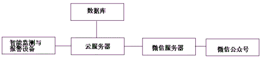
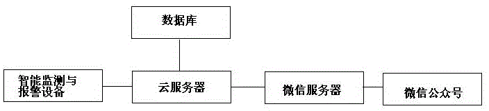
图1是本发明一种智能监测与报警系统的结构原理图;Fig. 1 is a structural principle diagram of an intelligent monitoring and alarm system of the present invention;
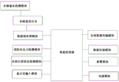
图2是本发明智能监测与报警设备的结构原理图;Fig. 2 is the structural principle diagram of intelligent monitoring and alarm equipment of the present invention;
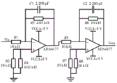
图3是本发明数据预处理模块的电路图;Fig. 3 is the circuit diagram of data preprocessing module of the present invention;
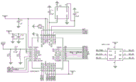
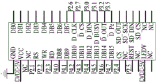
图4是本发明无线数据传输模块的电路图;Fig. 4 is the circuit diagram of wireless data transmission module of the present invention;
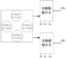
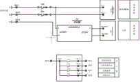
图5是本发明阵列式水浸传感器与多路复用模拟开关示意图;Fig. 5 is a schematic diagram of the array type water immersion sensor and the multiplexing analog switch of the present invention;
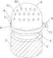
图6是本发明报警模块的整体立体结构示意图;6 is a schematic diagram of the overall three-dimensional structure of the alarm module of the present invention;
图7是本发明整体立体局部剖面结构示意图;Fig. 7 is a schematic diagram of the overall three-dimensional partial cross-sectional structure of the present invention;
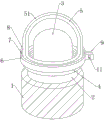
图8为本发明报警器连接件与连接块连接处的爆炸结构示意图;Fig. 8 is a schematic diagram of the exploded structure of the connection between the alarm connector and the connection block of the present invention;
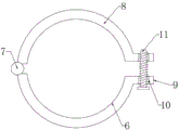
图9为本发明第一卡箍的俯视结构示意图;Fig. 9 is a top structural schematic diagram of the first clip of the present invention;
图10是本发明显示及输入模块的电路图;Fig. 10 is a circuit diagram of the display and input module of the present invention;
图11是本发明智能监测与报警设备接线原理图;Fig. 11 is a schematic diagram of the wiring of the intelligent monitoring and alarm equipment of the present invention;
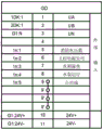
图12是本发明智能监测与报警设备端子图;Fig. 12 is a terminal diagram of the intelligent monitoring and alarm equipment of the present invention;
图13是本发明设备运行逻辑图。Fig. 13 is a logic diagram of the operation of the device of the present invention.
图中标号具体如下:1-报警器底座;2-报警器连接件;3-报警闪灯;4-连接块;5-防护挡板;51-耐高温涂层;52-作用孔;6-第一卡箍;7-活动轴;8-第二卡箍;9-固定块;10-螺纹孔;11-丝杆;。The labels in the figure are as follows: 1- alarm base; 2- alarm connector; 3- alarm flashing light; 4- connecting block; 5- protective baffle; 51- high temperature resistant coating; The first hoop; 7-movable shaft; 8-the second hoop; 9-fixed block; 10-threaded hole; 11-screw mandrel;.
具体实施方式Detailed ways
下面结合附图对本发明的技术方案做进一步的详细说明:Below in conjunction with accompanying drawing, technical scheme of the present invention is described in further detail:
下面将结合本发明实施例中的附图,对本发明实施例中的技术方案进行清楚、完整地描述,显然,所描述的实施例仅仅是本发明一部分实施例,而不是全部的实施例。基于本发明中的实施例,本领域普通技术人员在没有做出创造性劳动前提下所获得的所有其他实施例,都属于本发明保护的范围。The following will clearly and completely describe the technical solutions in the embodiments of the present invention with reference to the accompanying drawings in the embodiments of the present invention. Obviously, the described embodiments are only some, not all, embodiments of the present invention. Based on the embodiments of the present invention, all other embodiments obtained by persons of ordinary skill in the art without making creative efforts belong to the protection scope of the present invention.
本方案,就地监测设计一套消防泵房智能监测与报警设备,安装与消防泵房配电箱旁边;在云端,利用微信小程序,运维人员手机微信关注后,即可收到相关报警信息;In this plan, a set of intelligent monitoring and alarm equipment for fire pump room is designed for local monitoring, and installed next to the distribution box of fire pump room; in the cloud, using the WeChat applet, the operation and maintenance personnel can receive relevant alarms after paying attention to WeChat on their mobile phones information;
该设备由智能控制器、带监视接点的压力表、水浸传感器组成。The device consists of an intelligent controller, a pressure gauge with monitoring contacts, and a water immersion sensor.
将双电源切换箱的备用电源直接接入消防泵房智能监测与报警设备电源端子,监视电压,当备用电源消失时,发出报警信号;Connect the backup power of the dual power switching box directly to the power terminal of the intelligent monitoring and alarm equipment in the fire pump room, monitor the voltage, and send an alarm signal when the backup power disappears;
利用双电源切换箱的主供电源回路接触器辅助接点,当主供电源断电时,接触器的常闭辅助触点闭合,发出报警信号;Using the auxiliary contact of the main power supply circuit contactor of the dual power switching box, when the main power supply is cut off, the normally closed auxiliary contact of the contactor is closed and an alarm signal is sent;
采用带上下限的水压表,当水压低于设定值的时候,接点闭合,发出报警信号;Using a water pressure gauge with upper and lower limits, when the water pressure is lower than the set value, the contact is closed and an alarm signal is issued;
溢水监视,采用水浸传感器,当检测到溢水口有水流出时,相关接点闭合,发出报警信号;Water overflow monitoring, using a water immersion sensor, when it is detected that there is water flowing out of the overflow port, the relevant contacts will be closed and an alarm signal will be issued;
利用水泵控制箱的水泵控制回路的接触器辅助接点,当水泵运行的时候,相关接触器闭合,响应的辅助触点闭合,发出报警信号;Use the contactor auxiliary contact of the water pump control circuit of the water pump control box, when the water pump is running, the relevant contactor is closed, the corresponding auxiliary contact is closed, and an alarm signal is sent;
原理说明:Principle description:
备用电源接入智能控制器,停电后,由智能控制器判断并发出报警;The backup power supply is connected to the intelligent controller. After a power failure, the intelligent controller judges and sends out an alarm;
水箱溢水监视、消防水压力监视、水泵运行监视、主供电源监视,采用相关接点闭合接入智能控制器,由智能控制器判断和发出报警信号;Water tank overflow monitoring, fire water pressure monitoring, water pump operation monitoring, main power supply monitoring, the relevant contact closure is connected to the intelligent controller, and the intelligent controller judges and sends out an alarm signal;
报警信号通过云平台服务推送报警信息到相关管理人员的手机微信上;The alarm signal pushes the alarm information to the mobile WeChat of the relevant management personnel through the cloud platform service;
在手机上的客户端,通过管理功能,可以对报警名称、报警事件间隔、报警机制、推送人员进行设置。On the client side of the mobile phone, through the management function, you can set the alarm name, alarm event interval, alarm mechanism, and push personnel.
具体实施例如下:Specific examples are as follows:
一种智能监测与报警系统,安装在消防泵房配电箱旁,如图1所示,包含智能监测与报警设备、微信服务器、云服务器、数据库和微信公众号,所述智能监测与报警设备与云服务器连接,所述微信服务器与云服务器连接,所述微信服务器和微信公众号连接,所述数据库与云服务器连接;An intelligent monitoring and alarm system is installed next to the distribution box of the fire pump room, as shown in Figure 1, comprising intelligent monitoring and alarm equipment, WeChat server, cloud server, database and WeChat public account, the intelligent monitoring and alarm equipment Connect with the cloud server, the WeChat server is connected with the cloud server, the WeChat server is connected with the WeChat public account, and the database is connected with the cloud server;
相关管理人员首先需要接入网络并且关注公众号,在手机上的客户端,通过管理功能,可以对报警名称、报警事件间隔、报警机制、推送人员进行设置,之后通过密钥绑定消防泵房智能监测与报警设备,就可以在公众号中发送文本、语音消息,或者点击公众号中的菜单实现以下功能:水箱溢水监视、消防水压力监视、水泵运行监视、主供电源监视,采用相关接点闭合接入智能控制器,由智能控制器判断和发出报警信号,报警信号通过云平台服务推送报警信息到相关管理人员的手机微信上,利用微信小程序,运维人员手机微信关注后,即可收到相关报警信。Relevant management personnel first need to access the network and pay attention to the official account. On the client terminal on the mobile phone, through the management function, you can set the alarm name, alarm event interval, alarm mechanism, and push personnel, and then bind the fire pump room through the key Intelligent monitoring and alarm equipment, you can send text and voice messages in the official account, or click the menu in the official account to realize the following functions: water tank overflow monitoring, fire water pressure monitoring, water pump operation monitoring, main power supply monitoring, using relevant contacts Closed access to the intelligent controller, the intelligent controller judges and sends out an alarm signal, and the alarm signal pushes the alarm information to the mobile phone WeChat of the relevant management personnel through the cloud platform service. Using the WeChat applet, the operation and maintenance personnel can pay attention to the mobile phone WeChat. Receipt of relevant alarm letter.
微信服务器定义了公众号菜单,并且把微信客户端发送的消息以可扩展标记语言(Extensible Markup Language,XML)形式的数据发送到阿里云服务器;阿里云服务器根据指令更新数据库,同时接收开发板上传的传感器数据,将数据存入数据库。The WeChat server defines the official account menu, and sends the message sent by the WeChat client to the Alibaba Cloud server in the form of Extensible Markup Language (XML); the Alibaba Cloud server updates the database according to the instructions, and at the same time receives the development board upload sensor data and store the data in the database.
当微信公众号请求数据时,阿里云服务器将响应消息打包成XML数据,并通过微信服务器转发到微信客户端;当开发板请求数据时,阿里云服务器将请求的数据通过HTTP协议响应给开发板。When the WeChat public account requests data, the Alibaba Cloud server packages the response message into XML data and forwards it to the WeChat client through the WeChat server; when the development board requests data, the Alibaba Cloud server responds to the development board with the requested data through the HTTP protocol .
本发明将安装与消防泵房配电箱旁边,将微信公众号和智能控制器相结合,使用云服务器存储数据,通过智能报警装备,使消防泵房从无人值守转变为24小时自动值守,极大地提升了泵房的管控效率,做到全面感知消防泵房的健康与运行状态,在云端,利用微信小程序,运维人员手机微信关注后,即可收到相关报警信息。The invention will be installed next to the distribution box of the fire pump room, combine the WeChat official account and the intelligent controller, use the cloud server to store data, and use the intelligent alarm equipment to change the fire pump room from unattended to 24-hour automatic duty, The management and control efficiency of the pump room has been greatly improved, and the health and operation status of the fire pump room can be fully perceived. In the cloud, using the WeChat applet, the operation and maintenance personnel can receive relevant alarm information after paying attention to WeChat on their mobile phones.
如图2所示,所述智能监测与报警设备包含水箱溢水检测模块、消防水压力检测模块、水泵运营状态检测模块、多路复用开关、数据预处理模块、智能控制器、显示及输入模块、无线数据传输模块、数据存储模块、报警模块和电源模块;As shown in Figure 2, the intelligent monitoring and alarm equipment includes a water tank overflow detection module, a fire water pressure detection module, a water pump operation status detection module, a multiplexing switch, a data preprocessing module, an intelligent controller, a display and an input module , wireless data transmission module, data storage module, alarm module and power supply module;
所述水箱溢水检测模块、水泵运营状态检测模块分别与智能控制器连接,所述消防水压The water tank overflow detection module and the water pump operation state detection module are respectively connected to the intelligent controller, and the fire water pressure
力检测模块依次经过多路复用开关、数据预处理模块连接智能控制器,所述无线数据传输模块、数据存储模块、显示及输入模块、报警模块和分别与智能控制器连接,所述电源模块分别与水箱溢水检测模块、消防水压力检测模块、多路复用开关、数据预处理模块、智能控制器、显示及输入模块、无线数据传输模块和报警模块连接。The force detection module is connected to the intelligent controller through the multiplexing switch and the data preprocessing module in turn, the wireless data transmission module, the data storage module, the display and input module, the alarm module are respectively connected to the intelligent controller, and the power supply module It is respectively connected with a water tank overflow detection module, a fire water pressure detection module, a multiplexing switch, a data preprocessing module, an intelligent controller, a display and input module, a wireless data transmission module and an alarm module.
其中,水箱溢水检测模块,采用由多个水浸传感器构成的水浸传感器阵列,用于检测溢水口是否有水流出;采用分布阵列式多点平均测量方式,有效地消除了由于传感器个体本身的缺陷带来的测量误差和减少了由于传感器芯片蠕变而产生的随机误差或重复性误差,显著减少了年漂的影响。Among them, the water tank overflow detection module adopts a water immersion sensor array composed of a plurality of water immersion sensors to detect whether there is water flowing out of the overflow port; it adopts a distributed array multi-point average measurement method, which effectively eliminates the The measurement error caused by the defect and the random error or repeatability error caused by the creep of the sensor chip are reduced, and the influence of the annual drift is significantly reduced.
消防水压力检测模块,采用带上下限的水压表,用于采集消防水压参数,进而上传至智能控制器;The fire water pressure detection module adopts a water pressure gauge with upper and lower limits to collect fire water pressure parameters and upload them to the intelligent controller;
水泵运营状态检测模块,用于采集水泵电压参数,进而上传至智能控制器;The water pump operation status detection module is used to collect the water pump voltage parameters and upload them to the intelligent controller;
多路复用开关,用于通过多路复用模拟开关选择分时输出给后续的数据预处理模块,本发明的阵列式水浸传感器与多路复用模拟开关示意图如图5所示;The multiplexing switch is used to select the time-sharing output to the subsequent data preprocessing module through the multiplexing analog switch. The schematic diagram of the array type water immersion sensor and the multiplexing analog switch of the present invention is shown in Figure 5;
数据预处理模块,用于将水浸传感器采集的水参数由多路复用模拟开关选择输出给信号处理电路后再输入到智能控制器,由智能控制器判断和发出报警信号;The data preprocessing module is used to select and output the water parameters collected by the water immersion sensor to the signal processing circuit through the multiplexing analog switch, and then input it to the intelligent controller, and the intelligent controller judges and sends out an alarm signal;
无线数据传输模块,用于将智能控制器判断和发出报警信号上传至阿里云服务器,The wireless data transmission module is used to upload the judgment and alarm signal of the intelligent controller to the Alibaba Cloud server,
微信服务器,用于通过微信公众号推送报警信息到相关管理人员的手机微信上;WeChat server, which is used to push the alarm information to the mobile phone WeChat of the relevant management personnel through the WeChat public account;
微信公众号,在手机上的客户端,通过管理功能,可以对报警名称、报警事件间隔、报警机制、推送人员进行设置;WeChat official account, the client on the mobile phone, through the management function, you can set the alarm name, alarm event interval, alarm mechanism, and push personnel;
显示及输入模块,用于设定水浸传感器和水压表参数阈值;The display and input module are used to set the parameter thresholds of the water sensor and the water pressure gauge;
报警模块,用于根据预先设定的阈值发出警报;an alarm module, configured to issue an alarm according to a preset threshold;
数据存储模块,用于存储水浸传感器、水压表采集的参数和水泵运营状态检测参数;The data storage module is used to store the parameters collected by the water immersion sensor and the water pressure gauge and the detection parameters of the water pump operation status;
电源模块,用于提供水箱溢水检测模块、消防水压力检测模块、水泵运营状态检测模块、多路复用开关、数据预处理模块、智能控制器、无线数据传输模块、报警模块所需电能。The power supply module is used to provide the power required by the water tank overflow detection module, fire water pressure detection module, water pump operation status detection module, multiplexing switch, data preprocessing module, intelligent controller, wireless data transmission module, and alarm module.
如图3所示,所述数据预处理模块包含第一电阻R1、第二电阻R2、第三电阻R3、第四电阻R4、第五电阻R5、第六电阻R6、第七电阻R7、第八电阻R8、第一电容C1、第二电容C2、第一运算放大器U1、第二运算放大器U2、电压输入VIN端和电压输出VOUT端,电压输入VIN端连接第一电阻R1的一端,第一电阻R1的另一端分别连接第一运算放大器U1的负极输入端、第二电阻R2的一端和第一电容C1的一端,第一电容C1的另一端分别连接第二电阻R2的另一端、第一运算放大器U1的输出端和第五电阻R5的一端,第五电阻R5的另一端分别连接第二电容C2的一端、第六电阻R6的一端和第二运算放大器U2的负极输入端,第二电容C2的另一端分别连接第六电阻R6的另一端、第二运算放大器U2的输出端和电压输出VOUT端,第二运算放大器U2的正极输入端分别连接第七电阻R7的一端、第八电阻R8的一端,第七电阻R7的另一端和第八电阻R8的另一端连接并接地,第一运算放大器U1的正极输入端分别连接第三电阻R3的一端和第四电阻R4的一端,第三电阻R3的另一端和第四电阻R4的另一端连接并接地。As shown in Figure 3, the data preprocessing module includes a first resistor R1, a second resistor R2, a third resistor R3, a fourth resistor R4, a fifth resistor R5, a sixth resistor R6, a seventh resistor R7, an eighth resistor Resistor R8, first capacitor C1, second capacitor C2, first operational amplifier U1, second operational amplifier U2, voltage input VIN terminal and voltage output VOUT terminal, the voltage input VIN terminal is connected to one end of the first resistor R1, the first resistor The other end of R1 is respectively connected to the negative input terminal of the first operational amplifier U1, one end of the second resistor R2 and one end of the first capacitor C1, and the other end of the first capacitor C1 is respectively connected to the other end of the second resistor R2, the first operational The output end of the amplifier U1 and one end of the fifth resistor R5, the other end of the fifth resistor R5 are respectively connected to one end of the second capacitor C2, one end of the sixth resistor R6 and the negative input end of the second operational amplifier U2, the second capacitor C2 The other terminal of the second operational amplifier U2 is respectively connected to the other terminal of the sixth resistor R6, the output terminal of the second operational amplifier U2 and the voltage output VOUT terminal, and the positive input terminal of the second operational amplifier U2 is respectively connected to one terminal of the seventh resistor R7 and the terminal of the eighth resistor R8. One end, the other end of the seventh resistor R7 and the other end of the eighth resistor R8 are connected and grounded, the positive input end of the first operational amplifier U1 is respectively connected to one end of the third resistor R3 and one end of the fourth resistor R4, and the third resistor R3 The other end of the resistor R4 is connected to the other end of the fourth resistor R4 and grounded.
如图4所示,所述无线数据传输模块包含天线ANT1、电容C11、电容C12、电容C13、电容C14、电容C15、电容C16、电阻R221、电阻R22、电感L11、电感L12、芯片U1、芯片U2、芯片U3、VDD端,其中,天线ANT1分别连接电感L11的一端、电容C16的一端,电感L11的另一端接地,电容C16的另一端分别连接电感L12的一端和芯片U1的引脚2,电感L12的另一端接地,芯片U1的引脚3和芯片U1的引脚4分别连接电容C14的一端、电容C15的一端和VDD端,电容C14的另一端、电容C15的另一端分别接地,芯片U1的引脚1分别连接电容C13的一端、VDD端、芯片U1的引脚30和芯片U1的引脚29,电容C13的另一端接地,芯片U1的引脚31连接电阻R221的一端,电阻R221的另一端接地,芯片U1的引脚28分别连接电容C11的一端和芯片U2的引脚1,芯片U2的引脚2接地,电容C11的另一端接地,芯片U2的引脚4接地,芯片U2的引脚3分别连接电容C12的一端和芯片U1的引脚27,电容C12的另一端接地,芯片U1的引脚18连接芯片U3的引脚7,芯片U1的引脚19连接芯片U3的引脚3,芯片U1的引脚20连接芯片U3的引脚1,芯片U1的引脚21经过电阻R22连接芯片U3的引脚6,芯片U1的引脚22连接芯片U3的引脚2,芯片U1的引脚23连接芯片U3的引脚5,芯片U1的引脚17分别连接芯片U1的引脚11和VDD端。As shown in Figure 4, the wireless data transmission module includes antenna ANT1, capacitor C11, capacitor C12, capacitor C13, capacitor C14, capacitor C15, capacitor C16, resistor R221, resistor R22, inductor L11, inductor L12, chip U1, chip U2, chip U3, and VDD terminals, wherein the antenna ANT1 is connected to one end of the inductor L11 and one end of the capacitor C16, the other end of the inductor L11 is grounded, and the other end of the capacitor C16 is respectively connected to one end of the inductor L12 and pin 2 of the chip U1, The other end of the inductor L12 is grounded, the pin 3 of the chip U1 and the pin 4 of the chip U1 are respectively connected to one end of the capacitor C14, one end of the capacitor C15, and the VDD end, and the other end of the capacitor C14 and the other end of the capacitor C15 are respectively grounded, and the chip Pin 1 of U1 is connected to one end of capacitor C13, VDD, pin 30 of chip U1, and pin 29 of chip U1, the other end of capacitor C13 is grounded, pin 31 of chip U1 is connected to one end of resistor R221, and resistor R221 The other end of the capacitor C11 is grounded, the pin 28 of the chip U1 is respectively connected to one end of the capacitor C11 and the pin 1 of the chip U2, the pin 2 of the chip U2 is grounded, the other end of the capacitor C11 is grounded, the pin 4 of the chip U2 is grounded, and the chip U2 The pin 3 of the chip U1 is connected to one end of the capacitor C12 and the pin 27 of the chip U1, the other end of the capacitor C12 is grounded, the pin 18 of the chip U1 is connected to the pin 7 of the chip U3, and the pin 19 of the chip U1 is connected to the pin of the chip U3.
所述智能控制器采用芯片型号为SPCE061A的微处理器。经过实际测试,该系统具有较The intelligent controller adopts a microprocessor whose chip model is SPCE061A. After actual testing, the system has a relatively
强的网络通信能力、高实时性、通信快速可靠的特点,具有很高的实用价值。Strong network communication capability, high real-time performance, fast and reliable communication features, have high practical value.
SPCE061A微处理器是凌阳科技公司所生产的16位μ'nSPTM微处理器,内部采用总线结构。主要参数有:工作电压(CPU)VDD为2.4~3.6 V,(I/O)VDDH为2.4~5.5 V;时钟:0.32~49.152 MHz;内置2 KBSRAM和32 KB FLASH;2个16位可编程定时器/计数器(可自动预置初始计数值);2个10位DAC(数/模转换)输出通道;32位I/O位通用可编程输入/输出端口;14个中断源可来自定时器A/B时基,2个外部时钟源输入,键唤醒;中断系统支持10个中断向量及10余个中断源,具有低电压复位(LVR)功能和低电压监测(LVD)功能,内置在线仿真电路ICE接口,具有保密能力,具有Watch Dog功能,μ'nSPTM的指令系统提供具有较高运算速度的16位×16位乘法运算指令和内积运算指令,为其应用增添了DSP功能。The SPCE061A microprocessor is a 16-bit μ'nSPTM microprocessor produced by Sunplus Technology Co., Ltd., which uses a bus structure internally. The main parameters are: working voltage (CPU) VDD is 2.4-3.6 V, (I/O) VDDH is 2.4-5.5 V; clock: 0.32-49.152 MHz; built-in 2 KBSRAM and 32 KB FLASH; 2 16-bit programmable timers/counters (can automatically preset the initial count value); 2 10-bit DAC (digital/analog conversion) output channels; 32-bit I/O bit general-purpose programmable input/ Output port; 14 interrupt sources can come from timer A/B time base, 2 external clock source input, key wake-up; interrupt system supports 10 interrupt vectors and more than 10 interrupt sources, with low voltage reset (LVR) function and Low voltage monitoring (LVD) function, built-in online simulation circuit ICE interface, with confidentiality ability, with Watch Dog function, μ'nSPTM instruction system provides 16-bit × 16-bit multiplication operation instruction and inner product operation instruction with high operation speed , adding DSP functionality to its application.
SPCE061A具有很高的计算速度,这对于实时操作系统是极为重要的。对于SPCE061A,传统的微处理器硬件和软件的开发已被简化,不再需要在线仿真。其SPCE061A大容量FLASH及SRAM,内建以太网接口,可直接通过网络实现监控;具备UART接口,可使各种串行设备快速进行网络连接。SPCE061A微处理器的软件开发平台ICE集编程、编译、链接、调试、下载于一体,并有完善的TCP/IP协议栈,支持全功能UART通信,配备各种I/O驱动函数库。SPCE061A has very high computing speed, which is extremely important for real-time operating systems. For SPCE061A, the development of traditional microprocessor hardware and software has been simplified, and online emulation is no longer required. Its SPCE061A has large-capacity FLASH and SRAM, and has a built-in Ethernet interface, which can be directly monitored through the network; it has a UART interface, which can quickly connect various serial devices to the network. The software development platform ICE of SPCE061A microprocessor integrates programming, compiling, linking, debugging and downloading, and has a perfect TCP/IP protocol stack, supports full-featured UART communication, and is equipped with various I/O driver function libraries.
如图6-图9所示,所述报警模块包括报警器底座1,所述报警器底座1顶部固定连接有报警器连接件2,所述报警器连接件2内壁固定连接有报警闪灯3,所述报警闪灯3外壁活动套接有防护挡板5,所述防护挡板5底部固定连接有连接块4,所述连接块4内壁与报警器连接件2外壁螺纹连接,所述连接块4外壁设置有第一卡箍6,所述第一卡箍6外壁一侧设置有活动轴7,所述活动轴7外壁远离第一卡箍6的一侧设置有第二卡箍8,所述第二卡箍8与第一卡箍6通过活动轴7相铰接,所述第二卡箍8与第一卡箍6外壁一侧均固定连接有固定块9,所述固定块9内部贯穿有螺纹孔10,所述螺纹孔10内部螺纹连接有丝杆11,所述第二卡箍8与第一卡箍6内壁之间与连接块4相匹配。As shown in Figures 6-9, the alarm module includes an alarm base 1, an alarm connector 2 is fixedly connected to the top of the alarm base 1, and an alarm flashing light 3 is fixedly connected to the inner wall of the alarm connector 2 , the outer wall of the alarm flashing light 3 is movably socketed with a protective baffle 5, the bottom of the protective baffle 5 is fixedly connected with a connecting block 4, the inner wall of the connecting block 4 is threaded with the outer wall of the alarm connector 2, and the connecting The outer wall of the block 4 is provided with a first clamp 6, and a movable shaft 7 is provided on one side of the outer wall of the first clamp 6, and a second clamp 8 is provided on a side of the outer wall of the movable shaft 7 away from the first clamp 6, The second clamp 8 and the first clamp 6 are hinged through the movable shaft 7, and the second clamp 8 and the first clamp 6 are fixedly connected with a fixed block 9 on one side of the outer wall, and the inside of the fixed block 9 A threaded hole 10 runs through, and a threaded rod 11 is threaded inside the threaded hole 10 , and the inner wall of the second clamp 8 and the first clamp 6 is matched with the connection block 4 .
如图6和图7所示,所述防护挡板5外壁与内壁均固定连接有耐高温涂层51;所述耐高温涂层51的耐温为250摄氏度。所述防护挡板5内部贯穿有作用孔52,所述作用孔52的数量设置有多个,多个所述作用孔52均与报警闪灯3相对应。As shown in Figure 6 and Figure 7, the outer wall and the inner wall of the
所述数据存储模块采用ST公司的S25FL128P Flash存储器进行实时存储,该芯片存储容量为128 Mbit,通过SPI接口与外部控制器建立通信,接口的时钟频率最大可达到104 MHzThe data storage module adopts ST's S25FL128P Flash memory for real-time storage. The chip has a storage capacity of 128 Mbit, and establishes communication with an external controller through an SPI interface. The maximum clock frequency of the interface can reach 104 MHz
如图10所示,所述显示及输入模块为低功耗2.4寸ALIENTEK TFTLCD。由TFT触摸液晶屏构成显示控制电路,电缆接头温度参数可以通过液晶屏实时显示出来,对于报警阈值,用户也可以根据自己的要求通过触摸屏输入设置。As shown in Figure 10, the display and input module is a low-power 2.4-inch ALIENTEK TFTLCD. The display control circuit is composed of a TFT touch LCD screen. The temperature parameters of the cable joint can be displayed in real time through the LCD screen. For the alarm threshold, the user can also input and set it through the touch screen according to his own requirements.
所述电源模块采用双电源切换箱。图11和图12所示,接线说明:The power supply module adopts a dual power supply switching box. As shown in Figure 11 and Figure 12, wiring instructions:
电源接消防电源箱辅供电源的A相、B相,N相直接接入;A相接GD:1,B相接GD:2,N接GD:3;The power supply is directly connected to the A phase, B phase and N phase of the auxiliary power supply of the fire power box; the A phase is connected to GD: 1, the B phase is connected to GD: 2, and the N is connected to GD: 3;
水浸探测器,红线(24V正)接GD:10,黑线(24V负)接GD:11,绿线接GD:7,蓝线接GD:9',水浸传感器放在水箱溢水管出口处,线要延长;For the water immersion detector, the red wire (24V positive) is connected to GD:10, the black wire (24V negative) is connected to GD:11, the green wire is connected to GD:7, the blue wire is connected to GD:9', and the water sensor is placed at the outlet of the overflow pipe of the water tank , the line should be extended;
水压传感器,压力表的接线柱1和2分别接GD:5和GD:9,实现水压低的时候报警;The water pressure sensor, the
主供电源的监视,从主供电源的接触器常闭点取,将常闭点两根线接入GD:6和GD:9'端子(平时确保主供电源接触器处于吸合状态);The monitoring of the main power supply is taken from the normally closed point of the contactor of the main power supply, and the two wires of the normally closed point are connected to the GD:6 and GD:9' terminals (usually ensure that the main power supply contactor is in the suction state);
水泵运行监视,将两个水泵控制器接触器的常开点并起来,将两根线接入GD:8和GD:9'端子。For water pump operation monitoring, connect the normally open points of the two water pump controller contactors together, and connect the two wires to the GD:8 and GD:9' terminals.
设备运行逻辑图,如图13所示,The logic diagram of equipment operation is shown in Figure 13.
步骤1,设备自检;
步骤2,数据采集;
步骤3,数据计算;
步骤4,若主供电压高于上限或低于下限,则主供电压异常报警,反之则进行步骤5;
步骤5,若辅助电压高于上限或低于下限,则辅助电压异常报警,反之则进行步骤6;
步骤6,若消防水管压力低于定值,则消防水压力异常报警,反之则进行步骤7;
步骤7,若消防水箱溢水口出水,则消防水箱溢水报警,反之则进行步骤8;
步骤8,若消防水泵运行,则消防水泵运行提示,反之则进行步骤1。
本技术领域技术人员可以理解的是,除非另外定义,这里使用的所有术语(包括技术术语和科学术语)具有与本发明所属领域中的普通技术人员的一般理解相同的意义。还应该理解的是,诸如通用字典中定义的那些术语应该被理解为具有与现有技术的上下文中的意义一致的意义,并且除非像这里一样定义,不会用理想化或过于正式的含义来解释。Those skilled in the art can understand that, unless otherwise defined, all terms (including technical terms and scientific terms) used herein have the same meaning as commonly understood by those of ordinary skill in the art to which this invention belongs. It should also be understood that terms such as those defined in commonly used dictionaries should be understood to have a meaning consistent with the meaning in the context of the prior art, and unless defined as herein, are not to be interpreted in an idealized or overly formal sense explain.
以上实施例仅为说明本发明的技术思想,不能以此限定本发明的保护范围,凡是按照本发明提出的技术思想,在技术方案基础上所做的任何改动,均落入本发明保护范围之内。上面对本发明的实施方式作了详细说明,但是本发明并不限于上述实施方式,在本领域普通技术人员所具备的知识范围内,还可以在不脱离本发明宗旨的前提下做出各种变化。The above embodiments are only to illustrate the technical ideas of the present invention, and cannot limit the scope of protection of the present invention with this. Any changes made on the basis of technical solutions according to the technical ideas proposed in the present invention all fall within the scope of protection of the present invention. Inside. The embodiments of the present invention have been described in detail above, but the present invention is not limited to the above embodiments, and various changes can be made without departing from the gist of the present invention within the scope of knowledge of those skilled in the art. .
最后应说明的是:以上各实施例仅用以说明本发明的技术方案,而非对其限制;尽管参照前述各实施例对本发明进行了详细的说明,本领域的普通技术人员应当理解:其依然可以对前述各实施例所记载的技术方案进行修改,或者对其中部分或者全部技术特征进行等同替换;而这些修改或者替换,并不使相应技术方案的本质脱离本发明各实施例技术方案的范围。Finally, it should be noted that: the above embodiments are only used to illustrate the technical solutions of the present invention, rather than limiting them; although the present invention has been described in detail with reference to the foregoing embodiments, those of ordinary skill in the art should understand that: It is still possible to modify the technical solutions described in the foregoing embodiments, or perform equivalent replacements for some or all of the technical features; and these modifications or replacements do not make the essence of the corresponding technical solutions deviate from the technical solutions of the various embodiments of the present invention. scope.
Claims (10)
Priority Applications (1)
| Application Number | Priority Date | Filing Date | Title |
|---|---|---|---|
| CN202310480953.1A CN116434500A (en) | 2023-04-28 | 2023-04-28 | An Intelligent Monitoring and Alarming System |
Applications Claiming Priority (1)
| Application Number | Priority Date | Filing Date | Title |
|---|---|---|---|
| CN202310480953.1A CN116434500A (en) | 2023-04-28 | 2023-04-28 | An Intelligent Monitoring and Alarming System |
Publications (1)
| Publication Number | Publication Date |
|---|---|
| CN116434500A true CN116434500A (en) | 2023-07-14 |
Family
ID=87090767
Family Applications (1)
| Application Number | Title | Priority Date | Filing Date |
|---|---|---|---|
| CN202310480953.1A Pending CN116434500A (en) | 2023-04-28 | 2023-04-28 | An Intelligent Monitoring and Alarming System |
Country Status (1)
| Country | Link |
|---|---|
| CN (1) | CN116434500A (en) |
Cited By (1)
| Publication number | Priority date | Publication date | Assignee | Title |
|---|---|---|---|---|
| CN117152907A (en) * | 2023-08-29 | 2023-12-01 | 中安建设安装集团有限公司 | Fire control and safety assurance system integrated with indoor intelligent fire protection products |
Citations (5)
| Publication number | Priority date | Publication date | Assignee | Title |
|---|---|---|---|---|
| US20060109113A1 (en) * | 2004-09-17 | 2006-05-25 | Reyes Tommy D | Computer-enabled, networked, facility emergency notification, management and alarm system |
| CN111273597A (en) * | 2020-01-24 | 2020-06-12 | 西南石油大学 | Centralized monitoring and inspection system for firefighting facilities |
| CN211236599U (en) * | 2020-03-04 | 2020-08-11 | 李敏 | CC3200 and wechat public account-based cloud home interaction system |
| CN211787383U (en) * | 2020-09-19 | 2020-10-27 | 深圳市海纳龙科技有限公司 | High temperature resistant fire alarm device |
| CN114457873A (en) * | 2022-03-13 | 2022-05-10 | 湖北泉洁二次供水工程有限公司 | Intelligent data monitoring system for secondary water supply |
-
2023
- 2023-04-28 CN CN202310480953.1A patent/CN116434500A/en active Pending
Patent Citations (5)
| Publication number | Priority date | Publication date | Assignee | Title |
|---|---|---|---|---|
| US20060109113A1 (en) * | 2004-09-17 | 2006-05-25 | Reyes Tommy D | Computer-enabled, networked, facility emergency notification, management and alarm system |
| CN111273597A (en) * | 2020-01-24 | 2020-06-12 | 西南石油大学 | Centralized monitoring and inspection system for firefighting facilities |
| CN211236599U (en) * | 2020-03-04 | 2020-08-11 | 李敏 | CC3200 and wechat public account-based cloud home interaction system |
| CN211787383U (en) * | 2020-09-19 | 2020-10-27 | 深圳市海纳龙科技有限公司 | High temperature resistant fire alarm device |
| CN114457873A (en) * | 2022-03-13 | 2022-05-10 | 湖北泉洁二次供水工程有限公司 | Intelligent data monitoring system for secondary water supply |
Cited By (1)
| Publication number | Priority date | Publication date | Assignee | Title |
|---|---|---|---|---|
| CN117152907A (en) * | 2023-08-29 | 2023-12-01 | 中安建设安装集团有限公司 | Fire control and safety assurance system integrated with indoor intelligent fire protection products |
Similar Documents
| Publication | Publication Date | Title |
|---|---|---|
| CN102974064B (en) | Fire-extinguishing agent gas pressure network monitoring system of gas fire-extinguishing system bottle unit | |
| CN103310579B (en) | Electric power fire composite detecting device based on ZigBee radio communication | |
| CN204423091U (en) | A kind of workover platform remote environment supervisory system | |
| CN103196495A (en) | Vacuum section switch fault pre-warning system for urban and rural power supply line | |
| CN207731442U (en) | A kind of distributed intelligence electric fire monitoring system | |
| CN202648702U (en) | SF6 gas on-line monitoring unit | |
| CN204243909U (en) | A kind of SF 6primary cut-out Leakage Gas remote monitoring device | |
| CN203253094U (en) | Intelligent firefighting remote monitoring and automatic inspection system | |
| CN201796453U (en) | Bus Type Electrical Fire Monitoring System | |
| CN201221964Y (en) | Resident water use abnormity monitoring system apparatus | |
| CN210572215U (en) | Online monitoring and management system for sulfur hexafluoride gas density of converter station | |
| CN203630924U (en) | Outdoor electric power equipment condensation alarm device | |
| CN207924405U (en) | a kind of intelligent water pump controller gateway based on internet of things | |
| CN112147965A (en) | Vaporized hydrogen peroxide on-line monitoring and process control system and method thereof | |
| CN106910312A (en) | A kind of intelligent repository remote data monitoring warning system | |
| CN118384467A (en) | Intelligent Internet of things monitoring system and method for expressway tunnel fire-fighting equipment | |
| CN209562577U (en) | A kind of fire-alarm gateway | |
| CN206601602U (en) | A kind of dynamic environment data monitoring system | |
| CN206820548U (en) | Intelligently transport checking device in a kind of power distribution station | |
| CN203055081U (en) | Residual current-type electrical fire monitoring detector | |
| CN210350858U (en) | Intelligent substation monitoring system based on smart phone | |
| CN111273597A (en) | Centralized monitoring and inspection system for firefighting facilities | |
| CN204966989U (en) | Take switch board safety monitoring device of temperature detection | |
| CN202352017U (en) | Independent early warning electrical fire monitoring detector | |
| CN207676161U (en) | A kind of touch screen display gas warning system |
Legal Events
| Date | Code | Title | Description |
|---|---|---|---|
| PB01 | Publication | ||
| PB01 | Publication | ||
| SE01 | Entry into force of request for substantive examination | ||
| SE01 | Entry into force of request for substantive examination | ||
| RJ01 | Rejection of invention patent application after publication |
Application publication date: 20230714 |
|
| RJ01 | Rejection of invention patent application after publication |