CN116429609A - Material hardness detection system and detection process for building construction - Google Patents
Material hardness detection system and detection process for building construction Download PDFInfo
- Publication number
- CN116429609A CN116429609A CN202310392301.2A CN202310392301A CN116429609A CN 116429609 A CN116429609 A CN 116429609A CN 202310392301 A CN202310392301 A CN 202310392301A CN 116429609 A CN116429609 A CN 116429609A
- Authority
- CN
- China
- Prior art keywords
- pushing
- anchoring
- hardness
- anchor
- shell
- Prior art date
- Legal status (The legal status is an assumption and is not a legal conclusion. Google has not performed a legal analysis and makes no representation as to the accuracy of the status listed.)
- Pending
Links
- 238000001514 detection method Methods 0.000 title claims abstract description 41
- 239000000463 material Substances 0.000 title claims abstract description 21
- 238000000034 method Methods 0.000 title claims abstract description 12
- 238000009435 building construction Methods 0.000 title abstract description 7
- 238000004873 anchoring Methods 0.000 claims abstract description 85
- 230000005540 biological transmission Effects 0.000 claims description 24
- 238000010276 construction Methods 0.000 claims description 15
- 235000014676 Phragmites communis Nutrition 0.000 claims description 11
- 238000004080 punching Methods 0.000 claims description 5
- 238000009434 installation Methods 0.000 claims description 4
- 230000035939 shock Effects 0.000 claims description 4
- 230000000087 stabilizing effect Effects 0.000 claims description 4
- 238000007542 hardness measurement Methods 0.000 claims 6
- 238000010521 absorption reaction Methods 0.000 claims 1
- 230000001788 irregular Effects 0.000 abstract description 7
- 230000033001 locomotion Effects 0.000 description 22
- 239000004570 mortar (masonry) Substances 0.000 description 4
- 230000008878 coupling Effects 0.000 description 3
- 238000010168 coupling process Methods 0.000 description 3
- 238000005859 coupling reaction Methods 0.000 description 3
- 238000007711 solidification Methods 0.000 description 3
- 230000008023 solidification Effects 0.000 description 3
- 239000011083 cement mortar Substances 0.000 description 2
- 230000009286 beneficial effect Effects 0.000 description 1
- 238000013016 damping Methods 0.000 description 1
- 238000010586 diagram Methods 0.000 description 1
- 230000000694 effects Effects 0.000 description 1
- 238000001125 extrusion Methods 0.000 description 1
- 239000011521 glass Substances 0.000 description 1
- 230000009545 invasion Effects 0.000 description 1
- 230000035515 penetration Effects 0.000 description 1
- 238000000926 separation method Methods 0.000 description 1
- 239000007787 solid Substances 0.000 description 1
Images




Classifications
-
- G—PHYSICS
- G01—MEASURING; TESTING
- G01N—INVESTIGATING OR ANALYSING MATERIALS BY DETERMINING THEIR CHEMICAL OR PHYSICAL PROPERTIES
- G01N3/00—Investigating strength properties of solid materials by application of mechanical stress
- G01N3/40—Investigating hardness or rebound hardness
-
- G—PHYSICS
- G01—MEASURING; TESTING
- G01N—INVESTIGATING OR ANALYSING MATERIALS BY DETERMINING THEIR CHEMICAL OR PHYSICAL PROPERTIES
- G01N3/00—Investigating strength properties of solid materials by application of mechanical stress
- G01N3/02—Details
-
- G—PHYSICS
- G01—MEASURING; TESTING
- G01N—INVESTIGATING OR ANALYSING MATERIALS BY DETERMINING THEIR CHEMICAL OR PHYSICAL PROPERTIES
- G01N3/00—Investigating strength properties of solid materials by application of mechanical stress
- G01N3/02—Details
- G01N3/04—Chucks
-
- G—PHYSICS
- G01—MEASURING; TESTING
- G01N—INVESTIGATING OR ANALYSING MATERIALS BY DETERMINING THEIR CHEMICAL OR PHYSICAL PROPERTIES
- G01N2203/00—Investigating strength properties of solid materials by application of mechanical stress
- G01N2203/0058—Kind of property studied
- G01N2203/0076—Hardness, compressibility or resistance to crushing
-
- Y—GENERAL TAGGING OF NEW TECHNOLOGICAL DEVELOPMENTS; GENERAL TAGGING OF CROSS-SECTIONAL TECHNOLOGIES SPANNING OVER SEVERAL SECTIONS OF THE IPC; TECHNICAL SUBJECTS COVERED BY FORMER USPC CROSS-REFERENCE ART COLLECTIONS [XRACs] AND DIGESTS
- Y02—TECHNOLOGIES OR APPLICATIONS FOR MITIGATION OR ADAPTATION AGAINST CLIMATE CHANGE
- Y02W—CLIMATE CHANGE MITIGATION TECHNOLOGIES RELATED TO WASTEWATER TREATMENT OR WASTE MANAGEMENT
- Y02W30/00—Technologies for solid waste management
- Y02W30/50—Reuse, recycling or recovery technologies
- Y02W30/91—Use of waste materials as fillers for mortars or concrete
Landscapes
- Physics & Mathematics (AREA)
- Health & Medical Sciences (AREA)
- Life Sciences & Earth Sciences (AREA)
- Chemical & Material Sciences (AREA)
- Analytical Chemistry (AREA)
- Biochemistry (AREA)
- General Health & Medical Sciences (AREA)
- General Physics & Mathematics (AREA)
- Immunology (AREA)
- Pathology (AREA)
- Conveying And Assembling Of Building Elements In Situ (AREA)
Abstract
The utility model provides a material hardness detection system for building construction and a detection process, comprising a base mechanism, wherein the top surface of the base mechanism is provided with a shell, one end of the top surface of the shell is embedded with a control panel, one end of the shell is provided with a laser positioning assembly, the inside of the shell and the middle part of the top surface of the base mechanism are provided with a pushing mechanism, one side of the pushing mechanism is provided with a limit rotating mechanism, the upper part of one side of the limit rotating mechanism is provided with a hardness detector, the execution end of the hardness detector is provided with a replaceable feeler lever, and one side of the shell is provided with an anchoring mechanism; aiming the vertical surface to be detected through the laser positioning assembly, wherein the laser aiming can adapt to the irregular vertical surface, and the device is further stabilized by matching with the anchoring mechanism, so that the detection accuracy is ensured; the hardness detection accuracy aiming at the irregular vertical face is greatly improved through the fact that the limiting rotating mechanism is used for detecting the point at the same position for multiple times.
Description
Technical Field
The utility model relates to the technical field of detection of constructional engineering, in particular to a system and a process for detecting hardness of a material for construction.
Background
Hardness is a physical term of art and the ability of a material to locally resist penetration of hard objects into its surface is called hardness. The local resistance of the solid to the invasion of external objects is an index for comparing the softness and hardness of various materials.
In the construction process of the building engineering, the hardness of cement mortar or concrete needs to be detected, and the hardness of the building mortar needs to be detected after solidification because the solidification effect is different under different environments and weather, so that the following construction period is facilitated.
According to the hardness detecting system for the solidification building mortar that patent document of application number CN202220275777.9 provided, including hardness detecting system body and scale, the rotation wheel has been installed to the bottom of hardness detecting system body, the top fixedly connected with connecting block of hardness detecting system body, the movable plate has been installed to the inside of connecting block, the side fixedly connected with fixed block of movable plate. According to the utility model, the hardness detection system body is pushed, so that the three groups of connecting rods are perpendicular to the wall surface and pushed to the connecting blocks, after the rubber blocks are contacted with the solidified building mortar, the extrusion force can be pushed to the movable plate through the connecting rods, the pointer at the bottom end of the movable rod can move on the surface of the graduated scale, the data on the surface of the graduated scale is observed through the glass window, and the state and hardness of the solidified building mortar are obtained through calculation, so that the detection is more convenient and accurate, and the next work is convenient.
But its simple structure is crude, can't adapt to the complex environment of building site, especially to the intensity test of irregular building facade, and above-mentioned patent can't detect it accurately.
Disclosure of Invention
The utility model provides a system and a process for detecting hardness of materials for building construction, aiming at solving the technical problem of how to detect hardness of cement mortar or concrete on irregular building facades, which is proposed in the background art.
In order to achieve the above purpose, the present utility model provides the following technical solutions: the utility model provides a material hardness detecting system for construction, includes base unit, base unit's top surface is equipped with the shell, the top surface one end of shell is inlayed and is equipped with control panel, the one end of shell is equipped with laser positioning component, the inside of shell the top surface middle part of base unit is equipped with advancing mechanism, one side of advancing mechanism is equipped with spacing rotary mechanism, one side upper portion of spacing rotary mechanism is equipped with hardness detector, hardness detector's execution end is equipped with removable feeler lever, one side of shell is equipped with anchoring mechanism.
Further, the base mechanism includes the chassis, the both sides of chassis symmetry respectively are equipped with a plurality of shock attenuation wheels, the four corners of chassis rotates respectively and connects stable expansion arm, and is a plurality of stable expansion arm's one end is equipped with hydraulic support leg respectively, the middle part of chassis is equipped with a plurality of batteries, and is a plurality of the outside of battery is equipped with the installation tray, the one end of installation tray is located laser positioning module's lower part.
Further, the two sides of one end of the shell are symmetrically provided with movable handles respectively.
Further, the laser positioning assembly comprises a transverse positioning line generator and a longitudinal positioning line generator, one side of the transverse positioning line generator is arranged on one side of one end of the shell, two transverse laser windows are arranged in the middle of the transverse positioning line generator, the longitudinal positioning line generator is arranged at one end of the base mechanism, and three longitudinal laser windows are arranged in the middle of the longitudinal positioning line generator.
Further, the propulsion mechanism includes propulsion motor, propulsion motor locates the top surface one end of base mechanism, propulsion motor's execution end coaxial coupling propelling movement drive assembly, propelling movement drive assembly transmission connects the one end of a plurality of propelling movement lead screws, propelling movement drive assembly's both sides are equipped with the propelling movement fixing base respectively, a plurality of propelling movement lead screw's one end rotates to be connected in a plurality of the triangle of propelling movement fixing base, a plurality of the middle part of propelling movement lead screw is the screw respectively is connected in the triangle of propelling movement movable seat, a plurality of the other end of propelling movement lead screw rotate connect in the other end of shell, the middle part of propelling movement movable seat rotates to be connected spacing rotary mechanism.
Further, the propelling movement drive assembly includes main driving pulley, the both ends of main driving pulley rotate respectively connect in a plurality of the middle part of propelling movement fixing base, the one end coaxial coupling of main driving pulley in the output of propelling movement motor, main driving pulley passes through belt drive and connects a plurality of lead screw driving pulleys, the middle part of belt is equipped with the tensioning band pulley, the tensioning band pulley rotates and connects in the middle part of tensioning slider, the both ends of tensioning slider do not sliding connection in a plurality of the lower part of propelling movement fixing base, one side of tensioning slider is equipped with tensioning spring, one side of tensioning fixed block is located to tensioning spring's one end, a plurality of are located respectively to tensioning fixed block's both ends the lower part of propelling movement fixing base.
Further, the spacing slewing mechanism includes spacing runner, the middle part coaxial coupling spacing pivot of spacing runner, spacing pivot rotate connect in the middle part of advancing mechanism, a plurality of spacing draw-in grooves have been seted up in the outside of spacing runner, one of them spacing draw-in groove joint limit reed's one end, limit reed's the other end is located one side of advancing mechanism.
Further, the anchoring mechanism comprises an anchoring fixing block, one side of the anchoring fixing block is arranged on one side of the shell, the anchoring fixing block is slidably connected to the middle of the anchoring telescopic rod, one end of the anchoring telescopic rod is provided with an anchoring ring, one end of the other side of the anchoring fixing block is provided with an anchoring screw rod, the middle part of the anchoring screw rod is sleeved with an anchoring locking block, one side of the anchoring locking block is in threaded connection with an anchoring locking nut, and the other end of the other side of the anchoring fixing block is connected with an anchoring point laser pointer through a laser bracket.
Further, locking lines are respectively arranged on one side of the anchoring telescopic rod and the other side of the anchoring locking block.
A hardness detection process for a material for building construction comprises the following steps:
s1, stabilizing a base: according to the flatness of the elevation to be detected, the device is moved to a proper position, the distance is smaller than the telescopic length of the anchoring telescopic rod, the laser positioning assembly is opened, the elevation of the building to be detected is aimed through a plurality of cross positioning lasers, a plurality of stable unfolding arms are unfolded, and the device is leveled and stably supported through a plurality of hydraulic supporting legs;
s2, anchor point fixing: starting the anchoring point laser pen, finding an anchoring point through the positioning laser point, punching and installing an expansion bolt on the building elevation at the anchoring point, pulling out the anchoring telescopic rod, connecting the anchoring ring to the expansion bolt, then tightening the anchoring locking nut, and locking the anchoring telescopic rod;
s3, automatic detection: the replaceable feeler lever is properly selected according to the distance, the propulsion motor is started, the hardness detector is propelled forwards through the propulsion mechanism until the execution end of the replaceable feeler lever contacts the building elevation to be detected, and the hardness detector is reset through the propulsion mechanism after the data acquisition is completed;
s4, changing the point positions: manually rotating the limit rotating wheel to be clamped with one end of the limit reed through the other limit clamping groove, so that the hardness detector and the replaceable feeler lever are rotated to the position of the other detection point together;
s5, repeated detection: repeating the steps S3 and S4 twice, and collecting hardness data of three detection points;
s6, outputting data: and generating a detection report, and displaying the derived data file on a screen of a control panel.
Compared with the prior art, the utility model has the beneficial effects that:
the whole equipment is stabilized through the base mechanism, so that the equipment is suitable for a complex ground environment of a building site; aiming the vertical surface to be detected through the laser positioning assembly, wherein the laser aiming can adapt to the irregular vertical surface, and the device is further stabilized by matching with the anchoring mechanism, so that the detection accuracy is ensured; the hardness detection accuracy aiming at the irregular vertical face is greatly improved through the fact that the limiting rotating mechanism is used for detecting the point at the same position for multiple times.
Drawings
FIG. 1 is a schematic view of the external structure of the present utility model;
FIG. 2 is a schematic diagram illustrating the internal structure of the present utility model;
FIG. 3 is a schematic view of a base unit of the present utility model in cross-section;
FIG. 4 is a schematic view of the housing structure of the present utility model;
FIG. 5 is a schematic view of a laser positioning assembly according to the present utility model;
FIG. 6 is a schematic view of the propulsion mechanism of the present utility model;
FIG. 7 is a schematic view showing the separation of the propulsion mechanism of the present utility model;
FIG. 8 is a schematic view of a spacing rotary mechanism of the present utility model;
FIG. 9 is a schematic view of the anchoring mechanism of the present utility model;
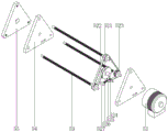
fig. 10 is a schematic view showing the structure of the anchoring mechanism of the present utility model in a disassembled state.
In the figure: 1. a base mechanism; 11. a chassis; 12. a damping wheel; 13. stabilizing the deployment arm; 14. a hydraulic support leg; 15. a storage battery; 16. a mounting tray; 2. a housing; 21. moving the handle; 3. a control panel; 4. a laser positioning assembly; 41. a transverse positioning line generator; 411. a lateral laser window; 42. a longitudinal positioning line generator; 421. a longitudinal laser window; 5. a propulsion mechanism; 51. a propulsion motor; 52. pushing the transmission assembly; 521. a main driving belt wheel; 522. a belt; 523. a screw rod driving belt wheel; 524. tensioning the belt pulley; 525. tensioning the sliding block; 526. tensioning a spring; 527. tensioning the fixed block; 53. pushing the screw rod; 54. pushing the fixing seat; 55. pushing the movable seat; 6. a limit rotating mechanism; 61. a limit rotating wheel; 62. a limiting rotating shaft; 63. a limit clamping groove; 64. limit reed; 7. a hardness detector; 8. a replaceable feeler lever; 9. an anchoring mechanism; 91. anchoring the fixed block; 92. anchoring the telescopic rod; 921. locking lines; 93. an anchor ring; 94. an anchor screw; 95. anchoring the locking block; 96. anchoring the lock nut; 97. a laser stand; 98. an anchor point laser pen.
Detailed Description
In order that the utility model may be more fully understood, a more particular description of the utility model will be rendered by reference to the appended drawings, in which several embodiments of the utility model are illustrated, but which may be embodied in different forms and are not limited to the embodiments described herein, which are, on the contrary, provided to provide a more thorough and complete disclosure of the utility model.
1-2, please refer to a material hardness detection system for building construction, including base unit 1, the top surface of base unit 1 is equipped with shell 2, the top surface one end of shell 2 inlays and is equipped with control panel 3, control panel 3's inside is equipped with the PLC controller, the one end of shell 2 is equipped with laser positioning component 4, the inside of shell 2 the top surface middle part of base unit 1 is equipped with propulsion mechanism 5, one side of propulsion mechanism 5 is equipped with spacing rotary mechanism 6, one side upper portion of spacing rotary mechanism 6 is equipped with hardness detector 7, the execution end of hardness detector 7 is equipped with removable feeler lever 8, one side of shell 2 is equipped with anchoring mechanism 9.
Referring to fig. 3, the base unit 1 includes a chassis 11, a plurality of shock absorbing wheels 12 are symmetrically disposed on two sides of the chassis 11, four corners of the chassis 11 are respectively rotatably connected with a stable unfolding arm 13, one ends of the plurality of stable unfolding arms 13 are respectively provided with a hydraulic support leg 14, a plurality of storage batteries 15 are disposed in the middle of the chassis 11, a mounting tray 16 is disposed outside the plurality of storage batteries 15, one end of the mounting tray 16 is disposed at the lower part of the laser positioning assembly 4, the bottom surface environment of a construction site is complex, and vibration of the device itself is reduced in the moving process by the plurality of shock absorbing wheels 12, so that equipment damage is avoided; the entire device is leveled and stably supported by a plurality of stable unfolding arms 13 respectively cooperating with hydraulic legs 14.
In the embodiment, please refer to fig. 4, two sides of one end of the housing 2 are symmetrically provided with a moving handle 21, respectively.
Referring to fig. 5, the laser positioning assembly 4 includes a transverse positioning line generator 41 and a longitudinal positioning line generator 42, one side of the transverse positioning line generator 41 is disposed at one side of one end of the housing 2, two transverse laser windows 411 are disposed in the middle of the transverse positioning line generator 41, the longitudinal positioning line generator 42 is disposed at one end of the base mechanism 1, three longitudinal laser windows 421 are disposed in the middle of the longitudinal positioning line generator 42, two transverse laser positioning lines are projected by the transverse positioning line generator 41, three longitudinal laser positioning lines are projected by the longitudinal positioning line generator 42, so as to obtain three cross laser positioning points, and three detection contacts corresponding to the hardness detector 7 and transformed by the limit rotating mechanism 6 are used for aiming at the positions required to be detected by the building facade.
In the embodiment, please refer to fig. 6-7, the pushing mechanism 5 includes a pushing motor 51, the pushing motor 51 is disposed at one end of the top surface of the base mechanism 1, the actuating end of the pushing motor 51 is coaxially connected with a pushing transmission assembly 52, the pushing transmission assembly 52 is in transmission connection with one ends of a plurality of pushing screws 53, two sides of the pushing transmission assembly 52 are respectively provided with a pushing fixing seat 54, one ends of the pushing screws 53 are rotatably connected to a triangle of the pushing fixing seats 54, the middle parts of the pushing screws 53 are respectively connected with a triangle of the pushing movable seat 55, the other ends of the pushing screws 53 are rotatably connected to the other end of the housing 2, the middle part of the pushing movable seat 55 is rotatably connected with the limit rotation mechanism 6, the pushing transmission assembly 52 includes a main transmission pulley 521, two ends of the main transmission pulley 521 are respectively rotatably connected with the middle parts of the pushing fixing seats 54, one ends of the main transmission pulley 521 are coaxially connected with the output ends of the pushing motor 51, the main transmission pulley 521 is rotatably connected with the middle parts of the belt transmission pulley 522, the tension blocks 522 are respectively provided with the tension blocks 522, the tension blocks 522 are rotatably connected with the two ends of the tensioning blocks 525 of the main transmission pulley 525 by the tension pulleys 525, one side of the tension blocks 525 are rotatably connected with the tension blocks 525, the tension blocks 522 are rotatably arranged under the tension blocks are rotatably and are rotatably connected with one side of the tension blocks 525 by the tension blocks 525, and are rotatably connected with one side of the tension blocks, and are rotatably connected with the tension blocks by the tension blocks, and the tension blocks are respectively, and the tension blocks are rotatably connected by tension blocks are rotatably by tension blocks and are respectively and are rotatably connected by tension by a tension pulley via a tension pulley. And then drive a plurality of propelling movement lead screws 53 to rotate, through the screw thread cooperation of a plurality of propelling movement lead screws 53 and propelling movement movable seat 55 to drive propelling movement movable seat 55 motion, and then drive hardness detector 7 and removable feeler lever 8 motion, thereby carry out hardness detection to the building facade.
Referring to fig. 8, the limit rotating mechanism 6 includes a limit rotating wheel 61, a middle portion of the limit rotating wheel 61 is coaxially connected with a limit rotating shaft 62, the limit rotating shaft 62 is rotatably connected to the middle portion of the pushing mechanism 5, a plurality of limit clamping grooves 63 are formed in an outer side of the limit rotating wheel 61, one of the limit clamping grooves 63 is clamped with one end of a limit reed 64, and the other end of the limit reed 64 is arranged on one side of the pushing mechanism 5.
Referring to fig. 9-10, the anchoring mechanism 9 includes an anchoring fixing block 91, one side of the anchoring fixing block 91 is disposed on one side of the housing 2, the anchoring fixing block 91 is slidably connected to the middle of the anchoring telescopic rod 92, one end of the anchoring telescopic rod 92 is provided with an anchoring ring 93, one end of the other side of the anchoring fixing block 91 is provided with an anchoring screw 94, the middle of the anchoring screw 94 is sleeved with an anchoring locking block 95, one side of the anchoring locking block 95 is in threaded connection with an anchoring locking nut 96, the other end of the other side of the anchoring fixing block 91 is connected with an anchoring point laser pen 98 through a laser bracket 97, one side of the anchoring telescopic rod 92 and the other side of the anchoring locking block 95 are respectively provided with locking lines 921, the design is that the anchoring point laser pen 98 is opened, an expansion bolt is installed by punching a building elevation at the anchoring point, the anchoring telescopic rod 92 is pulled out, the anchoring ring 93 is connected to the expansion bolt, then the anchoring nut 96 is screwed, and accordingly, the accurate detection of the data between the building elevation and the locking nut is ensured.
An embodiment, a hardness detection process for a material for building construction includes the following steps:
s1, stabilizing a base: according to the flatness of the elevation to be detected, the device is moved to a proper position, the distance is smaller than the telescopic length of the anchoring telescopic rod 92, the laser positioning assembly 4 is opened, the elevation of the building to be detected is aimed through a plurality of cross positioning lasers, a plurality of stable unfolding arms 13 are unfolded, and the device is leveled and stably supported through a plurality of hydraulic supporting legs 14;
s2, anchor point fixing: starting the anchoring point laser pen 98, finding an anchoring point by positioning the laser point, punching and installing an expansion bolt on the building elevation at the anchoring point, pulling out the anchoring telescopic rod 92, connecting the anchoring ring 93 to the expansion bolt, and then tightening the anchoring locking nut (96) to lock the anchoring telescopic rod (92);
s3, automatic detection: the replaceable feeler lever 8 is properly selected according to the distance, the propulsion motor 51 is started, the hardness detector 7 is propelled forwards through the propulsion mechanism 5 until the execution end of the replaceable feeler lever 8 contacts the building elevation to be detected to stop, and the hardness detector 7 resets through the propulsion mechanism 5 after completing data acquisition;
s4, changing the point positions: manually rotating the limit rotating wheel 61 to be clamped with one end of the limit reed 64 through the other limit clamping groove 63, so that the hardness detector 7 and the replaceable feeler lever 8 are rotated together to the position of the other detection point;
s5, repeated detection: repeating the steps S3 and S4 twice, and collecting hardness data of three detection points; s6, outputting data: a detection report is generated and the derived data file is displayed on the screen of the control panel 3, this design being passed.
Principle of operation: firstly, according to the flatness of a facade to be detected, the device is moved to a proper position, the distance is smaller than the telescopic length of an anchoring telescopic rod 92, a laser positioning assembly 4 is opened, the facade of the building to be detected is aimed through a plurality of cross positioning lasers, a plurality of stable unfolding arms 13 are unfolded, and the device is leveled and stably supported through a plurality of hydraulic supporting legs 14; by opening the anchoring point laser pen 98, locating an anchoring point by locating the laser point, punching and installing an expansion bolt on the building elevation at the anchoring point, pulling out the anchoring telescopic rod 92, connecting the anchoring ring 93 to the expansion bolt, and then tightening the anchoring locking nut 96 to lock the anchoring telescopic rod 92, thereby fixing the device and the building elevation with each other; according to the distance, a proper replaceable feeler lever 8 is selected, a propulsion motor 51 is started, a main driving belt pulley 521 is driven to rotate by the propulsion motor 51, a plurality of screw driving belt pulleys 523 are driven to rotate by a belt 522, a plurality of push screw rods 53 are driven to rotate, the push movable seat 55 is driven to move by the threaded fit of the plurality of push screw rods 53 and the push movable seat 55, and a hardness detector 7 and the replaceable feeler lever 8 are driven to move, so that hardness detection is carried out on a building elevation, and first point detection data are obtained; after reset, the limit rotating wheel 61 is manually rotated to be clamped with one end of the limit reed 64 through the other limit clamping groove 63, so that the hardness detector 7 and the replaceable feeler lever 8 are rotated to the position of the other detection positioning point; the propulsion motor 51 is started again to acquire second point detection data, and third point detection data is acquired by such pushing; finally, a detection report is generated, and the derived data file is displayed on the screen of the control panel 3, namely, the anchorage point positioning and three detection acquisition electric shock positioning are all achieved through laser projection aiming positioning, so that the method can be suitable for any irregular building elevation.
Claims (10)
1. A material hardness detecting system for construction is characterized in that: including base mechanism (1), the top surface of base mechanism (1) is equipped with shell (2), the top surface one end of shell (2) is inlayed and is equipped with control panel (3), the one end of shell (2) is equipped with laser positioning component (4), the inside of shell (2) the top surface middle part of base mechanism (1) is equipped with propulsion mechanism (5), one side of propulsion mechanism (5) is equipped with spacing rotary mechanism (6), one side upper portion of spacing rotary mechanism (6) is equipped with hardness detector (7), the execution end of hardness detector (7) is equipped with removable feeler lever (8), one side of shell (2) is equipped with anchor mechanism (9).
2. A system for hardness testing of a material for construction according to claim 1, wherein: the base mechanism (1) comprises a chassis (11), a plurality of shock absorption wheels (12) are symmetrically arranged on two sides of the chassis (11) respectively, four corners of the chassis (11) are respectively connected with a stable unfolding arm (13) in a rotating mode, one ends of the stable unfolding arms (13) are respectively provided with a hydraulic supporting leg (14), the middle of the chassis (11) is provided with a plurality of storage batteries (15), a plurality of storage batteries (15) are arranged outside an installation tray (16), and one end of the installation tray (16) is arranged on the lower portion of the laser positioning assembly (4).
3. A system for hardness testing of a material for construction according to claim 1, wherein: the two sides of one end of the shell (2) are symmetrically provided with movable handles (21) respectively.
4. A system for hardness testing of a material for construction according to claim 1, wherein: the laser positioning assembly (4) comprises a transverse positioning line generator (41) and a longitudinal positioning line generator (42), one side of the transverse positioning line generator (41) is arranged on one side of one end of the shell (2), two transverse laser windows (411) are arranged in the middle of the transverse positioning line generator (41), the longitudinal positioning line generator (42) is arranged at one end of the base mechanism (1), and three longitudinal laser windows (421) are arranged in the middle of the longitudinal positioning line generator (42).
5. A system for hardness testing of a material for construction according to claim 1, wherein: the pushing mechanism (5) comprises a pushing motor (51), the pushing motor (51) is arranged at one end of the top surface of the base mechanism (1), an executing end of the pushing motor (51) is coaxially connected with a pushing transmission assembly (52), one ends of a plurality of pushing screw rods (53) are connected through transmission of the pushing transmission assembly (52), pushing fixing seats (54) are respectively arranged at two sides of the pushing transmission assembly (52), one ends of the pushing screw rods (53) are rotationally connected to a plurality of triangular parts of the pushing fixing seats (54), a plurality of middle parts of the pushing screw rods (53) are respectively connected to triangular parts of pushing movable seats (55) through nuts, the other ends of the pushing screw rods (53) are rotationally connected to the other ends of the outer shell (2), and the middle parts of the pushing movable seats (55) are rotationally connected to the limiting rotating mechanism (6).
6. The system for detecting hardness of a material for construction according to claim 5, wherein: the pushing transmission assembly (52) comprises a main transmission belt wheel (521), two ends of the main transmission belt wheel (521) are respectively connected with the middle parts of a plurality of pushing fixing seats (54) in a rotating mode, one end of the main transmission belt wheel (521) is coaxially connected with the output end of the pushing motor (51), the main transmission belt wheel (521) is connected with a plurality of screw transmission belt wheels (523) through a belt (522) in a transmission mode, a tensioning belt wheel (524) is arranged in the middle of the belt (522), the tensioning belt wheel (524) is rotationally connected with the middle of a tensioning sliding block (525), two ends of the tensioning sliding block (525) are respectively connected with the lower parts of the pushing fixing seats (54) in a sliding mode, one side of the tensioning sliding block (525) is provided with a tensioning spring (526), one end of the tensioning spring (526) is arranged on one side of a tensioning fixing block (527), and two ends of the tensioning fixing block (527) are respectively arranged on the lower parts of the pushing fixing seats (54).
7. A system for hardness testing of a material for construction according to claim 1, wherein: the limiting rotating mechanism (6) comprises a limiting rotating wheel (61), the middle of the limiting rotating wheel (61) is coaxially connected with a limiting rotating shaft (62), the limiting rotating shaft (62) is rotationally connected to the middle of the propelling mechanism (5), a plurality of limiting clamping grooves (63) are formed in the outer side of the limiting rotating wheel (61), one limiting clamping groove (63) is clamped with one end of a limiting reed (64), and the other end of the limiting reed (64) is arranged on one side of the propelling mechanism (5).
8. A system for hardness testing of a material for construction according to claim 1, wherein: the utility model provides an anchor mechanism (9) is including anchor fixed block (91), one side of anchor fixed block (91) is located one side of shell (2), anchor fixed block (91) sliding connection is in the middle part of anchor telescopic link (92), the one end of anchor telescopic link (92) is equipped with anchor ring (93), the opposite side one end of anchor fixed block (91) is equipped with anchor screw rod (94), the middle part cover of anchor screw rod (94) is equipped with anchor locking piece (95), one side of anchor locking piece (95) one end threaded connection anchor locking nut (96) of anchor screw rod (94), the opposite side other end of anchor fixed block (91) passes through laser bracket (97) and connects anchor setpoint laser pen (98).
9. The system for detecting hardness of a material for construction according to claim 8, wherein: one side of the anchoring telescopic rod (92) and the other side of the anchoring locking block (95) are respectively provided with locking lines (921).
10. The process for detecting hardness of a material for construction according to claims 1 to 9, characterized in that: the method comprises the following steps:
s1, stabilizing a base: according to the flatness of the elevation to be detected, the device is moved to a proper position, the distance is smaller than the telescopic length of the anchoring telescopic rod (92), the laser positioning assembly (4) is opened, the elevation of the building to be detected is aimed through a plurality of cross positioning lasers, a plurality of stable unfolding arms (13) are unfolded, and the device is leveled and stably supported through a plurality of hydraulic supporting legs (14);
s2, anchor point fixing: starting the anchoring point laser pen (98), finding an anchoring point by positioning the laser point, punching and installing an expansion bolt on the building elevation at the anchoring point, pulling out the anchoring telescopic rod (92), connecting the anchoring ring (93) to the expansion bolt, and then tightening the anchoring locking nut (96) to lock the anchoring telescopic rod (92);
s3, automatic detection: the replaceable feeler lever (8) is properly arranged according to the distance, the propulsion motor (51) is started, the hardness detector (7) is propelled forwards through the propulsion mechanism (5) until the execution end of the replaceable feeler lever (8) is contacted with the building elevation to be detected to stop, and the hardness detector (7) resets through the propulsion mechanism (5) after data acquisition is completed;
s4, changing the point positions: manually rotating the limit rotating wheel (61) to be clamped with one end of the limit reed (64) through the other limit clamping groove (63), so that the hardness detector (7) and the replaceable feeler lever (8) are rotated to the position of the other detection point together;
s5, repeated detection: repeating the steps S3 and S4 twice, and collecting hardness data of three detection points;
s6, outputting data: a detection report is generated, and the derived data file is displayed on the screen of the control panel (3).
Priority Applications (1)
| Application Number | Priority Date | Filing Date | Title |
|---|---|---|---|
| CN202310392301.2A CN116429609A (en) | 2023-04-13 | 2023-04-13 | Material hardness detection system and detection process for building construction |
Applications Claiming Priority (1)
| Application Number | Priority Date | Filing Date | Title |
|---|---|---|---|
| CN202310392301.2A CN116429609A (en) | 2023-04-13 | 2023-04-13 | Material hardness detection system and detection process for building construction |
Publications (1)
| Publication Number | Publication Date |
|---|---|
| CN116429609A true CN116429609A (en) | 2023-07-14 |
Family
ID=87088658
Family Applications (1)
| Application Number | Title | Priority Date | Filing Date |
|---|---|---|---|
| CN202310392301.2A Pending CN116429609A (en) | 2023-04-13 | 2023-04-13 | Material hardness detection system and detection process for building construction |
Country Status (1)
| Country | Link |
|---|---|
| CN (1) | CN116429609A (en) |
Cited By (1)
| Publication number | Priority date | Publication date | Assignee | Title |
|---|---|---|---|---|
| CN117129310A (en) * | 2023-09-06 | 2023-11-28 | 江苏科泰检测技术服务有限公司 | Metal material hardness testing device and testing method thereof |
-
2023
- 2023-04-13 CN CN202310392301.2A patent/CN116429609A/en active Pending
Cited By (2)
| Publication number | Priority date | Publication date | Assignee | Title |
|---|---|---|---|---|
| CN117129310A (en) * | 2023-09-06 | 2023-11-28 | 江苏科泰检测技术服务有限公司 | Metal material hardness testing device and testing method thereof |
| CN117129310B (en) * | 2023-09-06 | 2024-03-22 | 广州威绰商品检测技术服务有限公司 | Metal material hardness testing device and testing method thereof |
Similar Documents
| Publication | Publication Date | Title |
|---|---|---|
| CN108827193B (en) | Detection device for accurately detecting flatness of template | |
| CN212672857U (en) | Total station | |
| CN105158096A (en) | Telescopic rebound detection device and use method thereof | |
| CN111076881B (en) | Intelligent deformation detection system for large building steel structure | |
| CN112068142A (en) | A loading platform for deep-water pile foundation sonar detection | |
| CN110987628B (en) | A photovoltaic tracking system bracket mechanical testing device and method | |
| CN214995269U (en) | Wallboard component reinforcing steel bar assembling device based on BIM technology | |
| CN112129650B (en) | A detection device for construction engineering supervision | |
| CN112986030B (en) | Mobile building structure detection robot | |
| CN223166460U (en) | Auxiliary device of concrete resiliometer | |
| CN119373107A (en) | A stable installation pile foundation structure for building construction | |
| CN219455070U (en) | Retaining wall inclinometry equipment | |
| CN217056967U (en) | Civil engineering construction measuring device | |
| CN117823765A (en) | A multifunctional concrete rebound strength detection device and detection method for residential buildings | |
| CN214832530U (en) | Static sounding instrument | |
| CN218916345U (en) | Data measuring instrument | |
| CN222616434U (en) | Building inclination measuring device for construction | |
| CN120739989B (en) | Laser detection device and method for crack width of wall body of dangerous house | |
| CN221006236U (en) | Measuring device for measuring earth excavation depth | |
| CN221038533U (en) | A intensity check out test set for bridge | |
| CN221280262U (en) | Constructional engineering perpendicularity detection device convenient to adjust | |
| CN220817145U (en) | Tunnel secondary lining detection equipment auxiliary device | |
| CN222798613U (en) | Bracket for building engineering inspection machine | |
| CN223400390U (en) | Measuring and positioning device | |
| CN216645320U (en) | Wall flatness detection device for construction engineering cost |
Legal Events
| Date | Code | Title | Description |
|---|---|---|---|
| PB01 | Publication | ||
| PB01 | Publication | ||
| SE01 | Entry into force of request for substantive examination | ||
| SE01 | Entry into force of request for substantive examination |