CN116357762A - A cage ball valve with regulating function - Google Patents
A cage ball valve with regulating function Download PDFInfo
- Publication number
- CN116357762A CN116357762A CN202310212716.7A CN202310212716A CN116357762A CN 116357762 A CN116357762 A CN 116357762A CN 202310212716 A CN202310212716 A CN 202310212716A CN 116357762 A CN116357762 A CN 116357762A
- Authority
- CN
- China
- Prior art keywords
- ball valve
- ball
- flow control
- valve
- channel
- Prior art date
- Legal status (The legal status is an assumption and is not a legal conclusion. Google has not performed a legal analysis and makes no representation as to the accuracy of the status listed.)
- Pending
Links
Images




Classifications
-
- F—MECHANICAL ENGINEERING; LIGHTING; HEATING; WEAPONS; BLASTING
- F16—ENGINEERING ELEMENTS AND UNITS; GENERAL MEASURES FOR PRODUCING AND MAINTAINING EFFECTIVE FUNCTIONING OF MACHINES OR INSTALLATIONS; THERMAL INSULATION IN GENERAL
- F16K—VALVES; TAPS; COCKS; ACTUATING-FLOATS; DEVICES FOR VENTING OR AERATING
- F16K5/00—Plug valves; Taps or cocks comprising only cut-off apparatus having at least one of the sealing faces shaped as a more or less complete surface of a solid of revolution, the opening and closing movement being predominantly rotary
- F16K5/06—Plug valves; Taps or cocks comprising only cut-off apparatus having at least one of the sealing faces shaped as a more or less complete surface of a solid of revolution, the opening and closing movement being predominantly rotary with plugs having spherical surfaces; Packings therefor
- F16K5/0605—Plug valves; Taps or cocks comprising only cut-off apparatus having at least one of the sealing faces shaped as a more or less complete surface of a solid of revolution, the opening and closing movement being predominantly rotary with plugs having spherical surfaces; Packings therefor with particular plug arrangements, e.g. particular shape or built-in means
-
- B—PERFORMING OPERATIONS; TRANSPORTING
- B01—PHYSICAL OR CHEMICAL PROCESSES OR APPARATUS IN GENERAL
- B01D—SEPARATION
- B01D35/00—Filtering devices having features not specifically covered by groups B01D24/00 - B01D33/00, or for applications not specifically covered by groups B01D24/00 - B01D33/00; Auxiliary devices for filtration; Filter housing constructions
- B01D35/02—Filters adapted for location in special places, e.g. pipe-lines, pumps, stop-cocks
- B01D35/04—Plug, tap, or cock filters filtering elements mounted in or on a faucet
-
- B—PERFORMING OPERATIONS; TRANSPORTING
- B08—CLEANING
- B08B—CLEANING IN GENERAL; PREVENTION OF FOULING IN GENERAL
- B08B1/00—Cleaning by methods involving the use of tools
- B08B1/10—Cleaning by methods involving the use of tools characterised by the type of cleaning tool
- B08B1/16—Rigid blades, e.g. scrapers; Flexible blades, e.g. wipers
- B08B1/165—Scrapers
-
- B—PERFORMING OPERATIONS; TRANSPORTING
- B08—CLEANING
- B08B—CLEANING IN GENERAL; PREVENTION OF FOULING IN GENERAL
- B08B1/00—Cleaning by methods involving the use of tools
- B08B1/20—Cleaning of moving articles, e.g. of moving webs or of objects on a conveyor
-
- F—MECHANICAL ENGINEERING; LIGHTING; HEATING; WEAPONS; BLASTING
- F16—ENGINEERING ELEMENTS AND UNITS; GENERAL MEASURES FOR PRODUCING AND MAINTAINING EFFECTIVE FUNCTIONING OF MACHINES OR INSTALLATIONS; THERMAL INSULATION IN GENERAL
- F16K—VALVES; TAPS; COCKS; ACTUATING-FLOATS; DEVICES FOR VENTING OR AERATING
- F16K47/00—Means in valves for absorbing fluid energy
- F16K47/02—Means in valves for absorbing fluid energy for preventing water-hammer or noise
-
- F—MECHANICAL ENGINEERING; LIGHTING; HEATING; WEAPONS; BLASTING
- F16—ENGINEERING ELEMENTS AND UNITS; GENERAL MEASURES FOR PRODUCING AND MAINTAINING EFFECTIVE FUNCTIONING OF MACHINES OR INSTALLATIONS; THERMAL INSULATION IN GENERAL
- F16K—VALVES; TAPS; COCKS; ACTUATING-FLOATS; DEVICES FOR VENTING OR AERATING
- F16K5/00—Plug valves; Taps or cocks comprising only cut-off apparatus having at least one of the sealing faces shaped as a more or less complete surface of a solid of revolution, the opening and closing movement being predominantly rotary
- F16K5/06—Plug valves; Taps or cocks comprising only cut-off apparatus having at least one of the sealing faces shaped as a more or less complete surface of a solid of revolution, the opening and closing movement being predominantly rotary with plugs having spherical surfaces; Packings therefor
- F16K5/0663—Packings
- F16K5/0689—Packings between housing and plug
-
- F—MECHANICAL ENGINEERING; LIGHTING; HEATING; WEAPONS; BLASTING
- F16—ENGINEERING ELEMENTS AND UNITS; GENERAL MEASURES FOR PRODUCING AND MAINTAINING EFFECTIVE FUNCTIONING OF MACHINES OR INSTALLATIONS; THERMAL INSULATION IN GENERAL
- F16K—VALVES; TAPS; COCKS; ACTUATING-FLOATS; DEVICES FOR VENTING OR AERATING
- F16K5/00—Plug valves; Taps or cocks comprising only cut-off apparatus having at least one of the sealing faces shaped as a more or less complete surface of a solid of revolution, the opening and closing movement being predominantly rotary
- F16K5/08—Details
- F16K5/10—Means for additional adjustment of the rate of flow
-
- F—MECHANICAL ENGINEERING; LIGHTING; HEATING; WEAPONS; BLASTING
- F16—ENGINEERING ELEMENTS AND UNITS; GENERAL MEASURES FOR PRODUCING AND MAINTAINING EFFECTIVE FUNCTIONING OF MACHINES OR INSTALLATIONS; THERMAL INSULATION IN GENERAL
- F16K—VALVES; TAPS; COCKS; ACTUATING-FLOATS; DEVICES FOR VENTING OR AERATING
- F16K5/00—Plug valves; Taps or cocks comprising only cut-off apparatus having at least one of the sealing faces shaped as a more or less complete surface of a solid of revolution, the opening and closing movement being predominantly rotary
- F16K5/08—Details
- F16K5/14—Special arrangements for separating the sealing faces or for pressing them together
- F16K5/20—Special arrangements for separating the sealing faces or for pressing them together for plugs with spherical surfaces
- F16K5/201—Special arrangements for separating the sealing faces or for pressing them together for plugs with spherical surfaces with the housing or parts of the housing mechanically pressing the seal against the plug
Landscapes
- Engineering & Computer Science (AREA)
- General Engineering & Computer Science (AREA)
- Mechanical Engineering (AREA)
- Water Supply & Treatment (AREA)
- Chemical & Material Sciences (AREA)
- Chemical Kinetics & Catalysis (AREA)
- Taps Or Cocks (AREA)
Abstract
Description
技术领域technical field
本发明涉及流体控制设备领域,更具体地说,它涉及一种具有调节功能的笼式球阀。The invention relates to the field of fluid control equipment, more specifically, it relates to a cage ball valve with regulating function.
背景技术Background technique
球阀,启闭件(球体)由阀杆带动,并绕球阀轴线作旋转运动的阀门。亦可用于流体的调节与控制,其中硬密封V型球阀其V型球芯与堆焊硬质合金的金属阀座之间具有很强的剪切力,特别适用于含纤维、微小固体颗料等的介质。而多通球阀在管道上不仅可灵活控制介质的合流、分流、及流向的切换,同时也可关闭任一通道而使另外两个通道相连。Ball valve, the opening and closing part (ball) is driven by the valve stem and rotates around the axis of the ball valve. It can also be used for the regulation and control of fluids, among which the hard-sealed V-shaped ball valve has a strong shear force between its V-shaped ball core and the metal valve seat of surfacing welding carbide, and is especially suitable for fibers and tiny solid particles. etc. medium. The multi-way ball valve can not only flexibly control the confluence, diversion, and flow direction switching of the medium on the pipeline, but also close any channel and connect the other two channels.
目前,在工业过程控制领域,以及在工业领域球阀以其良好的密封性,通流性,和可靠性及易维护等品质,具有广泛的应用空间。现有的具有调节性能的球阀在使用时,存在结构简单,流量调节精度低等弊端,使得操作者不能够准确的对流量进行控制,导致不能够计算流量和工作时间,在一些需要精确控制流量大小和计算时间的工作中,现有技术中普通球阀将会给操作者带来了许多不便,从而大大影响工作效率。因此,本领域技术人员提供了一种具有调节功能的笼式球阀,以解决上述背景技术中提出的问题。At present, in the field of industrial process control, as well as in the industrial field, ball valves have a wide range of application space due to their good sealing, flow, reliability and easy maintenance. The existing ball valves with regulating performance have disadvantages such as simple structure and low flow regulation accuracy, which make the operator unable to accurately control the flow rate, resulting in the inability to calculate the flow rate and working time. In the work of size and calculation time, the ordinary ball valve in the prior art will bring a lot of inconvenience to the operator, thereby greatly affecting the work efficiency. Therefore, those skilled in the art provide a caged ball valve with an adjustment function to solve the problems raised in the background art above.
中国专利公告号CN202022078132.X,公告日2021年05月14日,发明的名称为一种便于调节流量的球阀,包括球阀主体,所述球阀主体的顶端一侧固定安装有调节器,所述调节器的外端一侧设置有旋转把手,所述球阀主体的外端一侧设置有进水口,所述球阀主体的外端另一侧设置有出水口,所述旋转把手的外端一侧固定安装有蜗杆,且蜗杆贯穿调节器的内部一侧,所述球阀主体的内部一侧设置有阀杆,所述阀杆的外壁对应蜗杆的一侧固定安装有蜗轮齿轮,且蜗杆与蜗轮齿轮之间相互啮合。它存在结构简单,流量调节精度低弊端的不足。Chinese Patent Announcement No. CN202022078132.X, date of announcement: May 14, 2021, the name of the invention is a ball valve that facilitates flow adjustment, including a ball valve main body, a regulator is fixedly installed on the top side of the ball valve main body, and the adjustment One side of the outer end of the device is provided with a rotating handle, one side of the outer end of the ball valve main body is provided with a water inlet, and the other side of the outer end of the ball valve main body is provided with a water outlet, and the outer end side of the rotating handle is fixed A worm is installed, and the worm runs through the inner side of the regulator. The inner side of the ball valve body is provided with a valve stem. meshing with each other. It has the disadvantages of simple structure and low accuracy of flow regulation.
发明内容Contents of the invention
本发明克服了现有技术的具有调节性能的球阀在使用时,存在结构简单,流量调节精度低弊端的不足,提供了一种具有调节功能的笼式球阀,它能有效提高球阀的流量调节精度。The present invention overcomes the disadvantages of simple structure and low flow regulation precision in the prior art ball valves with regulation performance, and provides a cage ball valve with regulation function, which can effectively improve the flow regulation precision of ball valves .
为了解决上述技术问题,发明采用以下技术方案:一种具有调节功能的笼式球阀,包括:球阀壳体,包括一基本横向的球阀通道;In order to solve the above technical problems, the invention adopts the following technical solutions: a cage ball valve with adjustment function, comprising: a ball valve housing, including a substantially horizontal ball valve channel;
球芯体,呈球体结构,位于球阀通道中途位置处,包括贯穿球芯体两端的球体通道,用于协同球阀壳体,关闭所述球阀通道以及控制球阀通道内的流体流量;The ball core body has a spherical structure and is located in the middle of the ball valve channel, including ball channels running through both ends of the ball core body, used to cooperate with the ball valve housing to close the ball valve channel and control the fluid flow in the ball valve channel;
阀座,设置在球芯体两侧的球阀通道内,用于协同球芯体,精准调节球阀通道内的流体流量;The valve seat is set in the ball valve channel on both sides of the ball core body, and is used to cooperate with the ball core body to precisely adjust the fluid flow in the ball valve channel;
球阀阀杆,插于球阀壳体内,与球芯体腔内的球芯体固定连接,以相对球阀通道作回转运动,通过转动球阀阀杆可带动球芯体转动,使球体通道与阀座配合,实现球阀通道内的流量控制。The ball valve stem is inserted into the ball valve shell and fixedly connected with the ball core body in the ball core body cavity to make a rotary motion relative to the ball valve channel. By rotating the ball valve stem, the ball core body can be driven to rotate, so that the ball channel fits with the valve seat. Realize the flow control in the channel of the ball valve.
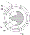
本发明提供了一种具有调节功能的笼式球阀,还包括通过若干螺栓固定安装在球阀壳体上的安装座,安装座上安装有控制开关组件,球阀阀杆一端插入到球阀壳体内与球芯体固定连接,且球阀阀杆与球阀壳体之间设有密封圈一,另一端穿过安装座与控制开关组件连接,该开关组件通过丝杠组件与球阀阀杆传动连接,使其可以相对球阀通道作回转运动。通过人工可控制开关组件调节球阀阀杆转动,进而带动球芯体转动,使球体通道与阀座配合,实现球阀通道内的流量控制;其中,丝杠传动结构属于现有技术,此处将不做赘述。阀座上设有控流孔,控流孔由一端呈v型的v型边,另一端呈向外凸出圆弧的扇形边,及连接扇形边两端与v型边开口端两边的两组连接边组合而成,该形状控流孔辅助球芯体,能够实现对流体流量的精准控制,同时还降低气蚀的发生。The invention provides a cage-type ball valve with adjustment function, which also includes a mounting seat fixedly installed on the ball valve housing through several bolts, a control switch assembly is installed on the mounting seat, and one end of the ball valve stem is inserted into the ball valve housing to connect with the ball valve. The core body is fixedly connected, and there is a sealing ring between the ball valve stem and the ball valve housing, and the other end is connected to the control switch assembly through the mounting seat. The switch assembly is connected to the ball valve stem through a screw assembly, so that it can Rotate relative to the ball valve channel. The rotation of the valve stem of the ball valve can be adjusted by manually controlling the switch assembly, and then the ball core is driven to rotate, so that the ball channel cooperates with the valve seat to realize the flow control in the ball valve channel; wherein, the screw transmission structure belongs to the prior art, and will not be discussed here. Do repeat. There is a flow control hole on the valve seat. The flow control hole consists of a V-shaped edge at one end, a fan-shaped edge with a protruding arc at the other end, and two ends connecting the two ends of the fan-shaped edge with the open ends of the V-shaped edge. The shape of the flow control hole assists the core body, which can realize precise control of the fluid flow and reduce the occurrence of cavitation at the same time.
作为优选,球阀壳体包括球阀阀体和球阀阀盖。球阀阀体与球阀阀盖之间通过若干螺栓进行固定连接,球阀阀盖可对球阀阀体内的球芯体进行限位固定,该结构设置便于球芯体及阀座的拆装更换。Preferably, the ball valve housing includes a ball valve body and a ball valve cover. The ball valve body and the ball valve cover are fixedly connected by several bolts. The ball valve cover can limit and fix the ball core in the ball valve body. This structure is convenient for the disassembly and replacement of the ball core and the valve seat.
作为优选,阀座包括控流板、若干设置在球阀壳体与控流板之间的弹性压紧件、及设置在控流板和球芯体之间的固定压板。球阀通道靠近球芯体一侧的壁体内设有呈环形结构阀座槽,阀座槽底壁内设有若干压紧件槽,压紧件槽沿周向等间距排布,固定压板为环形结构弹性密封件,固定压板一侧抵接在控流板上,使弹性压紧件压缩,另一侧与球芯体外侧球形面抵接,实现球芯体的球形面与两侧阀座始终贴紧连接,从而起到了对球芯体减震密封的作用;同时,球芯体在晃动时,球芯体和阀体可以同步相对调节,使控流板上控流孔与球体通道始终保持相对运动,进而提高了球阀通道内的流体流量的调节精度;还避免了球芯体在启闭过程中因容易产生晃动,导致控流孔摇摆不定,介质流通不顺畅,进而降低阀门使用寿命和问题。Preferably, the valve seat includes a flow control plate, several elastic pressing parts arranged between the ball valve housing and the flow control plate, and a fixed pressure plate arranged between the flow control plate and the ball core. The wall of the ball valve channel close to the ball core body is provided with a ring-shaped seat groove, and a number of pressing piece grooves are arranged in the bottom wall of the valve seat groove. The pressing piece grooves are arranged at equal intervals along the circumference, and the fixed pressure plate is ring Structural elastic seal, one side of the fixed pressure plate abuts against the flow control plate to compress the elastic compression part, and the other side abuts against the outer spherical surface of the ball core, so that the spherical surface of the ball core is always in contact with the valve seats on both sides. The connection is tight, so as to play the role of shock absorption and sealing for the ball core; at the same time, when the ball core is shaking, the ball core and the valve body can be adjusted synchronously, so that the flow control hole on the flow control plate and the ball channel are always maintained. The relative movement improves the adjustment accuracy of the fluid flow in the ball valve channel; it also avoids the ball core body from swaying easily during the opening and closing process, causing the flow control hole to sway, and the medium circulation is not smooth, thereby reducing the service life of the valve and question.
作为优选,控流板包括控流体、设置在控流体上的连接体及连接体上设有的刮刀体。该控流板上刮刀结构的设置,能够有效对球芯体的球形面上的介质进行清理,保证了球芯体调节的精度。Preferably, the flow control plate includes a control fluid, a connection body arranged on the control fluid, and a scraper body provided on the connection body. The setting of the scraper structure on the flow control plate can effectively clean the medium on the spherical surface of the spherical core body, thereby ensuring the adjustment accuracy of the spherical core body.
作为优选,连接体呈环形结构,连接体内环壁体连接在控流体外侧壁体上,控流体呈向远离球芯体外凸的弧形板结构。该弧形板结构的控流板的设计,可避免对球体结构的球芯体在相对控流板转动时造成干涉,该环形结构的连接体设计,可使其在与弹性压紧件配合时,周向各个位置的受力平衡,提高了对球芯体的减震密封作用。Preferably, the connecting body is in the form of a ring structure, the inner ring wall of the connecting body is connected to the outer wall of the control fluid, and the control fluid is in an arc-shaped plate structure protruding outward away from the ball core. The design of the flow control plate of the arc-shaped plate structure can avoid interference with the ball core body of the spherical structure when it rotates relative to the flow control plate. , The force balance of each position in the circumferential direction improves the shock-absorbing and sealing effect on the ball core.
作为优选,刮刀体为控流体与连接体连接处向球芯体一侧延伸形成,刮刀体端壁内设有呈弧形结构的刮刀面。提高了对球芯体外侧球形面的清理效果。Preferably, the scraper body is formed by extending from the joint between the control fluid and the connecting body to one side of the spherical core body, and an arc-shaped scraper surface is arranged inside the end wall of the scraper body. The cleaning effect on the outer spherical surface of the ball core body is improved.
作为优选,控流孔共一个,控流孔由一端到另一端呈逐渐扩大趋势。便于精确调节阀体通道内的流体流量。Preferably, there is one flow control hole, and the flow control hole gradually expands from one end to the other end. Facilitate precise adjustment of fluid flow in the valve body passage.
作为优选,若干控流孔组合后,在控流体上形成了一个呈菱形排布控流孔区域,控流孔区域的控流孔数量从一端到另一端呈逐渐增加趋势。该结的控流板自带筛网功能,防止介质含杂质导致球阀关不严。Preferably, after combining several flow control holes, a diamond-shaped flow control hole area is formed on the control fluid, and the number of flow control holes in the flow control hole area gradually increases from one end to the other end. The flow control plate of this junction has a screen function to prevent the ball valve from being closed tightly due to impurities in the medium.
作为优选,球体通道内设有过滤板,过滤板上设有若干过滤孔。实现杂质的二次过滤。Preferably, a filter plate is provided in the sphere channel, and several filter holes are provided on the filter plate. Realize the secondary filtration of impurities.
作为优选,固定压板与球阀阀体之间设有密封圈。该处橡胶材质的密封圈的设置,提高了阀座的密封性能及阀座的减震密封效果。Preferably, a sealing ring is provided between the fixed platen and the valve body of the ball valve. The setting of the sealing ring made of rubber here improves the sealing performance of the valve seat and the shock-absorbing and sealing effect of the valve seat.
与现有技术相比,发明的有益效果是:(1)在单独阀座上设置控流孔,可降低球阀的加工难度和成本降低;(2)球芯体两侧设有阀座,阀座通过弹性压紧件连接在球阀壳体上,可使阀座实现对球芯体的减震调节效果,进而避免了球芯体在启闭过程中因容易产生晃动,导致控流孔摇摆不定,介质流通不顺畅,进而降低阀门使用寿命和问题;(3) 通过球芯体和阀体同步相对调节配合,可使控流板上控流孔与球体通道始终保持相对运动,进而提高了球阀通道内的流体流量的调节精度;(4)控流板自带筛网功能,防止介质含杂质导致球阀关不严,同时可以降低气蚀的发生。Compared with the prior art, the beneficial effects of the invention are: (1) setting the flow control hole on the separate valve seat can reduce the processing difficulty and cost of the ball valve; (2) there are valve seats on both sides of the ball core, and the valve The seat is connected to the ball valve housing through elastic compression parts, so that the valve seat can realize the shock-absorbing adjustment effect on the ball core body, thereby avoiding the swaying of the ball core body during the opening and closing process, resulting in the swing of the flow control hole , the medium circulation is not smooth, which reduces the service life and problems of the valve; (3) Through the synchronous relative adjustment and cooperation between the ball core body and the valve body, the flow control hole on the flow control plate and the ball channel can always keep relative movement, thereby improving the ball valve. The adjustment accuracy of the fluid flow in the channel; (4) The flow control plate has a screen function to prevent the ball valve from being closed tightly due to impurities in the medium, and at the same time reduce the occurrence of cavitation.
附图说明Description of drawings
图1是发明的一种具有调节功能的笼式球阀的结构示意图;Fig. 1 is the structural representation of a kind of cage type ball valve with regulating function of the invention;
图2是发明的实施例1中的笼式球阀的结构示意图;Fig. 2 is the structural representation of the cage ball valve in the
图3是发明的实施例1中的笼式球阀的剖面图;Fig. 3 is the sectional view of the cage ball valve in the
图4是发明的实施例2中的笼式球阀的结构示意图;Fig. 4 is the structural representation of the cage ball valve in the
图5是发明的实施例2中的笼式球阀的剖面图;Fig. 5 is the sectional view of the cage ball valve in the
图6是发明的实施例1中的控流板的结构示意图;Fig. 6 is a schematic structural view of the flow control plate in
图中:球阀壳体1;球芯体2;阀座3;球阀阀体4;球阀阀盖5;球阀通道6;球芯体腔7;安装座8;开关组件9;球阀阀杆10;密封圈一11;球体通道12;v型边14;扇形边15;连接边16;控流板17;控流体18;连接体19;刮刀体20;弹性压紧件21;固定压板22;刮刀面23;密封圈24;阀座槽25;压紧件槽26;控流孔组28;过滤板29;过滤孔30。In the figure:
具体实施方式Detailed ways
应当理解,此处所描述的具体实施例仅仅用以解释本发明,并不用于限定本发明。It should be understood that the specific embodiments described here are only used to explain the present invention, not to limit the present invention.
下面通过具体实施例,并结合附图,对发明的技术方案作进一步的具体描述:Below by specific embodiment, in conjunction with accompanying drawing, the technical solution of the invention is described in further detail:
实施例1:一种具有调节功能的笼式球阀(参见附图1至附图3,附图6),包括:球阀壳体1、球芯体2及两组阀座3。球阀壳体1包括球阀阀体4和球阀阀盖5,球芯体2安装在球阀阀体4内,并通过球阀阀盖5进行限位固定,球阀阀体4与球阀阀盖5之间通过若干螺栓进行固定连接。阀座3分别固定设置在球芯体2两侧球阀阀体4和球阀阀盖5内,对球芯体2进行密封紧固,进而形成一种具有笼式结构的密封球阀。该结构设置便于球芯体2及阀座3的拆装更换。Embodiment 1: A cage-type ball valve with adjustment function (see accompanying
球阀壳体1内设置有一横向的球阀通道6,球阀通道6中途位置处设有球芯体腔7,球芯体2呈球体结构,设置在球芯体腔7内,球芯体2包括,用于协同球阀壳体1,关闭所述球阀通道6以及控制球阀通道6内的流体流量;The
还包括通过若干螺栓固定安装在球阀阀体4上的安装座8,安装座6上安装有开关组件9,球阀阀杆10,一端插入到球阀阀体4内与球芯体2固定连接,且球阀阀杆10与球阀阀体1之间设有密封圈一11,另一端穿过安装座6与开关组件9连接,该开关组件9通过丝杠组件与球阀阀杆10传动连接,使其可以相对球阀通道作回转运动。通过人工可控制开关组件9调节球阀阀杆10转动,进而带动球芯体2转动,使贯穿球芯体2两端的球体通道12与阀座3配合,实现球阀通道6内的流量控制。It also includes a mounting
阀座3,设置在球芯体2两侧的球阀通道6内,用于协同球芯体2,精准调节球阀通道6内的流体流量;具体包括控流孔13,控流孔13由一端呈v型的v型边14,另一端呈向外凸出圆弧的扇形边15,及连接扇形边15两端与v型边14开口端两边的两组连接边16组合而成,该形状控流孔辅助球芯体2,能够实现对流体流量的精准控制,同时还降低气蚀的发生。The
阀座还包括控流板17、设置在球阀壳体1与控流板17之间的弹性压紧件21、及设置在控流板17和球芯体2之间的固定压板22。The valve seat also includes a
控流板17,包括设置的控流孔13的控流体18、设置在控流体18上的连接体19及连接体19上设有的刮刀体20;连接体19呈环形结构,连接体19内环壁体连接在控流体18外侧壁体上,控流体18呈向远离球芯体2外凸的弧形板结构;该弧形板结构的控流板17的设计,可避免对球体结构的球芯体2在相对控流板转动时造成干涉,该环形结构的连接体19设计,可使其在与弹性压紧件21配合时,周向各个位置的受力平衡,提高了对球芯体2的减震密封作用;刮刀体20为控流体18与连接体19连接处向球芯体2一侧延伸形成,刮刀体20端壁内设有呈弧形结构的刮刀面23。控流板17上刮刀结构的设置,能够有效对球芯体2的球形面上的介质进行清理,保证了球芯体2调节的精度。The
固定压板22与球阀阀体4之间设有密封圈24。该处橡胶材质的密封圈24的设置,提高了阀座3的密封性能及阀座3的减震密封效果。球阀通道6靠近球芯体一侧的壁体内设有呈环形结构阀座槽25,阀座槽底25壁内设有若干压紧件槽26,压紧件槽26沿周向等间距排布,固定压板22呈环形结构,固定压板33一侧抵接在控流板17上,使弹性压紧件21压缩,另一侧与球芯体2外侧球形面抵接,实现球芯体2的球形面与两侧阀座3始终贴紧连接,从而起到了对球芯体2减震密封的作用;同时,球芯体2在晃动时,球芯体2和阀体3可以同步相对调节,使控流板17上控流孔13与球体通道12始终保持相对运动,进而提高了球阀通道6内的流体流量的调节精度;还避免了球芯体2在启闭过程中因容易产生晃动,导致控流孔13摇摆不定,介质流通不顺畅,进而降低阀门使用寿命和问题。A sealing
控流孔13共一个,控流孔13由一端到另一端呈逐渐扩大趋势。便于精确调节阀体通道6内的流体流量。There is one flow control hole 13, and the flow control hole 13 gradually expands from one end to the other end. It is convenient to precisely adjust the fluid flow in the channel 6 of the valve body.
实施例2Example 2
参见附图1,附图4,附图5及附图6,在实施例1的基础上不改变原控流孔区域外型的情况下,使单个控流孔改变成由若干个等间距布置控流孔组成控流孔组28,控流孔区域的控流孔数量从一端到另一端呈逐渐增加趋势。该结构的设置便于精确调节阀体通道内的流体流量;且该控流板自带筛网功能,防止介质含杂质导致球阀关不严。球体通道12内设有过滤板29,过滤板29上设有若干过滤孔30。实现杂质的二次过滤。Referring to accompanying drawing 1, accompanying drawing 4, accompanying drawing 5 and accompanying drawing 6, on the basis of
本发明的有益效果:(1)在单独阀座上设置控流孔,可降低球阀的加工难度和成本降低;(2)球芯体两侧设有阀座,阀座通过弹性压紧件连接在球阀壳体上,可使阀座实现对球芯体的减震调节效果,进而避免了球芯体在启闭过程中因容易产生晃动,导致控流孔摇摆不定,介质流通不顺畅,进而降低阀门使用寿命和问题;(3) 通过球芯体和阀体同步相对调节配合,可使控流板上控流孔与球体通道始终保持相对运动,进而提高了球阀通道内的流体流量的调节精度;(4)控流板自带筛网功能,防止介质含杂质导致球阀关不严,同时可以降低气蚀的发生。Beneficial effects of the present invention: (1) A flow control hole is set on a separate valve seat, which can reduce the processing difficulty and cost of the ball valve; (2) There are valve seats on both sides of the ball core body, and the valve seats are connected by elastic pressing parts On the ball valve shell, the valve seat can realize the shock-absorbing adjustment effect on the ball core body, thereby avoiding the swaying of the ball core body during the opening and closing process, which will cause the flow control hole to sway, and the medium flow is not smooth. Reduce the service life and problems of the valve; (3) Through the synchronous relative adjustment and cooperation of the ball core body and the valve body, the flow control hole on the flow control plate and the ball channel can always keep relative movement, thereby improving the regulation of the fluid flow in the ball valve channel Accuracy; (4) The flow control plate has its own screen function to prevent the ball valve from being closed tightly due to impurities in the medium, and can reduce the occurrence of cavitation at the same time.
以上所述的实施例只是发明较佳的方案,并非对发明作任何形式上的限制,在不超出权利要求所记载的技术方案的前提下还有其它的变体及改型。The embodiments described above are only preferred solutions for the invention, and do not limit the invention in any form. There are other variations and modifications on the premise of not exceeding the technical solutions described in the claims.
Claims (10)
Priority Applications (1)
| Application Number | Priority Date | Filing Date | Title |
|---|---|---|---|
| CN202310212716.7A CN116357762A (en) | 2023-03-01 | 2023-03-01 | A cage ball valve with regulating function |
Applications Claiming Priority (1)
| Application Number | Priority Date | Filing Date | Title |
|---|---|---|---|
| CN202310212716.7A CN116357762A (en) | 2023-03-01 | 2023-03-01 | A cage ball valve with regulating function |
Publications (1)
| Publication Number | Publication Date |
|---|---|
| CN116357762A true CN116357762A (en) | 2023-06-30 |
Family
ID=86911599
Family Applications (1)
| Application Number | Title | Priority Date | Filing Date |
|---|---|---|---|
| CN202310212716.7A Pending CN116357762A (en) | 2023-03-01 | 2023-03-01 | A cage ball valve with regulating function |
Country Status (1)
| Country | Link |
|---|---|
| CN (1) | CN116357762A (en) |
Cited By (1)
| Publication number | Priority date | Publication date | Assignee | Title |
|---|---|---|---|---|
| CN120231889A (en) * | 2025-05-29 | 2025-07-01 | 中国船舶集团有限公司第七一九研究所 | Regulating valves, water injection systems and ships |
Citations (10)
| Publication number | Priority date | Publication date | Assignee | Title |
|---|---|---|---|---|
| DE1500278A1 (en) * | 1964-08-26 | 1969-10-30 | Texsteam Corp | Throttle valves and corresponding valve seats |
| KR20110095767A (en) * | 2010-02-19 | 2011-08-25 | 동아대학교 산학협력단 | Double Ball Valve for Flow Control |
| CN102230544A (en) * | 2011-06-23 | 2011-11-02 | 浙江超达阀门股份有限公司 | Wear-resisting washing-resisting ball valve with flow regulating function |
| CN205155216U (en) * | 2015-11-02 | 2016-04-13 | 浙江永盛科技股份有限公司 | Adjustable flow ball valve |
| CN105526375A (en) * | 2014-09-28 | 2016-04-27 | 宁夏富隆德流体科技有限公司 | V-type adjusting ball valve |
| CN207814505U (en) * | 2018-01-19 | 2018-09-04 | 烟台金泰美林科技股份有限公司 | A kind of ceramic regulation globe valve valve seat |
| CN213393655U (en) * | 2020-10-30 | 2021-06-08 | 山东奥科自控设备有限公司 | Novel soft and hard sealing ball valve |
| CN214466262U (en) * | 2021-03-08 | 2021-10-22 | 厦门众博晟流体控制设备有限公司 | Ball valve with filtering capability |
| CN216430548U (en) * | 2021-07-06 | 2022-05-03 | 北京北高阀门有限公司 | Ball valve spheroid scraper structure and all-welded ball valve |
| RU2785978C1 (en) * | 2022-04-12 | 2022-12-15 | Федеральное государственное бюджетное образовательное учреждение высшего образования "Ярославский государственный технический университет" ФГБОУВО "ЯГТУ" | Control valve |
-
2023
- 2023-03-01 CN CN202310212716.7A patent/CN116357762A/en active Pending
Patent Citations (10)
| Publication number | Priority date | Publication date | Assignee | Title |
|---|---|---|---|---|
| DE1500278A1 (en) * | 1964-08-26 | 1969-10-30 | Texsteam Corp | Throttle valves and corresponding valve seats |
| KR20110095767A (en) * | 2010-02-19 | 2011-08-25 | 동아대학교 산학협력단 | Double Ball Valve for Flow Control |
| CN102230544A (en) * | 2011-06-23 | 2011-11-02 | 浙江超达阀门股份有限公司 | Wear-resisting washing-resisting ball valve with flow regulating function |
| CN105526375A (en) * | 2014-09-28 | 2016-04-27 | 宁夏富隆德流体科技有限公司 | V-type adjusting ball valve |
| CN205155216U (en) * | 2015-11-02 | 2016-04-13 | 浙江永盛科技股份有限公司 | Adjustable flow ball valve |
| CN207814505U (en) * | 2018-01-19 | 2018-09-04 | 烟台金泰美林科技股份有限公司 | A kind of ceramic regulation globe valve valve seat |
| CN213393655U (en) * | 2020-10-30 | 2021-06-08 | 山东奥科自控设备有限公司 | Novel soft and hard sealing ball valve |
| CN214466262U (en) * | 2021-03-08 | 2021-10-22 | 厦门众博晟流体控制设备有限公司 | Ball valve with filtering capability |
| CN216430548U (en) * | 2021-07-06 | 2022-05-03 | 北京北高阀门有限公司 | Ball valve spheroid scraper structure and all-welded ball valve |
| RU2785978C1 (en) * | 2022-04-12 | 2022-12-15 | Федеральное государственное бюджетное образовательное учреждение высшего образования "Ярославский государственный технический университет" ФГБОУВО "ЯГТУ" | Control valve |
Non-Patent Citations (1)
| Title |
|---|
| 沈新荣;潘康;单力钧;徐炜芳;: "调节型球阀流量特性的数值分析与实验研究", 流体传动与控制, no. 01, 15 January 2008 (2008-01-15) * |
Cited By (1)
| Publication number | Priority date | Publication date | Assignee | Title |
|---|---|---|---|---|
| CN120231889A (en) * | 2025-05-29 | 2025-07-01 | 中国船舶集团有限公司第七一九研究所 | Regulating valves, water injection systems and ships |
Similar Documents
| Publication | Publication Date | Title |
|---|---|---|
| CN210661460U (en) | Self-cleaning ball valve | |
| CN212407652U (en) | Middle annular surface sealing type diaphragm valve | |
| CN105003680A (en) | Half-ball valve | |
| CN108953662A (en) | A kind of cast steel metal sealing V-type ball valve | |
| CN207470808U (en) | A kind of Water flow adjusting valve | |
| CN212131375U (en) | A wear-resistant and corrosion-resistant ball valve | |
| CN110762269B (en) | A mechanical hydraulic valve that is easy to clean and disassemble | |
| CN114738498A (en) | Sewage overflow butterfly valve capable of cleaning sealing gap by automatic power | |
| CN213332468U (en) | Electric adjustable flange valve | |
| CN211693610U (en) | Bidirectional flow hard-touch hard-regulation type ball valve | |
| CN220320464U (en) | Butterfly valve convenient to adjust installation | |
| CN208295141U (en) | A kind of butterfly valve with filtering and cleaning function | |
| CN214331529U (en) | An N10 flow regulating and pressure regulating valve | |
| CN212584335U (en) | One-way sealing ball valve | |
| CN213685354U (en) | High platform V-shaped ball valve | |
| CN210164898U (en) | Stop valve for high-pressure regulation by using bevel gear | |
| CN210978552U (en) | Butterfly valve with stop device | |
| CN210240584U (en) | Butterfly valve | |
| CN220540330U (en) | Butterfly valve with sealing ring replaced without disassembly | |
| CN223019472U (en) | Eccentric semi-ball valve lined with fluorine | |
| CN213332506U (en) | Ball valve adaptable to different pipelines | |
| CN218913769U (en) | Butterfly valve with silt permeation prevention mechanism | |
| CN219432451U (en) | Bellows stop valve | |
| CN219975393U (en) | Sealing structure of butterfly valve | |
| CN214534554U (en) | Leakage-free split butterfly valve |
Legal Events
| Date | Code | Title | Description |
|---|---|---|---|
| PB01 | Publication | ||
| PB01 | Publication | ||
| SE01 | Entry into force of request for substantive examination | ||
| SE01 | Entry into force of request for substantive examination |