CN116352798A - Skin cutting equipment - Google Patents
Skin cutting equipment Download PDFInfo
- Publication number
- CN116352798A CN116352798A CN202310282927.8A CN202310282927A CN116352798A CN 116352798 A CN116352798 A CN 116352798A CN 202310282927 A CN202310282927 A CN 202310282927A CN 116352798 A CN116352798 A CN 116352798A
- Authority
- CN
- China
- Prior art keywords
- skin
- cutting
- support
- heating block
- cutting assembly
- Prior art date
- Legal status (The legal status is an assumption and is not a legal conclusion. Google has not performed a legal analysis and makes no representation as to the accuracy of the status listed.)
- Pending
Links
Images
Classifications
-
- B—PERFORMING OPERATIONS; TRANSPORTING
- B26—HAND CUTTING TOOLS; CUTTING; SEVERING
- B26D—CUTTING; DETAILS COMMON TO MACHINES FOR PERFORATING, PUNCHING, CUTTING-OUT, STAMPING-OUT OR SEVERING
- B26D11/00—Combinations of several similar cutting apparatus
-
- B—PERFORMING OPERATIONS; TRANSPORTING
- B26—HAND CUTTING TOOLS; CUTTING; SEVERING
- B26D—CUTTING; DETAILS COMMON TO MACHINES FOR PERFORATING, PUNCHING, CUTTING-OUT, STAMPING-OUT OR SEVERING
- B26D5/00—Arrangements for operating and controlling machines or devices for cutting, cutting-out, stamping-out, punching, perforating, or severing by means other than cutting
- B26D5/08—Means for actuating the cutting member to effect the cut
- B26D5/086—Electric, magnetic, piezoelectric, electro-magnetic means
-
- B—PERFORMING OPERATIONS; TRANSPORTING
- B26—HAND CUTTING TOOLS; CUTTING; SEVERING
- B26D—CUTTING; DETAILS COMMON TO MACHINES FOR PERFORATING, PUNCHING, CUTTING-OUT, STAMPING-OUT OR SEVERING
- B26D7/00—Details of apparatus for cutting, cutting-out, stamping-out, punching, perforating, or severing by means other than cutting
- B26D7/01—Means for holding or positioning work
- B26D7/02—Means for holding or positioning work with clamping means
-
- B—PERFORMING OPERATIONS; TRANSPORTING
- B26—HAND CUTTING TOOLS; CUTTING; SEVERING
- B26D—CUTTING; DETAILS COMMON TO MACHINES FOR PERFORATING, PUNCHING, CUTTING-OUT, STAMPING-OUT OR SEVERING
- B26D7/00—Details of apparatus for cutting, cutting-out, stamping-out, punching, perforating, or severing by means other than cutting
- B26D7/08—Means for treating work or cutting member to facilitate cutting
- B26D7/10—Means for treating work or cutting member to facilitate cutting by heating
-
- B—PERFORMING OPERATIONS; TRANSPORTING
- B26—HAND CUTTING TOOLS; CUTTING; SEVERING
- B26D—CUTTING; DETAILS COMMON TO MACHINES FOR PERFORATING, PUNCHING, CUTTING-OUT, STAMPING-OUT OR SEVERING
- B26D7/00—Details of apparatus for cutting, cutting-out, stamping-out, punching, perforating, or severing by means other than cutting
- B26D7/20—Cutting beds
-
- B—PERFORMING OPERATIONS; TRANSPORTING
- B26—HAND CUTTING TOOLS; CUTTING; SEVERING
- B26D—CUTTING; DETAILS COMMON TO MACHINES FOR PERFORATING, PUNCHING, CUTTING-OUT, STAMPING-OUT OR SEVERING
- B26D7/00—Details of apparatus for cutting, cutting-out, stamping-out, punching, perforating, or severing by means other than cutting
- B26D7/26—Means for mounting or adjusting the cutting member; Means for adjusting the stroke of the cutting member
- B26D7/2628—Means for adjusting the position of the cutting member
Landscapes
- Life Sciences & Earth Sciences (AREA)
- Forests & Forestry (AREA)
- Engineering & Computer Science (AREA)
- Mechanical Engineering (AREA)
- Physics & Mathematics (AREA)
- Optics & Photonics (AREA)
- Perforating, Stamping-Out Or Severing By Means Other Than Cutting (AREA)
Abstract
本发明实施例公开了一种切皮设备,用于导电件的外层绝缘皮切割,该切皮设备包括支架、支撑件和多个切皮机构,支撑件安装于支架,并用于支撑导电件,各切皮机构均安装于支架,并在导电件的周向间隔分布,各切皮机构中的至少一个具有驱动件,以使各切皮机构中的至少一个能够在驱动件的驱动下相对导电件靠近移动,以能够切割导电件的绝缘皮,通过在导电件的周向间隔分布多个切皮机构,使得导电件的绝缘皮能够切割,以使切皮设备的自动化程度较高,从而提高切皮效率。
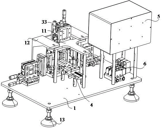
The embodiment of the present invention discloses a skin-cutting device, which is used for cutting the outer insulating skin of a conductive part. The skin-cutting device includes a bracket, a support part and a plurality of skin-cutting mechanisms. The support part is installed on the bracket and used to support the conductive part. , each skin-cutting mechanism is installed on the bracket, and is distributed in the circumferential direction of the conductive member at intervals, at least one of each skin-cutting mechanism has a driving member, so that at least one of each skin-cutting mechanism can be driven by the driving member. The conductive part moves close to the insulating skin of the conductive part, and by distributing a plurality of skin-cutting mechanisms at intervals in the circumferential direction of the conductive part, the insulating skin of the conductive part can be cut, so that the automation of the skin-cutting equipment is relatively high, thereby Improve skinning efficiency.
Description
技术领域technical field
本发明涉及电动汽车技术领域,尤其涉及一种切皮设备。The invention relates to the technical field of electric vehicles, in particular to a skin cutting device.
背景技术Background technique
电动汽车在生产的过程中,需要使用到母排或者硬排,软排或者硬排外层包裹有绝缘皮,为了是软排或者硬排能够与外部元件连接,需要将一部分绝缘皮进行切除。现有的切刀方式为上下各有一把一字型切刀,先对产品两面进行切割,再由手工采用壁纸刀具切割侧面,最后手工撕掉绝缘皮,切皮效率较低。In the production process of electric vehicles, busbars or hard bars need to be used. The outer layer of soft or hard bars is covered with insulation. In order for soft bars or hard bars to be connected to external components, part of the insulation needs to be cut off. The existing cutter method is to have a straight cutter at the top and bottom respectively, first cut the two sides of the product, then cut the side by hand with a wallpaper cutter, and finally tear off the insulating skin manually, the cutting efficiency is low.
发明内容Contents of the invention
基于此,有必要提供一种切皮设备,旨在解决现有的切刀方式为上下各有一把一字型切刀,先对产品两面进行切割,再由手工采用壁纸刀具切割侧面,最后手工撕掉绝缘皮,切皮效率较低的技术问题。Based on this, it is necessary to provide a kind of skin cutting equipment, which aims to solve the problem that the existing cutting knife method is to have a straight knife at the top and bottom, first cut the two sides of the product, then cut the side by hand with a wallpaper knife, and finally manually cut the two sides of the product. Tear off the insulation skin, the technical problem of low cutting efficiency.
本发明提供了一种切皮设备,用于导电件的外层绝缘皮切割,所述切皮设备包括支架、支撑件和多个切皮机构,所述支撑件安装于所述支架,并用于支撑所述导电件,各所述切皮机构均安装于所述支架,并在所述导电件的周向间隔分布,各所述切皮机构中的至少一个具有驱动件,以使各所述切皮机构中的至少一个能够在所述驱动件的驱动下相对所述导电件靠近移动,以能够切割所述导电件的绝缘皮。The invention provides a kind of skin cutting equipment, which is used for cutting the outer insulation skin of conductive parts. The skin cutting equipment includes a bracket, a support and a plurality of skin cutting mechanisms. Supporting the conductive member, each of the skin-cutting mechanisms is installed on the bracket and distributed at intervals in the circumferential direction of the conductive member, at least one of each of the skin-cutting mechanisms has a driving member, so that each of the skin-cutting mechanisms At least one of the skin-cutting mechanisms can be driven by the driving member to move closer to the conductive member, so as to be able to cut the insulating skin of the conductive member.
在其中一种实施例中,所述切皮机构的数量为四个,并分别为相对设置的第一切皮机构和第二切皮机构,以及相对设置的第三切皮机构和第四切皮机构,所述第一切皮机构包括第一驱动件和第一切皮组件,所述第二切皮机构包括第二驱动件和第二切皮组件,所述第三切皮机构包括第三驱动件和第三切皮组件,所述第四切皮机构包括第四切皮组件,所述第四切皮组件安装于所述支架,所述第一驱动件与所述第一切皮组件连接,并用于驱动所述第一切皮组件移动,所述第二驱动件与所述第二切皮组件连接,并用于驱动所述第二切皮组件移动,所述第三驱动件与所述第三切皮组件连接,并用于驱动所述第三切皮组件移动。In one of the embodiments, the number of the skin-cutting mechanisms is four, which are the first skin-cutting mechanism and the second skin-cutting mechanism which are oppositely arranged, and the third skin-cutting mechanism and the fourth skin-cutting mechanism which are oppositely arranged. Skin mechanism, the first skin-cutting mechanism includes a first driver and a first skin-cutting assembly, the second skin-cutting mechanism includes a second driver and a second skin-cutting assembly, and the third skin-cutting mechanism includes a first skin-cutting mechanism Three drivers and the third skin-cutting assembly, the fourth skin-cutting mechanism includes a fourth skin-cutting assembly, the fourth skin-cutting assembly is installed on the bracket, the first driver and the first skin-cutting The assembly is connected and used to drive the first skin-cutting assembly to move, the second driving member is connected to the second skin-cutting assembly and is used to drive the second skin-cutting assembly to move, and the third driving member is connected to the second skin-cutting assembly. The third skin cutting assembly is connected and used to drive the third skin cutting assembly to move.
在其中一种实施例中,所述第一切皮组件、所述第二切皮组件和所述第三切皮组件均包括第一加热件、第一加热块和第一切刀,所述第一加热件安装于所述第一加热块,并用于加热所述第一加热块,所述第一加热块与所述第一切刀连接,以能够将热量传导给所述第一切刀,所述第四切组件包括第二加热件、第二加热块和第二切刀,所述第二加热件安装于所述第二加热块,并用于加热所述第二加热块,所述第二加热块与所述第二切刀连接,以能够将热量传导给所述第二切刀。In one of the embodiments, the first skin-cutting assembly, the second skin-cutting assembly and the third skin-cutting assembly all include a first heating element, a first heating block, and a first cutter, and the The first heating element is installed on the first heating block and is used for heating the first heating block, and the first heating block is connected with the first cutter so as to conduct heat to the first cutter , the fourth cutting assembly includes a second heating element, a second heating block and a second cutting knife, the second heating element is installed on the second heating block, and is used to heat the second heating block, the The second heating block is connected with the second cutting knife to conduct heat to the second cutting knife.
在其中一种实施例中,所述第一切皮组件、所述第二切皮组件和所述第三切皮组件均包括连接板和第一隔热板,所述第一驱动件、所述第二驱动件和所述第三驱动件分别与对应的所述连接板连接,所述第一隔热板连接于所述连接板和所述第一加热块之间,所述第四切皮组件包括第二隔热板,所述第二隔热板连接于所述支架和所述第二加热块之间。In one of the embodiments, the first skin-cutting assembly, the second skin-cutting assembly and the third skin-cutting assembly all include a connecting plate and a first heat insulation board, and the first driving member, the The second driver and the third driver are respectively connected to the corresponding connection plate, the first heat shield is connected between the connection plate and the first heating block, and the fourth cut The skin assembly includes a second heat shield connected between the bracket and the second heating block.
在其中一种实施例中,所述第一切皮组件、所述第二切皮组件和所述第三切皮组件还均包括第一传感器,所述第一传感器用于感测所述第一加热块的温度值,所述第四切皮组件还包括第二传感器,所述第二传感器用于感测所述第二加热块的温度值。In one of the embodiments, the first skin-cutting assembly, the second skin-cutting assembly and the third skin-cutting assembly further include a first sensor, and the first sensor is used to sense the A temperature value of a heating block, the fourth skin cutting assembly further includes a second sensor, and the second sensor is used to sense the temperature value of the second heating block.
在其中一种实施例中,所述第三切皮机构还包括抵接件,所述抵接件与所述第三切皮组件连接,所述第三驱动件驱动所述第三切皮组件相对所述导电件靠近移动的过程中,所述抵接件与所述导电件抵接,以能够将所述导电件固定在所述抵接件和所述支撑件之间。In one of the embodiments, the third skin-cutting mechanism further includes an abutment, the abutment is connected with the third skin-cutting assembly, and the third driving member drives the third skin-cutting assembly In the process of moving closer to the conductive member, the abutting member abuts against the conductive member, so as to be able to fix the conductive member between the abutting member and the supporting member.
在其中一种实施例中,所述切皮设备还包括第一调节机构、第二调节机构和第三调节机构,所述第一调节机构与所述第一切皮机构连接,并用于调节所述第一切皮机构的位置,所述第二调节机构与所述第二切皮机构连接,并用于调节所述第二切皮机构的位置,所述第三调节机构与所述第三切皮机构连接,并用于调节所述第三切皮机构的位置。In one of the embodiments, the skin-cutting device further includes a first adjustment mechanism, a second adjustment mechanism and a third adjustment mechanism, the first adjustment mechanism is connected with the first skin-cut mechanism and is used to adjust the The position of the first skin-cutting mechanism, the second adjustment mechanism is connected with the second skin-cutting mechanism, and is used to adjust the position of the second skin-cutting mechanism, and the third adjustment mechanism is connected with the third skin-cutting mechanism. The leather mechanism is connected and used to adjust the position of the third skin-cutting mechanism.
在其中一种实施例中,所述第一调节机构、所述第二调节机构和所述第三调节机构均包括滑动台、底座、调节件和锁止件,所述第一驱动件、所述第二驱动件和所述第三驱动件分别与对应的所述滑动台连接,所述底座与所述滑动台滑动连接,所述调节件与所述底座连接,并与所述滑动台相抵,以能够调节所述滑动台的位置,所述锁止件与所述底座连接,并与所述滑动台相抵,以能够阻止所述滑动台移动。In one of the embodiments, the first adjustment mechanism, the second adjustment mechanism and the third adjustment mechanism all include a sliding table, a base, an adjustment member and a locking member, and the first driving member, the The second driving member and the third driving member are respectively connected to the corresponding sliding table, the base is slidingly connected to the sliding table, and the adjusting member is connected to the base and abuts against the sliding table , so as to be able to adjust the position of the sliding table, and the locking member is connected to the base and abuts against the sliding table, so as to prevent the sliding table from moving.
在其中一种实施例中,所述切皮设备还包括用于定位所述导电件位置的定位机构,所述定位机构包括支撑台、定位台、齿轮和手持件,所述支撑台设有限位凸起,所述定位台设有限位槽,所述限位凸起与所述限位槽的槽壁滑动连接,所述限位凸起设有齿条,所述齿轮与所述定位台旋转连接,并与所述齿条传动连接,所述齿轮与所述手持件连接,并至少部分露设所述定位台,转动所述手持件,以使所述齿轮能够相对所述定位台转动,以能够使所述定位台相对所述支撑台滑动。In one of the embodiments, the skin cutting equipment further includes a positioning mechanism for positioning the position of the conductive member, the positioning mechanism includes a support platform, a positioning platform, a gear and a handpiece, and the support platform is provided with a limit position The positioning platform is provided with a limiting groove, the limiting protrusion is slidably connected with the groove wall of the limiting groove, the limiting protrusion is provided with a rack, and the gear rotates with the positioning platform connected, and connected with the rack drive, the gear is connected with the handpiece, and at least partially exposes the positioning platform, and the handpiece is rotated so that the gear can rotate relative to the positioning platform, In order to enable the positioning platform to slide relative to the supporting platform.
在其中一种实施例中,所述定位机构还包括止动件,所述止动件与所述定位台连接,并与所述支撑台相抵,以能够阻止所述定位台相对所述支撑台移动。In one of the embodiments, the positioning mechanism further includes a stopper, and the stopper is connected with the positioning platform and abuts against the support platform so as to prevent the positioning platform from moving relative to the support platform. move.
实施本发明实施例,将具有如下有益效果:Implementing the embodiment of the present invention will have the following beneficial effects:
采用本发明的切皮设备,该切皮设备包括支架、支撑件和多个切皮机构,支撑件安装于支架,导电件放置在支撑件上,各切皮机构均安装于支架,并在导电件的周向间隔分布,各切皮机构中的至少一个具有驱动件,以使各切皮机构中的至少一个能够在驱动件的驱动下相对导电件靠近移动,以能够切割导电件的绝缘皮,通过在导电件的周向间隔分布多个切皮机构,使得导电件的绝缘皮能够切割,以使切皮设备的自动化程度较高,从而提高切皮效率。Adopt the skin-cutting equipment of the present invention, this skin-cutting equipment comprises support, support piece and a plurality of skin-cutting mechanism, and support piece is installed on support, and conductive piece is placed on support piece, and each skin-cutting mechanism is all installed on support, and conducts Circumferential interval distribution of parts, at least one of each skin-cutting mechanism has a driving part, so that at least one of each skin-cutting mechanism can be driven by the driving part to move closer to the conductive part, so as to be able to cut the insulating skin of the conductive part , by distributing a plurality of skin-cutting mechanisms at intervals in the circumferential direction of the conductive piece, the insulating skin of the conductive piece can be cut, so that the automation of the skin-cutting equipment is relatively high, thereby improving the efficiency of skin-cutting.
附图说明Description of drawings
为了更清楚地说明本发明实施例或现有技术中的技术方案,下面将对实施例或现有技术描述中所需要使用的附图作简单地介绍,显而易见地,下面描述中的附图仅仅是本发明的一些实施例,对于本领域普通技术人员来讲,在不付出创造性劳动的前提下,还可以根据这些附图获得其他的附图。In order to more clearly illustrate the technical solutions in the embodiments of the present invention or the prior art, the following will briefly introduce the drawings that need to be used in the description of the embodiments or the prior art. Obviously, the accompanying drawings in the following description are only These are some embodiments of the present invention. Those skilled in the art can also obtain other drawings based on these drawings without creative work.
其中:in:
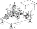
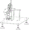
图1为一个实施例中切皮设备的轴测示意图。Fig. 1 is an axonometric schematic diagram of a skin-cutting device in an embodiment.
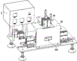
图2为图1所示切皮设备的另一角度示意图。Fig. 2 is a schematic diagram of another angle of the skin cutting device shown in Fig. 1 .
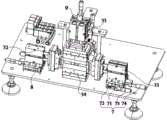
图3为图1所示切皮设备中第一切皮机构、第二切皮机构、第三切皮机构、第四切皮机构、第一调节机构、第二调节机构和第三调节机构的示意图。Fig. 3 is the structure of the first skin-cutting mechanism, the second skin-cutting mechanism, the third skin-cutting mechanism, the fourth skin-cutting mechanism, the first adjustment mechanism, the second adjustment mechanism and the third adjustment mechanism in the skin-cutting equipment shown in Fig. 1 schematic diagram.
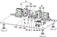
图4为图3所示切皮设备中第一切皮机构、第二切皮机构、第三切皮机构和支撑件的示意图。Fig. 4 is a schematic diagram of the first skin-cutting mechanism, the second skin-cutting mechanism, the third skin-cutting mechanism and the supporting member in the skin-cutting device shown in Fig. 3 .
图5为图3所示切皮设备中第三切皮机构、第四切皮机构和支撑件的示意图。Fig. 5 is a schematic diagram of the third skin-cutting mechanism, the fourth skin-cutting mechanism and the supporting member in the skin-cutting device shown in Fig. 3 .
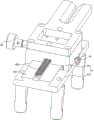
图6为图1所示切皮设备中定位机构的示意图。Fig. 6 is a schematic diagram of a positioning mechanism in the skin-cutting device shown in Fig. 1 .
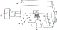
图7为图6所示定位机构中定位台、齿轮和手持件的示意图。Fig. 7 is a schematic diagram of the positioning platform, gears and hand piece in the positioning mechanism shown in Fig. 6 .
附图标记:Reference signs:
1、支架;11、支撑架;12、防护板;121、避让口;13、支撑脚;2、支撑件;1. Bracket; 11. Support frame; 12. Protective plate; 121. Avoidance port; 13. Support foot; 2. Support piece;
31、第一切皮机构;311、第一驱动件;312、第一切皮组件;3121、第一加热件;3122、第一加热块;3123、第一切刀;3124、连接板;3125、第一隔热板;3126、第一传感器;32、第二切皮机构;321、第二驱动件;322、第二切皮组件;33、第三切皮机构;331、第三驱动件;332、第三切皮组件;333、抵接件;34、第四切皮机构;341、第二加热件;342、第二加热块;343、第二切刀;344、第二隔热板;345、第二传感器;31. The first skin-cut mechanism; 311. The first driver; 312. The first skin-cut assembly; 3121. The first heating element; 3122. The first heating block; 3123. The first cutter; 3124. The connection plate; 3125 , the first heat shield; 3126, the first sensor; 32, the second skin-cutting mechanism; 321, the second driving member; 322, the second skin-cutting assembly; 33, the third skin-cutting mechanism; 331, the third driving member ; 332, the third skin-cutting assembly; 333, abutment piece; 34, the fourth skin-cutting mechanism; 341, the second heating element; 342, the second heating block; 343, the second cutter; 344, the second heat insulation board; 345, the second sensor;
4、定位机构;41、支撑台;411、限位凸起;412、齿条;42、定位台;421、限位槽;43、手持件;44、齿轮;45、止动件;5、控制箱;6、气动阀组;7、第一调节机构;71、滑动台;72、底座;73、调节件;74、锁止件;8、第二调节机构;9、第三调节机构。4. Positioning mechanism; 41. Support platform; 411. Limit protrusion; 412. Rack; 42. Positioning platform; 421. Limit slot; 43. Handpiece; 44. Gear; 45. Stopper; 5. Control box; 6. Pneumatic valve group; 7. First adjustment mechanism; 71. Slide table; 72. Base; 73. Adjustment piece; 74. Locking piece; 8. Second adjustment mechanism; 9. Third adjustment mechanism.
具体实施方式Detailed ways
下面将结合本发明实施例中的附图,对本发明实施例中的技术方案进行清楚、完整地描述,显然,所描述的实施例仅仅是本发明一部分实施例,而不是全部的实施例。基于本发明中的实施例,本领域普通技术人员在没有作出创造性劳动前提下所获得的所有其他实施例,都属于本发明保护的范围。The following will clearly and completely describe the technical solutions in the embodiments of the present invention with reference to the accompanying drawings in the embodiments of the present invention. Obviously, the described embodiments are only some, not all, embodiments of the present invention. Based on the embodiments of the present invention, all other embodiments obtained by persons of ordinary skill in the art without creative efforts fall within the protection scope of the present invention.
应注意到:相似的标号和字母在下面的附图中表示类似项,因此,一旦某一项在一个附图中被定义,则在随后的附图中不需要对其进行进一步定义和解释。It should be noted that like numerals and letters denote similar items in the following figures, therefore, once an item is defined in one figure, it does not require further definition and explanation in subsequent figures.
在本发明的描述中,需要说明的是,若出现术语“上”、“下”、“内”、“外”等指示的方位或位置关系为基于附图所示的方位或位置关系,或者是该发明产品使用时惯常摆放的方位或位置关系,仅是为了便于描述本发明和简化描述,而不是指示或暗示所指的装置或元件必须具有特定的方位、以特定的方位构造和操作,因此不能理解为对本发明的限制。In the description of the present invention, it should be noted that if the orientation or positional relationship indicated by the terms "upper", "lower", "inner" and "outer" appear, it is based on the orientation or positional relationship shown in the drawings, or It is the orientation or positional relationship that the invention product is usually placed in use, and it is only for the convenience of describing the present invention and simplifying the description, rather than indicating or implying that the referred device or element must have a specific orientation, be constructed and operated in a specific orientation , and therefore cannot be construed as a limitation of the present invention.
此外,若出现术语“第一”、“第二”等仅用于区分描述,而不能理解为指示或暗示相对重要性。In addition, terms such as "first" and "second" are used only for distinguishing descriptions, and should not be understood as indicating or implying relative importance.
需要说明的是,在不冲突的情况下,本发明的实施例中的特征可以相互结合。It should be noted that, in the case of no conflict, the features in the embodiments of the present invention may be combined with each other.
请一并结合图1至图7,现对本发明提供的切皮设备进行说明。切皮设备用于导电件的外层绝缘皮切割。切皮设备包括支架1、支撑件2和多个切皮机构,支撑件2安装于支架1,并用于支撑导电件,各切皮机构均安装于支架1,并在导电件的周向间隔分布,各切皮机构中的至少一个具有驱动件,以使各切皮机构中的至少一个能够在驱动件的驱动下相对导电件靠近移动,以能够切割导电件的绝缘皮。具体的,导电件用于电动汽车的软连接,具体为软母排或硬排,在本实施方式中,软母排或硬排的形状为四方体。Please refer to FIG. 1 to FIG. 7 together to describe the skin-cutting equipment provided by the present invention. Skin cutting equipment is used for cutting the outer insulation skin of conductive parts. The skin-cutting equipment includes a
可以理解的是,该切皮设备包括支架1、支撑件2和多个切皮机构,支撑件2安装于支架1,导电件放置在支撑件2上,各切皮机构均安装于支架1,并在导电件的周向间隔分布,各切皮机构中的至少一个具有驱动件,以使各切皮机构中的至少一个能够在驱动件的驱动下相对导电件靠近移动,以能够切割导电件的绝缘皮,通过在导电件的周向间隔分布多个切皮机构,使得导电件的绝缘皮能够切割,以使切皮设备的自动化程度较高,从而提高切皮效率。It can be understood that the skin-cutting equipment includes a
在本实施例中,切皮机构的数量为四个,并分别为相对设置的第一切皮机构31和第二切皮机构32,以及相对设置的第三切皮机构33和第四切皮机构34,第一切皮机构31包括第一驱动件311和第一切皮组件312,第二切皮机构32包括第二驱动件321和第二切皮组件322,第三切皮机构33包括第三驱动件331和第三切皮组件332,第四切皮机构34包括第四切皮组件,第四切皮组件安装于支架1,第一驱动件311与第一切皮组件312连接,并用于驱动第一切皮组件312移动,第二驱动件321与第二切皮组件322连接,并用于驱动第二切皮组件322移动,第三驱动件331与第三切皮组件332连接,并用于驱动第三切皮组件332移动。具体的,第一驱动件311、第二驱动件321和第三驱动件331可以为气缸。第一驱动件311能够驱动第一切皮组件312移动,第二驱动件321能够驱动第二切皮组件322移动,第三驱动件331能够驱动第三切皮组件332移动,导电件放置在支撑件2上,并将导电件绝缘皮需要切割的位置移动到第四切皮组件上,以使导电件的四个面能够切皮,从而使切皮设备的自动化程度较高。In the present embodiment, the number of skin-cutting mechanisms is four, and are respectively the first skin-cutting
进一步的,第一切皮组件312、第二切皮组件322和第三切皮组件332均相同,本实施方式中,以第一切皮组件312为例,第一切皮组件312包括第一加热件3121、第一加热块3122和第一切刀3123,第一加热件3121安装于第一加热块3122,并用于加热第一加热块3122,第一加热块3122与第一切刀3123连接,以能够将热量传导给第一切刀3123。Further, the first skin-cutting
具体的,第一加热件3121可以为加热棒,加热棒对第一加热块3122加热,第一加热块3122将热量传导给第一切刀3123,以使第一切刀3123在高温切皮后,能够使切面保持整洁,无划伤和切痕。第四切组件包括第二加热件341、第二加热块342和第二切刀343,第二加热件341安装于第二加热块342,并用于加热第二加热块342,第二加热块342与第二切刀343连接,以能够将热量传导给第二切刀343。具体的,第二加热件341可以为加热棒,加热棒对第二加热块342加热,第二加热块342将热量传导给第二切刀343,第二切刀343在高温切皮后,能够使切面保持整洁,无划伤和切痕。Specifically, the
在一实施例中,如图3至图5所示,第一切皮组件312、第二切皮组件322和第三切皮组件332均相同,本实施方式中,以第一切皮组件312为例,第一切皮组件312包括连接板3124和第一隔热板3125,第一驱动件311、第二驱动件321和第三驱动件331分别与对应的连接板3124连接,第一隔热板3125连接于连接板3124和第一加热块3122之间,以使第一加热块3122的热量能够隔绝,从而避免第一加热块3122的热量传导给驱动件。第四切皮组件包括第二隔热板344,第二隔热板344连接于支架1和第二加热块342之间,使得第二隔热板344能够隔绝第二加热块342的热量,以避免第二加热块342的热量传导给支架1。In one embodiment, as shown in FIGS. 3 to 5 , the first skin-cutting
在本实施例中,第一切皮组件312、第二切皮组件322和第三切皮组件332还均包括第一传感器3126,第一传感器3126用于感测第一加热块3122的温度值,以能够实时监测第一加热块3122的热量。第四切皮组件还包括第二传感器345,第二传感器345用于感测第二加热块342的温度值,以能够实时监测第二加热块342的热量。In this embodiment, the first skin-cutting
在一实施例中,如图4和图5所示,第三切皮机构33还包括抵接件333,抵接件333与第三切皮组件332连接,第三驱动件331驱动第三切皮组件332相对导电件靠近移动的过程中,抵接件333与导电件抵接,以能够将导电件固定在抵接件333和支撑件2之间。In one embodiment, as shown in FIG. 4 and FIG. 5 , the third skin-cutting
具体的,支撑件2安装于第二隔热板344上。第三驱动件331驱动第三切皮组件332向导电件靠近移动的过程中。第三切皮组件332会向导电件施加一定作用力,可能会导致导电件的部分脱离支撑件2,通过设置抵接件333,第三切皮组件332切皮时,抵接件333能够将导电件夹持在支撑件2上,从而避免导电件与支撑件2分离。Specifically, the
在一实施例中,如图3至图5所示,切皮设备还包括第一调节机构7、第二调节机构8和第三调节机构9,第一调节机构7与第一切皮机构31连接,并用于调节第一切皮机构31的位置,第二调节机构8与第二切皮机构32连接,并用于调节第二切皮机构32的位置,第三调节机构9与第三切皮机构33连接,并用于调节第三切皮机构33的位置。具体的,通过设置第一调节机构7、第二调节机构8和第三调节机构9,以能够调节第一切皮机构31、第二切皮机构32和第三切皮机构33的位置,可适应不同产品的切皮。In one embodiment, as shown in FIGS. 3 to 5 , the skin-cutting device further includes a
在本实施例中,第一调节机构7、第二调节机构8和第三调节机构9相同,以第一调节机构7为例,第一调节机构7包括滑动台71、底座72、调节件73和锁止件74,第一驱动件311、第二驱动件321和第三驱动件331分别与对应的滑动台71连接,底座72与滑动台71滑动连接,调节件73与底座72连接,并与滑动台71相抵,以能够调节滑动台71的位置,锁止件74与底座72连接,并与滑动台71相抵,以能够阻止滑动台71移动。In this embodiment, the
具体的,调节件73上设置有刻度,移动调节件73,使得滑动台71相对底座72移动,从而能够调节第一切皮机构31、第二切皮机构32和第三切皮机构33的位置,调节完成后,移动锁止件74,从而能够锁止滑动台71,滑动台71与底座72不会生产移动,以使第一驱动件311驱动第一切皮组件312、第二驱动件321驱动第二切皮组件322和第三驱动件331驱动第三切皮组件332的过程中,由于第一驱动件311、第二驱动件321和第三驱动件331移动行程为固定长度,滑动台71的位置固定后,从而使第一切皮组件312、第二切皮组件322和第三切皮组件332切皮后,不会对导电件切出划痕。Specifically, the
在一实施例中,如图1、图6和图7所示,切皮设备还包括用于定位导电件位置的定位机构4,定位机构4包括支撑台41、定位台42、齿轮44和手持件43,支撑台41设有限位凸起411,定位台42设有限位槽421,限位凸起411与限位槽421的槽壁滑动连接,限位凸起411设有齿条412,齿轮44与定位台42旋转连接,并与齿条412传动连接,齿轮44与手持件43连接,并至少部分露设定位台42,转动手持件43,以使齿轮44能够相对定位台42转动,以能够使定位台42相对支撑台41滑动。具体的,导电件放置于定位台42上,转动手持件43,手持件43驱动齿轮44相对定位台42旋转,齿轮44与齿条412传动连接,使得定位台42能够相对支撑台41相对移动,从而使限位凸起411能够与限位槽421的槽壁滑动,以能够调节导电件在各切皮机构的位置,从而切掉相应长度的绝缘皮。In one embodiment, as shown in Fig. 1, Fig. 6 and Fig. 7, the skin cutting equipment also includes a
在本实施例中,定位机构4还包括止动件45,止动件45与定位台42连接,并与支撑台41相抵,以能够阻止定位台42相对支撑台41移动。具体的,导电件调节好切皮位置后,扳动止动件45,使得定位台42能够锁止在支撑台41上,从而固定导电件的位置。In this embodiment, the
在一实施例中,如图1至图5所示,支架1还包括支撑架11、防护板12和支撑脚13,支撑架11安装于支架1上,第三切皮机构33安装于支撑架11上,支撑脚13与支架1连接,以支撑支架1。防护板12安装于支撑架11,防护板12还设有避让导电件的避让口121,防护板12能够隔档第一切皮机构31、第二切皮机构32、第三切皮机构33和第四切皮机构34,避免发生危险。In one embodiment, as shown in Figures 1 to 5, the
在本实施例中,切皮设备还包括控制箱5和气动阀组6,气动阀组6通过管路能够与第一驱动件311、第二驱动件321和第三驱动件331连通,控制箱5控制气动阀组6,以使第一驱动件311、第二驱动件321和第三驱动件331的伸缩。In this embodiment, the skin cutting equipment also includes a
本发明的工作流程为,确定切皮后导电件产品的尺寸,宽度和厚度,去皮长度等信息。将样品放到支撑件2上,以及第二切刀343上,在控制箱5的界面,点按钮控制气动阀组6,以使第一驱动件311驱动第一切皮组件312移动,第二驱动件321驱动第二切皮组件322移动,第三驱动件331驱动第三切皮组件332移动,以能够使第一切皮组件312、第二切皮组件322、第三切皮组件332和第四切皮组件接触样品;The working process of the present invention is to determine the size, width and thickness of the conductive member product after peeling, peeled length and other information. Put the sample on the
分别调整第一调节机构7、第二调节机构8和第三调节机构9,使得第一切皮机构31、第二切皮机构32第三切皮机构33和第四切皮机构34将产品加紧后,通过移动调节件73,使得第一切皮机构31、第二切皮机构32和第三切皮机构33远离产品0.02mm。调整完成后,移动锁止件74,使得第一切皮机构31、第二切皮机构32和第三切皮机构33锁紧在底座72上;Adjust the
在控制箱5界面,点按钮控制气动阀组6,以使第一驱动件311驱动第一切皮组件312移动,第二驱动件321驱动第二切皮组件322移动,第三驱动件331驱动第三切皮组件332移动,以能够使第一切皮组件312、第二切皮组件322和第三切皮组件332远离样品,拿下样品;On the
根据工艺参数调整控制箱5上的温度参数及保压时间;将导电件放到支撑件2上,以及第二切刀343上,导电件的一端设置在定位机构4上,调节定位机构4的位置,进而调节导电件的切皮长度,踩脚踏开关,以使第一驱动件311驱动第一切皮组件312移动,第二驱动件321驱动第二切皮组件322移动,第三驱动件331驱动第三切皮组件332移动,以能够使第一切皮组件312、第二切皮组件322和第三切皮组件332靠近导电件移动,第一切皮组件312、第二切皮组件322、第三切皮组件332和第四切皮组件同时切皮,保压1s后,第一驱动件311驱动第一切皮组件312移动,第二驱动件321驱动第二切皮组件322移动,第三驱动件331驱动第三切皮组件332移动,以能够使第一切皮组件312、第二切皮组件322和第三切皮组件332远离导电件移动。无需使用额外的工具,可根据切口,撕掉绝缘皮。Adjust the temperature parameters and pressure holding time on the
以上所述实施例的各技术特征可以进行任意的组合,为使描述简洁,未对上述实施例中的各个技术特征所有可能的组合都进行描述,然而,只要这些技术特征的组合不存在矛盾,都应当认为是本说明书记载的范围。The various technical features of the above-mentioned embodiments can be combined arbitrarily. To make the description concise, all possible combinations of the various technical features in the above-mentioned embodiments are not described. However, as long as there is no contradiction in the combination of these technical features, should be considered as within the scope of this specification.
以上所揭露的仅为本发明较佳实施例而已,当然不能以此来限定本发明之权利范围,因此依本发明权利要求所作的等同变化,仍属本发明所涵盖的范围。The above disclosures are only preferred embodiments of the present invention, and certainly cannot limit the scope of rights of the present invention. Therefore, equivalent changes made according to the claims of the present invention still fall within the scope of the present invention.
Claims (10)
Priority Applications (1)
| Application Number | Priority Date | Filing Date | Title |
|---|---|---|---|
| CN202310282927.8A CN116352798A (en) | 2023-03-22 | 2023-03-22 | Skin cutting equipment |
Applications Claiming Priority (1)
| Application Number | Priority Date | Filing Date | Title |
|---|---|---|---|
| CN202310282927.8A CN116352798A (en) | 2023-03-22 | 2023-03-22 | Skin cutting equipment |
Publications (1)
| Publication Number | Publication Date |
|---|---|
| CN116352798A true CN116352798A (en) | 2023-06-30 |
Family
ID=86941328
Family Applications (1)
| Application Number | Title | Priority Date | Filing Date |
|---|---|---|---|
| CN202310282927.8A Pending CN116352798A (en) | 2023-03-22 | 2023-03-22 | Skin cutting equipment |
Country Status (1)
| Country | Link |
|---|---|
| CN (1) | CN116352798A (en) |
Citations (6)
| Publication number | Priority date | Publication date | Assignee | Title |
|---|---|---|---|---|
| CN103737657A (en) * | 2013-12-31 | 2014-04-23 | 昆山宝良恒精密模具有限公司 | Cutting tool with heating system |
| CN106042432A (en) * | 2016-08-09 | 2016-10-26 | 南京润屹电子科技有限公司 | Travel-controllable pneumatic press |
| CN208758535U (en) * | 2018-09-12 | 2019-04-19 | 深圳弘威电业有限公司 | A kind of cable cutter inhibiting warpage |
| CN111884135A (en) * | 2020-07-31 | 2020-11-03 | 阜阳东胜汽车零部件有限责任公司 | Outer skin cutting tool for copper foil connecting wire |
| CN212399693U (en) * | 2020-06-18 | 2021-01-26 | 亳州联滔电子有限公司 | Wire peeling machine |
| CN217915507U (en) * | 2022-07-22 | 2022-11-29 | 深圳市锐巽自动化设备有限公司 | Peeling device for peeling electronic detonator |
-
2023
- 2023-03-22 CN CN202310282927.8A patent/CN116352798A/en active Pending
Patent Citations (6)
| Publication number | Priority date | Publication date | Assignee | Title |
|---|---|---|---|---|
| CN103737657A (en) * | 2013-12-31 | 2014-04-23 | 昆山宝良恒精密模具有限公司 | Cutting tool with heating system |
| CN106042432A (en) * | 2016-08-09 | 2016-10-26 | 南京润屹电子科技有限公司 | Travel-controllable pneumatic press |
| CN208758535U (en) * | 2018-09-12 | 2019-04-19 | 深圳弘威电业有限公司 | A kind of cable cutter inhibiting warpage |
| CN212399693U (en) * | 2020-06-18 | 2021-01-26 | 亳州联滔电子有限公司 | Wire peeling machine |
| CN111884135A (en) * | 2020-07-31 | 2020-11-03 | 阜阳东胜汽车零部件有限责任公司 | Outer skin cutting tool for copper foil connecting wire |
| CN217915507U (en) * | 2022-07-22 | 2022-11-29 | 深圳市锐巽自动化设备有限公司 | Peeling device for peeling electronic detonator |
Similar Documents
| Publication | Publication Date | Title |
|---|---|---|
| JP6287386B2 (en) | Deburring method for molded product, deburring table for molded product, and deburring device for molded product | |
| WO2001061277A3 (en) | Device, method and computer program product for altimetry system | |
| WO2018010136A1 (en) | Positioning device | |
| CN103042614B (en) | The special sizing device of multi-wire saw and using method thereof | |
| CN205817652U (en) | Positioning means | |
| EP3064478A1 (en) | Method and machine for cutting a glass sheet | |
| CN208450695U (en) | A kind of blank cutter with positioning fixture | |
| AU2003277938A1 (en) | Device for cutting glass and for removing a coating thereon | |
| CN117341076A (en) | Edge cutting equipment for photovoltaic module processing and working method thereof | |
| CN217891176U (en) | A strip cutting machine for poultry meat products with adjustable length and width | |
| JPS60191798A (en) | Method and device for cutting off printed circuit | |
| CN106182107A (en) | A kind of cable microtome | |
| CN218070830U (en) | A wire harness stripping machine with controllable stripping length | |
| CN210210600U (en) | Appearance workstation is cut in packaging design | |
| CN215471225U (en) | A turntable-based double gripper manipulator | |
| CN114966339A (en) | Fault detection device for insulation aging line of shear type transformer | |
| CN220261083U (en) | Cutting device is used in processing of waste film | |
| CN224183240U (en) | PE thermal shrinkage film slitting mechanism convenient for adjusting slitting width | |
| CN207807824U (en) | A kind of PET protection film cutter device | |
| CN223084869U (en) | Aerosol coated powder column peeling tool | |
| CN211334233U (en) | Film trimming mechanism capable of removing static electricity | |
| CN206250551U (en) | A kind of measurable pneumatic peeler of length | |
| CN218903807U (en) | Warm siphunculus cutting machine | |
| JP3603196B2 (en) | Cutting device and cutting method | |
| CN213857348U (en) | A cutting device for label processing |
Legal Events
| Date | Code | Title | Description |
|---|---|---|---|
| PB01 | Publication | ||
| PB01 | Publication | ||
| SE01 | Entry into force of request for substantive examination | ||
| SE01 | Entry into force of request for substantive examination |