CN116352687A - Free sliding structure of six-axis robot - Google Patents
Free sliding structure of six-axis robot Download PDFInfo
- Publication number
- CN116352687A CN116352687A CN202310645539.1A CN202310645539A CN116352687A CN 116352687 A CN116352687 A CN 116352687A CN 202310645539 A CN202310645539 A CN 202310645539A CN 116352687 A CN116352687 A CN 116352687A
- Authority
- CN
- China
- Prior art keywords
- shaft
- gear
- driving
- seat
- transmission
- Prior art date
- Legal status (The legal status is an assumption and is not a legal conclusion. Google has not performed a legal analysis and makes no representation as to the accuracy of the status listed.)
- Granted
Links
Images
Classifications
-
- B—PERFORMING OPERATIONS; TRANSPORTING
- B25—HAND TOOLS; PORTABLE POWER-DRIVEN TOOLS; MANIPULATORS
- B25J—MANIPULATORS; CHAMBERS PROVIDED WITH MANIPULATION DEVICES
- B25J9/00—Program-controlled manipulators
- B25J9/0009—Constructional details, e.g. manipulator supports, bases
-
- B—PERFORMING OPERATIONS; TRANSPORTING
- B25—HAND TOOLS; PORTABLE POWER-DRIVEN TOOLS; MANIPULATORS
- B25J—MANIPULATORS; CHAMBERS PROVIDED WITH MANIPULATION DEVICES
- B25J9/00—Program-controlled manipulators
- B25J9/10—Program-controlled manipulators characterised by positioning means for manipulator elements
- B25J9/102—Gears specially adapted therefor, e.g. reduction gears
-
- B—PERFORMING OPERATIONS; TRANSPORTING
- B25—HAND TOOLS; PORTABLE POWER-DRIVEN TOOLS; MANIPULATORS
- B25J—MANIPULATORS; CHAMBERS PROVIDED WITH MANIPULATION DEVICES
- B25J9/00—Program-controlled manipulators
- B25J9/10—Program-controlled manipulators characterised by positioning means for manipulator elements
- B25J9/12—Program-controlled manipulators characterised by positioning means for manipulator elements electric
- B25J9/123—Linear actuators
-
- B—PERFORMING OPERATIONS; TRANSPORTING
- B25—HAND TOOLS; PORTABLE POWER-DRIVEN TOOLS; MANIPULATORS
- B25J—MANIPULATORS; CHAMBERS PROVIDED WITH MANIPULATION DEVICES
- B25J9/00—Program-controlled manipulators
- B25J9/10—Program-controlled manipulators characterised by positioning means for manipulator elements
- B25J9/12—Program-controlled manipulators characterised by positioning means for manipulator elements electric
- B25J9/126—Rotary actuators
-
- Y—GENERAL TAGGING OF NEW TECHNOLOGICAL DEVELOPMENTS; GENERAL TAGGING OF CROSS-SECTIONAL TECHNOLOGIES SPANNING OVER SEVERAL SECTIONS OF THE IPC; TECHNICAL SUBJECTS COVERED BY FORMER USPC CROSS-REFERENCE ART COLLECTIONS [XRACs] AND DIGESTS
- Y02—TECHNOLOGIES OR APPLICATIONS FOR MITIGATION OR ADAPTATION AGAINST CLIMATE CHANGE
- Y02E—REDUCTION OF GREENHOUSE GAS [GHG] EMISSIONS, RELATED TO ENERGY GENERATION, TRANSMISSION OR DISTRIBUTION
- Y02E10/00—Energy generation through renewable energy sources
- Y02E10/50—Photovoltaic [PV] energy
Landscapes
- Engineering & Computer Science (AREA)
- Robotics (AREA)
- Mechanical Engineering (AREA)
- Gear Transmission (AREA)
Abstract
The invention discloses a free sliding structure of a six-axis robot, which relates to the technical field of six-axis robots. According to the invention, the base, the supporting seat, the connecting seat, the supporting column, the steering seat, the steering head and the power component are arranged, so that the multi-axis rotation of the robot can be realized, the multi-angle clamping adjustment of a workpiece can be realized, the power component can realize the adjustment of the angles between the supporting seat and the base as well as between the connecting seat and the supporting seat, and when the vertical height of the workpiece is required to be adjusted, the angles between the supporting seat and the base as well as between the connecting seat and the supporting seat are adjusted, so that the adjustment of the vertical height of the workpiece can be completed.
Description
Technical Field
The invention relates to the technical field of six-axis robots, in particular to a free sliding structure of a six-axis robot.
Background
Robots are increasingly important in modern industry, and with the development of industrial automation, intelligence and modernization, advanced robots gradually enter factories of modern industry, especially advanced manufacturing industry, and play an increasingly important role, such as automobile manufacturing industry, and rely on robots more and more. For the application of the robot in industry, the more dimensions the robot is required to be capable of freely controlling, the more the robot is capable of freely rotating in the axial direction or in the linear direction, and the more the dimensions are, the more the robot is capable of freely rotating in the axial direction or in the linear direction.
The Chinese patent 2017100806825 discloses a six-axis robot, which comprises a rotating seat, a swing arm, a bearing seat, a swing head, a first swing driving mechanism, a second swing driving mechanism, a rotary driving mechanism, a third swing driving mechanism and an end executing mechanism, wherein the swing arm is vertically arranged on the rotating seat and can horizontally rotate under the drive of the rotating seat; the first swing driving mechanism is arranged on the rotating seat and can drive the swing arm to swing back and forth; the second swing driving mechanism is arranged on the bearing seat, the swing head is arranged on the bearing seat through the rotary driving mechanism, and the second swing driving mechanism can drive the bearing seat to move so that the swing head swings up and down, and the rotary driving mechanism can drive the swing head to rotate; the third swing driving mechanism and the tail end executing mechanism are arranged on the swing head, and the third swing driving mechanism can also drive the tail end executing mechanism to swing up and down; the six-axis robot has high transmission precision and stable operation, can effectively avoid the situation of joint movement shake, but the device can not adaptively adjust the gravity center of the robot.
Chinese patent 2021111844672 discloses a high-speed six-axis robot comprising a bottom support member, a first axis member, a second axis member, a third axis member, a fourth axis member, a sixth axis member, a plurality of sets of stationary positioning members and a control module: the bottom support member includes a base for supporting and mounting the first shaft member; the first shaft moving part comprises a first shell, a second shell, a first rotating shaft, a first driving motor, a first bevel gear, a second bevel gear, a rotating support column and a rotating seat, wherein the first shell is fixedly arranged on the base and used for protecting the first rotating shaft and the second bevel gear in the first shell. The invention can solve the problems of large rotation inertia of each rotating shaft, poor dynamic performance of the mechanical arm and easy shaking of the upper arm and the lower arm, and avoid the continuous rotation of each rotating shaft by a certain angle after stopping, thereby not only being capable of being controlled remotely by people, but also being capable of sending out instructions by utilizing the automatic analysis and processing of the singlechip, and having strong integral load capacity, but the device can not be used for clamping the height of a workpiece.
In the current industrial application, the application of the multi-dimensional rotating robot is more common, wherein the six-axis robot is widely applied due to the higher degree of freedom, however, the six-axis robot still has some problems in practical application, such as the height adjustment range of the robot for clamping the workpiece is limited due to the fixed length of the vertical axis of the robot when the robot adjusts the height of the robot for clamping the workpiece.
Therefore, it is necessary to invent a free sliding structure of the six-axis robot to solve the above problems.
Disclosure of Invention
The present invention is directed to a free sliding structure of a six-axis robot, so as to solve the problems set forth in the above-mentioned background art.
In order to achieve the above purpose, the present invention provides the following technical solutions: the free sliding structure of the six-axis robot comprises a base, a supporting seat, a connecting seat, a pillar, a steering seat, a steering head and a power component, wherein the base, the supporting seat, the connecting seat, the pillar, the steering seat and the steering head are sequentially connected in series, the power component is arranged between the supporting seat and the connecting seat, the supporting seat comprises a supporting frame and a rotating shaft, and the supporting frame is arranged above the base;
the power assembly comprises a power box, the power box is arranged at the top end of a supporting frame, two symmetrically arranged transmission shafts are arranged in the power box, one end of each transmission shaft is movably arranged on the inner wall of the power box through a bearing, one side, close to each other, of each transmission shaft is provided with a hexagonal shaft, the outer side of each transmission shaft is sleeved with a movable sleeve, and the outer side of each movable sleeve is fixedly provided with a transmission bevel gear;
according to the invention, the support frame capable of sliding freely is arranged in the support seat, the driving gear and the driven gear are arranged on the support frame, the function of synchronous and opposite rotation of the worm gear transmission case and the connecting seat is realized by matching with the rotation of the adjusting screw, and meanwhile, the gravity center of the device can be effectively adjusted according to the inclination of the device under different states.
Preferably, the sliding connection has the support frame in the carriage, the rotation groove with the connecting axle intercommunication has been seted up to support frame one end, be equipped with the rotation subassembly in the rotation groove, the pivot passes through the rotation subassembly and is connected with the connecting axle rotation, the cover is equipped with driven gear in the rotation subassembly outside, the support frame other end is equipped with the screw thread piece with adjusting screw threaded connection, the screw thread piece top is equipped with the drive gear with driven gear intermeshing, be equipped with locking mechanism between drive gear and the screw thread piece, locking mechanism is used for controlling the connection and the disconnection of drive gear and screw thread piece, be equipped with in the drive gear with adjusting screw assorted spread groove.
Preferably, a sliding groove is formed in the top end of the inner side wall of the supporting frame, a supporting plate is arranged in the sliding groove, the supporting plate is of a U-shaped structure, the top end of the supporting plate is fixedly arranged at the bottom end of the power box, a transmission rod penetrates through the middle of the supporting plate through a bearing, and a transmission bevel gear is fixedly arranged at the top end of the transmission rod;
one end of the transmission shaft is fixedly provided with a driving bevel gear, the driving bevel gear is meshed with the transmission bevel gear, and one end of the other transmission shaft is fixedly provided with a transmission gear.
Preferably, one side of the transmission gear is provided with a connecting gear, one side of the connecting gear is fixedly provided with a rotating rod, the rotating rod is fixedly arranged on the inner side wall of the connecting seat, and the middle part of the rotating rod is provided with a first worm gear box.
Preferably, a through groove matched with the transmission shaft is formed in the middle of the movable sleeve in a penetrating manner, a limiting plate is fixedly arranged at one end of the movable sleeve, an electric push rod is arranged at one side of the limiting plate, and the electric push rod is fixedly arranged on the inner side wall of the power box;
the upper part of the movable sleeve is provided with a power shaft, the middle part of the power shaft is fixedly provided with two driving bevel gears, and the driving bevel gears are matched with the transmission bevel gears.
Preferably, a driving worm wheel is fixedly arranged at one end of the power shaft, a driving worm is arranged at one side of the driving worm wheel, a driving motor is fixedly arranged at one end of the driving worm, and the driving motor is fixedly arranged on the outer side wall of the power box.
Preferably, the bottom end fixing of carriage is provided with the second worm gear case, the output shaft of second worm gear case is fixed to be set up in the upper surface of base, the fixed pivot that is provided with of input shaft of second worm gear case, the fixed connecting axle that is provided with in top of pivot, the middle part of connecting axle is provided with the support frame through the bearing activity, and the fixed inner wall that sets up in the carriage of support frame.
Preferably, a slot with a hexagonal structure is formed in the middle of the bottom end of the transmission rod, and the slot is matched with the connecting shaft.
Preferably, the bottom of transfer line is provided with the extension frame, the lower surface of extension frame runs through and has seted up the screw thread groove, the inside of screw thread groove runs through and is provided with adjusting screw.
Preferably, the bottom end fixing of the adjusting screw is provided with an adjusting motor, and the adjusting motor is fixedly arranged in the supporting frame.
The invention has the technical effects and advantages that:
1. according to the invention, the base, the supporting seat, the connecting seat, the supporting column, the steering seat and the power assembly are arranged, so that the multi-axis rotation of the robot can be realized, the multi-angle clamping adjustment of a workpiece can be realized, the power assembly can realize the adjustment of the angles between the supporting seat and the base as well as between the connecting seat and the supporting seat, and when the vertical height of the workpiece is required to be adjusted, the angles between the supporting seat and the base as well as between the connecting seat and the supporting seat are adjusted, so that the adjustment of the vertical height of the workpiece can be completed.
2. According to the invention, the supporting seat is arranged, the supporting seat comprises the supporting frame, the supporting plate capable of sliding up and down is arranged on the supporting frame, the transmission rod is arranged in the middle of the supporting plate, the length of the supporting seat is adjusted by adjusting the position between the supporting plate and the supporting frame, and the vertical height of the robot can be adjusted, so that the six-axis robot can slide in the vertical direction, and the vertical height of a workpiece can be adjusted.
3. According to the invention, the power assembly is arranged, the power assembly can realize the power support for the angle adjustment of the supporting seat and the triaxial supporting seat, the power assembly comprises the power shaft and the transmission shafts, the two transmission shafts respectively realize the power output of the supporting seat and the triaxial supporting seat, the two transmission shafts are respectively connected with the power shaft through the two transmission bevel gears, the power output of the power assembly can be switched by adjusting the positions of the transmission bevel gears, the supporting seat and the triaxial supporting seat can be respectively controlled by adjusting the output switch of the power assembly, and the power assembly can realize the control of the supporting seat and the triaxial supporting seat through one power motor, so that the use amount of the motor is reduced, and the maintenance cost of the robot is reduced to a certain extent.
Drawings
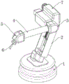
Fig. 1 is a schematic diagram of the overall structure of the present invention.
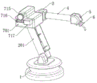
Fig. 2 is a schematic side view of the overall structure of the present invention.
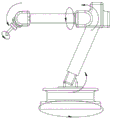
Fig. 3 is a schematic diagram of the motion trail of the whole structure of the present invention.
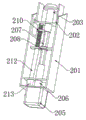
Fig. 4 is a schematic view of a supporting seat structure according to the present invention.
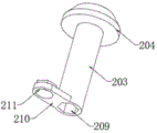
Fig. 5 is a schematic view of the structure of the transmission rod of the present invention.
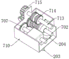
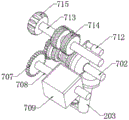
FIG. 6 is a schematic view of the interior of the power assembly of the present invention.
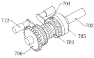
Fig. 7 is a schematic diagram of the positional relationship between a transmission shaft and a power shaft according to the present invention.
Fig. 8 is a schematic diagram of a transmission shaft structure of the present invention.
Fig. 9 is a schematic view of the structure of the transmission bevel gear of the present invention.
Fig. 10 is a schematic diagram of a transmission gear structure according to the present invention.
In the figure: 1. a base; 2. a support base; 3. a connecting seat; 4. a support post; 5. a steering seat; 6. a steering head; 7. a power assembly; 201. a support frame; 202. a support plate; 203. a transmission rod; 204. a drive bevel gear; 205. the second worm gear box; 206. a rotating shaft; 207. a connecting shaft; 208. a support frame; 209. a slot; 210. an extension frame; 211. a thread groove; 212. adjusting a screw; 213. adjusting a motor; 701. a power box; 702. a transmission shaft; 703. a movable sleeve; 704. a transmission helical gear; 705. driving a bevel gear; 706. a transmission gear; 707. a connecting gear; 708. a rotating rod; 709. the first worm gear box; 710. a through groove; 711. a limiting plate; 712. an electric push rod; 713. a power shaft; 714. a driving bevel gear; 715. a drive worm wheel; 716. driving a worm; 717. and driving the motor.
Detailed Description
The following description of the embodiments of the present invention will be made clearly and completely with reference to the accompanying drawings, in which it is apparent that the embodiments described are only some embodiments of the present invention, but not all embodiments. All other embodiments, which can be made by those skilled in the art based on the embodiments of the invention without making any inventive effort, are intended to be within the scope of the invention.
Example 1
The invention provides a free sliding structure of a six-axis robot as shown in fig. 1 to 10, which comprises a base 1, a supporting seat 2, a connecting seat 3, a support column 4, a steering seat 5, a steering head 6 and a power assembly 7, wherein the base 1, the supporting seat 2, the connecting seat 3, the support column 4, the steering seat 5 and the steering head 6 are sequentially connected in series, and the power assembly 7 is arranged between the supporting seat 2 and the connecting seat 3.
The support base 2 includes a support frame 201, and the support frame 201 is disposed above the base 1.
The spout has been seted up on the inside wall top of carriage 201, and is provided with backup pad 202 in the spout, backup pad 202 sets up to "U" shape structure, and the top of backup pad 202 is fixed to be set up in the bottom of power case 701, and backup pad 202 can slide in the inside of carriage 201 to make the position between carriage 201 and the power case 701 adjusted, the middle part of backup pad 202 runs through the bearing and is provided with transfer line 203, the fixed transmission bevel gear 204 that is provided with in top of transfer line 203.
Specifically, the bottom end fixing of the supporting frame 201 is provided with a second worm gear box 205, an output shaft of the second worm gear box 205 is fixedly arranged on the upper surface of the base 1, an input shaft of the second worm gear box 205 is fixedly provided with a rotating shaft 206, the top end of the rotating shaft 206 is fixedly provided with a connecting shaft 207, the middle part of the connecting shaft 207 is movably provided with a supporting frame 208 through a bearing, and the supporting frame 208 is fixedly arranged on the inner wall of the supporting frame 201.
More specifically, the middle of the bottom end of the transmission rod 203 is provided with a slot 209 with a hexagonal structure, and the slot 209 is matched with the connecting shaft 207, and the setting of the slot 209 enables the transmission rod 203 to drive the connecting shaft 207 to rotate.
And, the bottom of transfer line 203 is provided with extension frame 210, and the lower surface of extension frame 210 runs through and has seted up screw thread groove 211, and the inside of screw thread groove 211 runs through and is provided with adjusting screw 212, and adjusting screw 212 and screw thread groove 211 cooperation can realize the adjustment to extension frame 210 position.
Moreover, an adjusting motor 213 is fixedly arranged at the bottom end of the adjusting screw 212, and the adjusting motor 213 is fixedly arranged in the supporting frame 201, and the adjusting motor 213 can drive the adjusting screw 212 to rotate.
The power assembly 7 includes a power box 701, and the power box 701 is disposed at the top end of the support frame 201.
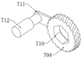
Specifically, the inside of the power box 701 is provided with two transmission shafts 702 which are symmetrically arranged, one end of each transmission shaft 702 is movably arranged on the inner wall of the power box 701 through a bearing, one side, close to each other, of each transmission shaft 702 is arranged as a hexagonal shaft, the outer side of each transmission shaft 702 is sleeved with a movable sleeve 703, and the outer side of each movable sleeve 703 is fixedly provided with a transmission bevel gear 704.
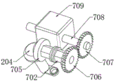
More specifically, one end of one transmission shaft 702 is fixedly provided with a drive bevel gear 705, and the drive bevel gear 705 is meshed with the drive bevel gear 204, and one end of the other transmission shaft 702 is fixedly provided with a drive gear 706.
And, one side of drive gear 706 is provided with connecting gear 707, connecting gear 707's one side is fixed to be provided with bull stick 708, and bull stick 708 is fixed to be set up in connecting seat 3's inside wall, and the middle part of bull stick 708 is provided with first worm gear case 709, and first worm gear case 709 has reached the auto-lock effect when realizing bull stick 708 power take off to the position locking of connecting seat 3 when having realized the transmission separation between power pack 7 and the connecting seat 3.
Moreover, the middle part of the movable sleeve 703 is provided with a through groove 710 adapted to the transmission shaft 702, one end of the movable sleeve 703 is fixedly provided with a limiting plate 711, one side of the limiting plate 711 is provided with an electric push rod 712, the electric push rod 712 is fixedly arranged on the inner side wall of the power box 701, the electric push rod 712 drives the limiting plate 711 to move, the limiting plate 711 can drive the transmission bevel gear 704 to slide horizontally, the transmission bevel gear 704 is separated from the driving bevel gear 714, at the moment, the transmission relation between the transmission shaft 702 and the power shaft 713 is relieved, and at the moment, the power assembly 7 can only adjust the angle between the supporting seat 2 and the base 1 or between the connecting seat 3 and the supporting seat 2.
Further, a power shaft 713 is disposed above the movable sleeve 703, two driving bevel gears 714 are fixedly disposed in the middle of the power shaft 713, and the driving bevel gears 714 are matched with the driving bevel gears 704, the power shaft 713 drives the driving bevel gears 714 to rotate, the driving bevel gears 714 drive the driving bevel gears 704 to rotate, the driving bevel gears 704 drive the movable sleeve 703 to rotate, the movable sleeve 703 drives the driving shaft 702 to rotate, and the two driving shafts 702 drive the driving bevel gears 705 and the driving bevel gears 706 to rotate respectively.
Furthermore, a driving worm wheel 715 is fixedly arranged at one end of the power shaft 713, a driving worm 716 is arranged at one side of the driving worm wheel 715, a driving motor 717 is fixedly arranged at one end of the driving worm 716, the driving motor 717 is fixedly arranged on the outer side wall of the power box 701, the driving motor 717 can drive the power shaft 713 to rotate through the driving worm 716 and the driving worm wheel 715, a self-locking effect is achieved between the driving worm 716 and the driving worm wheel 715, and self-locking between two shaft bodies of the robot can be achieved.
When the device is used, the angles among the base 1, the supporting seat 2, the connecting seat 3, the supporting column 4, the steering seat 5 and the steering head 6 can be respectively adjusted, so that the angle adjustment of the six-axis robot on a plurality of degrees of freedom can be realized, the adjustment of the workpiece clamping position can be realized, the power assembly 7 is arranged between the supporting seat 2 and the connecting seat 3, the adjustment of the angles among the supporting seat 2, the base 1, the connecting seat 3 and the supporting seat 2 can be realized, the angle among the supporting seat 2, the base 1, the connecting seat 3 and the supporting seat 2 can be simultaneously adjusted when the vertical height of a workpiece is required to be adjusted, the adjustment of the vertical height of the robot can be realized through adjusting the length of the supporting seat 2, the adjustment of the workpiece on the vertical height can be realized, and the levelness of the workpiece in the adjustment process is always kept motionless, so that the device has an influence on the workpiece when the workpiece position is adjusted as little as possible.
When the length of the supporting seat 2 is adjusted, the adjusting motor 213 drives the adjusting screw 212 to rotate, the adjusting screw 212 is matched with the thread groove 211, the extension frame 210 drives the transmission rod 203 to slide up and down, the transmission rod 203 can drive the supporting plate 202 to slide up and down, and accordingly the position between the supporting plate 202 and the supporting frame 201 is changed, and the supporting plate 202 is fixedly connected with the power assembly 7, and the supporting frame 201 is connected with the base 1, so that when the position of the supporting plate 202 is changed, the position between the base 1 and the power assembly 7 is changed, and the height of the device is adjusted.
When the power assembly 7 outputs power, the driving motor 717 drives the driving worm 716 to rotate, the driving worm 716 drives the driving worm wheel 715 to rotate, the driving worm wheel 715 drives the power shaft 713 to rotate, the power shaft 713 drives the driving bevel gear 714 to rotate, the driving bevel gear 714 drives the driving bevel gear 704 to rotate, the driving bevel gear 704 drives the movable sleeve 703 to rotate, the movable sleeve 703 drives the driving shaft 702 to rotate, and the two driving shafts 702 respectively drive the driving bevel gear 705 and the driving gear 706 to rotate.
The drive bevel gear 705 drives the drive bevel gear 204 to rotate, thereby driving the transmission rod 203 to rotate, and the transmission rod 203 can drive the connecting shaft 207 to rotate, and the connecting shaft 207 drives the input shaft of the second worm gear box 205 to rotate, so that the output shaft of the second worm gear box 205 rotates, and because the output shaft of the second worm gear box 205 is fixedly arranged on the base 1, the included angle between the supporting seat 2 and the base 1 changes at this time.
The transmission gear 706 drives the connecting gear 707 to rotate, the connecting gear 707 drives the rotating rod 708 to rotate, and the rotating rod 708 outputs power to the connecting seat 3 after passing through the first worm gear box 709, so that the angle between the power assembly 7 and the connecting seat 3 changes, and the angle between the supporting seat 2 and the connecting seat 3 can be adjusted because the power assembly 7 is connected with the top end of the supporting seat 2.
When only the angle between the supporting seat 2 and the base 1 or between the connecting seat 3 and the supporting seat 2 needs to be adjusted, the electric push rod 712 drives the limiting plate 711 to move, and the limiting plate 711 can drive the transmission bevel gear 704 to slide horizontally, so that the transmission bevel gear 704 is separated from the driving bevel gear 714, at this time, the transmission relationship between the transmission shaft 702 and the power shaft 713 is relieved, and at this time, the power assembly 7 can only adjust the angle between the supporting seat 2 and the base 1 or between the connecting seat 3 and the supporting seat 2.
Example two
In the practical use process, the operator finds that, because the rotation of the second worm gear box 205 and the connection seat 3 drives the power shaft 713 to rotate through the driving motor 717, the rotation directions of the second worm gear box 205 and the connection seat 3 are always consistent, and the second worm gear box 205 and the connection seat 3 cannot be simultaneously rotated reversely, so that the device cannot realize the cooperative linkage of the second worm gear box 205 and the connection seat 3 when clamping an object, and meanwhile, if the device clamps a heavier object, the gravity center of the device is deviated, the problem that the device is inclined or collapsed easily occurs, and the device is damaged.
The supporting frame 201 sliding connection has support frame 208, the rotation groove with connecting axle 207 intercommunication has been seted up to support frame 208 one end, be equipped with the rotating assembly in the rotation groove, pivot 206 is rotated with connecting axle 207 through the rotating assembly and is connected, the cover is equipped with driven gear in the rotating assembly outside, the support frame 208 other end is equipped with the screw thread piece with adjusting screw 212 threaded connection, the screw thread piece top is equipped with the drive gear with driven gear intermeshing, be equipped with locking mechanism between drive gear and the screw thread piece, locking mechanism is used for controlling the connection and the disconnection of drive gear and screw thread piece, be equipped with in the drive gear with adjusting screw 212 assorted spread groove.
Firstly, when the second worm gear box 205 and the connecting seat 3 need to move synchronously and in opposite directions, the electric push rod 712 connected with the driving bevel gear 705 is controlled to drive the driving bevel gear 704 to move in a direction far away from the driving bevel gear 714, the meshing relationship between the driving bevel gear 714 and the driving bevel gear 704 is released, at this time, the rotation of the power shaft 713 can only drive the connecting seat 3 to rotate positively or reversely, in the process, the connection between the driving gear and the threaded block is released by controlling the locking mechanism, the adjusting motor 213 is controlled to drive the adjusting screw 212 to rotate, at this time, the adjusting screw 212 drives the supporting frame 208 to move through the threaded block, meanwhile, due to the connecting groove matched with the adjusting screw 212 in the driving gear, the driving gear rotates along with the rotation of the adjusting screw 212 and drives the driven gear to rotate, so that the driven gear drives the connecting shaft 207 to rotate, and the connecting shaft 207 drives the second worm gear box 205 to rotate, thereby realizing the synchronous and opposite-direction cooperative movement of the second worm gear box 205 and the connecting seat 3, and simultaneously, when the rotation angle of the second worm box 205 is adjusted, the supporting frame 208 is synchronously controlled to slide in the supporting frame 201, and the gravity center of gravity of the device is prevented from tilting.
Secondly, when the device is used for clamping a far object and tilting, the supporting seat 2, the connecting seat 3, the support column 4, the steering seat 5 and the steering head 6 are positioned on the same side of the base 1, if tilting of the device is detected at this time, the adjusting screw 212 is controlled to rotate, the adjusting screw 212 drives the supporting frame 208 to move towards the second worm gear box 205, the gravity center of the device moves towards the base 1, meanwhile, the connecting shaft 207 is driven to rotate through the driving gear arranged on the supporting frame 208, the connecting shaft 207 drives the second worm gear box 205 to rotate towards the direction close to the base 1, in the process, the electric push rod 712 is controlled to be meshed with the transmission bevel gear 704 on one side of the driving bevel gear box 705, the rotating force of the connecting shaft 207 to the second worm gear box 205 is enhanced, the connecting shaft 207 can drive the second worm gear box 205 to rapidly rotate against the action of gravity, the fact that the device is tilted is effectively prevented, the connecting shaft 207 is excessively heavy due to the fact that the clamped object is loaded, the worm gear box 205 cannot rapidly reset, and simultaneously, the problem that the connecting shaft 713 can not be further rotated through the second worm gear box 713 is solved, and the tilting of the device can be further prevented from being synchronously rotated through the arrangement of the connecting shaft 713.
Finally, when the device is used for clamping and tilting a relatively heavy object, as shown in fig. 2, the supporting seat 2, the power assembly 7 and the connecting seat 3 are positioned on one side of the base 1, the supporting column 4, the steering seat 5 and the steering head 6 are positioned on the other side of the base 1, in this state, if the device is tilted, the control unit controls the adjusting screw 212 to drive the supporting frame 208 to move upwards, in this process, the control unit controls the threaded block to be interlocked with the driving gear through the locking mechanism, at the moment, the threaded block and the driving gear form a whole, and when the adjusting screw 212 drives the supporting frame 208 to move, the driving gear will not rotate, and meanwhile, the adjusting screw 212 moves the power assembly 7 connected with the supporting seat 2 to a direction away from the base 1 through the extension frame 210, so that the gravity center of the device is balanced, and the problem of tilting caused by gravity center deviation in the use process of the device is effectively prevented.
It should be noted that, according to the invention, the support frame 208 capable of sliding freely is arranged in the support seat 2, and the driving gear and the driven gear are arranged on the support frame 208, so that the synchronous and different-direction rotation functions of the second worm gear box 205 and the connecting seat 3 are realized by matching with the rotation of the adjusting screw 212, and meanwhile, the gravity center of the device can be effectively adjusted according to the inclination of the device under different states.
Finally, it should be noted that: the foregoing description is only illustrative of the preferred embodiments of the present invention, and although the present invention has been described in detail with reference to the foregoing embodiments, it will be apparent to those skilled in the art that modifications may be made to the embodiments described, or equivalents may be substituted for elements thereof, and any modifications, equivalents, improvements or changes may be made without departing from the spirit and principles of the present invention.
Claims (10)
1. The free sliding structure of the six-axis robot is characterized by comprising a base, a supporting seat, a connecting seat, a support column, a steering seat, a steering head and a power component, wherein the base, the supporting seat, the connecting seat, the support column, the steering seat and the steering head are sequentially connected in series, the power component is arranged between the supporting seat and the connecting seat, the supporting seat comprises a supporting frame and a rotating shaft, and the supporting frame is arranged above the base;
the power assembly comprises a power box, the power box is arranged at the top end of a supporting frame, two transmission shafts which are symmetrically arranged are arranged in the power box, one end of each transmission shaft is movably arranged on the inner wall of the power box through a bearing, one side, close to each other, of each transmission shaft is arranged to be a hexagonal shaft, a movable sleeve is sleeved on the outer side of each transmission shaft, and a transmission bevel gear is fixedly arranged on the outer side of each movable sleeve.
2. The free sliding structure of the six-axis robot according to claim 1, wherein: the supporting frame is connected with a supporting frame in a sliding mode, a rotating groove communicated with a connecting shaft is formed in one end of the supporting frame, a rotating assembly is arranged in the rotating groove, the rotating shaft is connected with the connecting shaft in a rotating mode through the rotating assembly, a driven gear is sleeved outside the rotating assembly, a thread block in threaded connection with an adjusting screw is arranged at the other end of the supporting frame, a driving gear meshed with the driven gear is arranged at the top of the thread block, a locking mechanism is arranged between the driving gear and the thread block, the locking mechanism is used for controlling connection and disconnection of the driving gear and the thread block, and a connecting groove matched with an adjusting screw is formed in the driving gear.
3. The free sliding structure of the six-axis robot according to claim 1, wherein: the top end of the inner side wall of the supporting frame is provided with a sliding groove, a supporting plate is arranged in the sliding groove, the supporting plate is of a U-shaped structure, the top end of the supporting plate is fixedly arranged at the bottom end of the power box, the middle part of the supporting plate is provided with a transmission rod in a penetrating manner through a bearing, and the top end of the transmission rod is fixedly provided with a transmission bevel gear;
one end of the transmission shaft is fixedly provided with a driving bevel gear, the driving bevel gear is meshed with the transmission bevel gear, and one end of the other transmission shaft is fixedly provided with a transmission gear.
4. A free sliding structure of a six-axis robot according to claim 3, characterized in that: one side of drive gear is provided with connecting gear, one side of connecting gear is fixed to be provided with the bull stick, and the bull stick is fixed to be set up in the inside wall of connecting seat, the middle part of bull stick is provided with first worm gear case.
5. The free sliding structure of the six-axis robot according to claim 1, wherein: the middle part of the movable sleeve is provided with a through groove matched with the transmission shaft in a penetrating way, one end of the movable sleeve is fixedly provided with a limiting plate, one side of the limiting plate is provided with an electric push rod, and the electric push rod is fixedly arranged on the inner side wall of the power box;
the upper part of the movable sleeve is provided with a power shaft, the middle part of the power shaft is fixedly provided with two driving bevel gears, and the driving bevel gears are matched with the transmission bevel gears.
6. The free sliding structure of the six-axis robot according to claim 5, wherein: one end of the power shaft is fixedly provided with a driving worm wheel, one side of the driving worm wheel is provided with a driving worm, one end of the driving worm is fixedly provided with a driving motor, and the driving motor is fixedly arranged on the outer side wall of the power box.
7. A free sliding structure of a six-axis robot according to claim 3, characterized in that: the bottom end fixing of carriage is provided with the second worm gear case, the fixed upper surface that sets up in the base of output shaft of second worm gear case, the fixed pivot that is provided with of input shaft of second worm gear case, the fixed connecting axle that is provided with in top of pivot, the middle part of connecting axle is provided with the support frame through the bearing activity, and the fixed inner wall that sets up in the carriage of support frame.
8. The free sliding structure of the six-axis robot as claimed in claim 7, wherein: the slot of hexagonal structure has been seted up at the bottom middle part of transfer line, and slot and connecting axle looks adaptation.
9. The free sliding structure of the six-axis robot according to claim 8, wherein: the bottom of transfer line is provided with the extension frame, the lower surface of extension frame runs through and has seted up the screw thread groove, the inside in screw thread groove runs through and is provided with adjusting screw.
10. The free sliding structure of the six-axis robot according to claim 9, wherein: the bottom end mounting of adjusting screw is provided with accommodate motor, and accommodate motor is fixed to be set up in the inside of braced frame.
Priority Applications (1)
| Application Number | Priority Date | Filing Date | Title |
|---|---|---|---|
| CN202310645539.1A CN116352687B (en) | 2023-06-02 | 2023-06-02 | Free sliding structure of six-axis robot |
Applications Claiming Priority (1)
| Application Number | Priority Date | Filing Date | Title |
|---|---|---|---|
| CN202310645539.1A CN116352687B (en) | 2023-06-02 | 2023-06-02 | Free sliding structure of six-axis robot |
Publications (2)
| Publication Number | Publication Date |
|---|---|
| CN116352687A true CN116352687A (en) | 2023-06-30 |
| CN116352687B CN116352687B (en) | 2023-07-25 |
Family
ID=86928605
Family Applications (1)
| Application Number | Title | Priority Date | Filing Date |
|---|---|---|---|
| CN202310645539.1A Active CN116352687B (en) | 2023-06-02 | 2023-06-02 | Free sliding structure of six-axis robot |
Country Status (1)
| Country | Link |
|---|---|
| CN (1) | CN116352687B (en) |
Citations (7)
| Publication number | Priority date | Publication date | Assignee | Title |
|---|---|---|---|---|
| AU2011100615A4 (en) * | 2011-05-26 | 2011-07-21 | Hengdian Group Linix Motor Co., Ltd. | Welding gun positioning mechanism |
| CN211662058U (en) * | 2019-12-31 | 2020-10-13 | 苏州浩智博智能科技有限公司 | A human-machine collaborative medical robot |
| CN212683965U (en) * | 2020-08-11 | 2021-03-12 | 河南工学院 | Robot gripper capable of grabbing goods at multiple angles |
| CN113334358A (en) * | 2021-06-18 | 2021-09-03 | 常州机电职业技术学院 | Mechanical arm convenient to adjust and using method |
| CN214490578U (en) * | 2021-01-25 | 2021-10-26 | 商丘工学院 | Workpiece transposition manipulator of hydraulic stretching machine |
| CN114083524A (en) * | 2021-12-02 | 2022-02-25 | 铂悦佳业(无锡)科技有限公司 | Six-degree-of-freedom control mechanical arm |
| CN114211474A (en) * | 2021-12-30 | 2022-03-22 | 廖金堂 | Mechanical arm with telescopic structure and capable of automatically grabbing |
-
2023
- 2023-06-02 CN CN202310645539.1A patent/CN116352687B/en active Active
Patent Citations (7)
| Publication number | Priority date | Publication date | Assignee | Title |
|---|---|---|---|---|
| AU2011100615A4 (en) * | 2011-05-26 | 2011-07-21 | Hengdian Group Linix Motor Co., Ltd. | Welding gun positioning mechanism |
| CN211662058U (en) * | 2019-12-31 | 2020-10-13 | 苏州浩智博智能科技有限公司 | A human-machine collaborative medical robot |
| CN212683965U (en) * | 2020-08-11 | 2021-03-12 | 河南工学院 | Robot gripper capable of grabbing goods at multiple angles |
| CN214490578U (en) * | 2021-01-25 | 2021-10-26 | 商丘工学院 | Workpiece transposition manipulator of hydraulic stretching machine |
| CN113334358A (en) * | 2021-06-18 | 2021-09-03 | 常州机电职业技术学院 | Mechanical arm convenient to adjust and using method |
| CN114083524A (en) * | 2021-12-02 | 2022-02-25 | 铂悦佳业(无锡)科技有限公司 | Six-degree-of-freedom control mechanical arm |
| CN114211474A (en) * | 2021-12-30 | 2022-03-22 | 廖金堂 | Mechanical arm with telescopic structure and capable of automatically grabbing |
Also Published As
| Publication number | Publication date |
|---|---|
| CN116352687B (en) | 2023-07-25 |
Similar Documents
| Publication | Publication Date | Title |
|---|---|---|
| US4502830A (en) | Industrial robot | |
| CN111730621A (en) | Manipulator of intelligent robot | |
| CN102380737A (en) | Oblique overturning displacement mechanism | |
| CN107283388A (en) | A kind of architectural engineering work machine | |
| CN108908292A (en) | A kind of mixed connection decoupling lathe that two turn of three shifting can be achieved | |
| CN112013879B (en) | A manual inertial navigation test turntable with high sensitivity | |
| CN116352687B (en) | Free sliding structure of six-axis robot | |
| CN121004630A (en) | Multi-directional adjustable mechanical gripper | |
| CN209504117U (en) | Compact industrial robot | |
| CN214136050U (en) | Telescopic arm lifting type power-assisted manipulator | |
| CN112976045B (en) | Mechanical arm is transported with production of mechanical lever axle | |
| CN108145732B (en) | Adjustable clamping moving manipulator | |
| CN217478460U (en) | Clamping and overturning equipment | |
| CN215968866U (en) | A focus adjustment mechanism for robot | |
| CN114772266A (en) | Clamping and overturning device | |
| KR102685843B1 (en) | Vertical articulated robot capable of varying speed and torque of end-effector | |
| EP0121576A1 (en) | Articulated arm type of industrial robot | |
| CN118418168A (en) | Large-opening rotary clamping jaw | |
| CN215478227U (en) | Manipulator for industrial automation | |
| CN118180740A (en) | Turnover welding robot and application method thereof | |
| CN223687623U (en) | Up, down, left, and right rotation adjustment positioning equipment | |
| CN219445100U (en) | Multifunctional arm | |
| CN114260929A (en) | Multi-angle grabbing mechanical device based on automatic robot | |
| CN220481713U (en) | Triaxial motion mechanical arm | |
| CN224129733U (en) | An adjustable horizontal flipping structure |
Legal Events
| Date | Code | Title | Description |
|---|---|---|---|
| PB01 | Publication | ||
| PB01 | Publication | ||
| SE01 | Entry into force of request for substantive examination | ||
| SE01 | Entry into force of request for substantive examination | ||
| GR01 | Patent grant | ||
| GR01 | Patent grant |