CN116338290A - A solenoid valve current detection method and system - Google Patents
A solenoid valve current detection method and system Download PDFInfo
- Publication number
- CN116338290A CN116338290A CN202310103555.8A CN202310103555A CN116338290A CN 116338290 A CN116338290 A CN 116338290A CN 202310103555 A CN202310103555 A CN 202310103555A CN 116338290 A CN116338290 A CN 116338290A
- Authority
- CN
- China
- Prior art keywords
- current
- solenoid valve
- signal
- tested
- current signal
- Prior art date
- Legal status (The legal status is an assumption and is not a legal conclusion. Google has not performed a legal analysis and makes no representation as to the accuracy of the status listed.)
- Pending
Links
Images


Classifications
-
- G—PHYSICS
- G01—MEASURING; TESTING
- G01R—MEASURING ELECTRIC VARIABLES; MEASURING MAGNETIC VARIABLES
- G01R19/00—Arrangements for measuring currents or voltages or for indicating presence or sign thereof
- G01R19/165—Indicating that current or voltage is either above or below a predetermined value or within or outside a predetermined range of values
- G01R19/16533—Indicating that current or voltage is either above or below a predetermined value or within or outside a predetermined range of values characterised by the application
-
- Y—GENERAL TAGGING OF NEW TECHNOLOGICAL DEVELOPMENTS; GENERAL TAGGING OF CROSS-SECTIONAL TECHNOLOGIES SPANNING OVER SEVERAL SECTIONS OF THE IPC; TECHNICAL SUBJECTS COVERED BY FORMER USPC CROSS-REFERENCE ART COLLECTIONS [XRACs] AND DIGESTS
- Y02—TECHNOLOGIES OR APPLICATIONS FOR MITIGATION OR ADAPTATION AGAINST CLIMATE CHANGE
- Y02T—CLIMATE CHANGE MITIGATION TECHNOLOGIES RELATED TO TRANSPORTATION
- Y02T10/00—Road transport of goods or passengers
- Y02T10/10—Internal combustion engine [ICE] based vehicles
- Y02T10/40—Engine management systems
Landscapes
- Physics & Mathematics (AREA)
- General Physics & Mathematics (AREA)
- Magnetically Actuated Valves (AREA)
- Testing And Monitoring For Control Systems (AREA)
Abstract
本申请提供一种电磁阀电流检测方法及系统,该方法包括:将电流传感器与待测电磁阀进行连接,以使电流传感器与待测电磁阀之间存在多路电流信号采集通道;随机选择一路电流信号采集通道进行导通,作为电流信号待测通道;采集电流信号待测通道上的电流信号,并将电流信号转换为电压信号;再对电压信号进行标定计算,获取与电压信号对应的电流值;将标定计算出的电流值分别与预设阈值进行比对,确定待测电磁阀是否发生故障。本申请可以采集电磁阀电流数据,并对异常电流数据进行报警,提示及时检查线路并维修;同时还可以与上位机进行数据传输,将采集的数据和判定结果通过串口通讯传送到上位机,实时监测电磁阀的电流数据和运行状态。
The application provides a solenoid valve current detection method and system, the method comprising: connecting the current sensor with the solenoid valve to be tested, so that there are multiple current signal acquisition channels between the current sensor and the solenoid valve to be tested; The current signal acquisition channel is turned on and used as the current signal channel to be tested; the current signal on the current signal channel to be tested is collected, and the current signal is converted into a voltage signal; then the voltage signal is calibrated and calculated to obtain the current corresponding to the voltage signal Value; compare the current value calculated by calibration with the preset threshold value to determine whether the solenoid valve to be tested is faulty. This application can collect solenoid valve current data, and give an alarm to abnormal current data, prompting timely inspection and maintenance of the line; at the same time, it can also perform data transmission with the host computer, and transmit the collected data and judgment results to the host computer through serial communication, real-time Monitor the current data and operating status of the solenoid valve.
Description
技术领域technical field
本申请涉及电磁阀检测技术领域,特别是涉及一种电磁阀电流检测方法及系统。The present application relates to the technical field of solenoid valve detection, in particular to a method and system for detecting solenoid valve current.
背景技术Background technique
电磁阀是自动化控制系统中一个主要执行件,在安全联锁保护过程中应用广泛。电磁阀作为安全联锁保护系统中的关键部件,其工作状态的启停与动作参量关系到整个系统的安全运行。因此,对电磁阀运行状态的监测对于大型设备安全、稳定、可靠运行具有非常重要的意义。Solenoid valve is a main executive part in automatic control system, and it is widely used in safety interlock protection process. As a key component in the safety interlock protection system, the solenoid valve's start-stop and action parameters in its working state are related to the safe operation of the entire system. Therefore, the monitoring of the operating state of the solenoid valve is of great significance for the safe, stable and reliable operation of large-scale equipment.
当前电磁阀的数据检测主要是通过现场工人巡检,工程师每天不定期的进行现场查看,并记录巡检数据,然后对记录数据进行整理分析电磁阀工作状态是否正常。这种检测方式即费时又费力,并且不能及时的得到检测结果。还有一种检测方式就是将检测电路串联到电磁阀电流回路中,但是这种方式需要提前预装或者停工停产安装,安装实施非常困难,非常不利于检测。At present, the data detection of solenoid valves is mainly through on-site worker inspections. Engineers inspect the site irregularly every day, record the inspection data, and then organize and analyze the recorded data to see if the solenoid valves are working normally. This detection method is time-consuming and laborious, and the detection result cannot be obtained in time. Another detection method is to connect the detection circuit in series to the current loop of the solenoid valve, but this method needs to be pre-installed in advance or shut down for installation, which is very difficult to install and implement, which is very unfavorable for detection.
发明内容Contents of the invention
鉴于以上所述现有技术的缺点,本申请的目的在于提供一种电磁阀电流检测方法及系统,用于解决现有技术中电磁阀检测费时费力以及不方便检测的问题。In view of the above-mentioned shortcomings of the prior art, the purpose of this application is to provide a solenoid valve current detection method and system for solving the problems of time-consuming, laborious and inconvenient detection of the solenoid valve in the prior art.
为实现上述目的及其他相关目的,本申请提供一种电磁阀电流检测方法,包括以下步骤:In order to achieve the above purpose and other related purposes, the present application provides a method for detecting the current of a solenoid valve, including the following steps:
将电流传感器与待测电磁阀进行连接,以使所述电流传感器与所述待测电磁阀之间存在多路电流信号采集通道;Connecting the current sensor to the solenoid valve to be tested, so that there are multiple current signal acquisition channels between the current sensor and the solenoid valve to be tested;
随机选择一路电流信号采集通道进行导通,作为电流信号待测通道;Randomly select a current signal acquisition channel to conduct as the current signal channel to be tested;
采集所述电流信号待测通道上的电流信号,并将所述电流信号转换为电压信号;Collecting the current signal on the channel to be measured of the current signal, and converting the current signal into a voltage signal;
对所述电压信号进行标定计算,获取与所述电压信号对应的电流值;performing calibration calculation on the voltage signal to obtain a current value corresponding to the voltage signal;
将标定计算出的电流值分别与第一阈值、第二阈值进行比对,确定所述待测电磁阀是否发生故障;若标定计算出的电流值大于所述第一阈值,或者标定计算出的电流值小于所述第二阈值,则确定所述待测电磁阀发生故障;其中,第一阈值大于第二阈值。Comparing the current value calculated by calibration with the first threshold value and the second threshold value respectively, to determine whether the solenoid valve to be tested is faulty; if the current value calculated by calibration is greater than the first threshold value, or the calculated current value by calibration If the current value is less than the second threshold, it is determined that the solenoid valve to be tested is faulty; wherein, the first threshold is greater than the second threshold.
可选地,若所述待测电磁阀未发生故障,则所述方法还包括:从所述多路电流信号采集通道中选择另外一路电流信号采集通道作为新的电流信号待测通道,并基于新的电流信号待测通道上的电流信号确定所述待测电磁阀是否发生故障。Optionally, if the electromagnetic valve to be tested is not faulty, the method further includes: selecting another current signal acquisition channel from the multiple current signal acquisition channels as a new current signal to be tested channel, and based on The current signal on the channel under test of the new current signal determines whether the solenoid valve under test fails.
可选地,若所述待测电磁阀发生故障,则所述方法还包括:基于引起所述待测电磁阀发生故障的电流信号生成报警信号;其中,所述报警信号包括以下至少之一:光信号、电控制器件信号。Optionally, if the electromagnetic valve to be tested fails, the method further includes: generating an alarm signal based on a current signal that causes the electromagnetic valve to be tested to fail; wherein the alarm signal includes at least one of the following: Optical signal, electrical control device signal.
可选地,基于引起所述待测电磁阀发生故障的电流信号生成报警信号时,包括:先生成光信号,再生成电控制器件信号;或者,生成电控制器件信号,再生成光信号。Optionally, when generating the alarm signal based on the current signal that causes the electromagnetic valve to be tested to fail, it includes: first generating an optical signal, and then generating an electrical control device signal; or generating an electrical control device signal, and then generating an optical signal.
可选地,所述光信号包括:发光二级管发光信号;所述电控制器件信号包括:继电器触电信号。Optionally, the optical signal includes: a light-emitting diode light-emitting signal; the electrical control device signal includes: a relay electric shock signal.
可选地,在生成报警信号后,所述方法还包括:Optionally, after the alarm signal is generated, the method further includes:
将引起所述待测电磁阀发生故障的电流信号、所述报警信号进行组装,形成数据帧;Assembling the current signal and the alarm signal causing the failure of the solenoid valve to be tested to form a data frame;
判断上位机通信串口是否存在数据帧请求;Determine whether there is a data frame request at the communication serial port of the upper computer;
如果所述上位机通信串口存在数据帧请求,则将所述数据帧通过所述上位机通信串口发送给上位机进行实时监测,并从所述多路电流信号采集通道中选择另外一路电流信号采集通道作为新的电流信号待测通道,并基于新的电流信号待测通道上的电流信号确定所述待测电磁阀是否发生故障;If there is a data frame request at the communication serial port of the upper computer, the data frame is sent to the upper computer through the communication serial port of the upper computer for real-time monitoring, and another current signal acquisition is selected from the multiple current signal acquisition channels The channel is used as a new current signal channel to be tested, and based on the current signal on the new current signal channel to be tested, it is determined whether the solenoid valve to be tested fails;
如果所述上位机通信串口不存在数据帧请求,则从所述多路电流信号采集通道中选择另外一路电流信号采集通道作为新的电流信号待测通道,并基于新的电流信号待测通道上的电流信号确定所述待测电磁阀是否发生故障。If there is no data frame request at the communication serial port of the upper computer, then select another current signal acquisition channel from the multiple current signal acquisition channels as a new current signal channel to be tested, and based on the new current signal channel to be tested The electric current signal determines whether the electromagnetic valve under test fails.
可选地,所述方法还包括:存储在每一路电流信号采集通道上采集的电流信号以及转换后的电压信号;以及,存储与每一路电流信号采集通道所对应的电磁阀故障检测结果。Optionally, the method further includes: storing the current signal collected on each current signal collection channel and the converted voltage signal; and storing the electromagnetic valve fault detection result corresponding to each current signal collection channel.
本申请还提供一种电磁阀电流检测系统,所述系统包括有:The present application also provides a solenoid valve current detection system, the system includes:
通讯模块,用于将电流传感器与待测电磁阀进行连接,以使所述电流传感器与所述待测电磁阀之间存在多路电流信号采集通道;The communication module is used to connect the current sensor with the solenoid valve to be tested, so that there are multiple current signal acquisition channels between the current sensor and the solenoid valve to be tested;
通道选择模块,用于随机选择一路电流信号采集通道进行导通,作为电流信号待测通道;The channel selection module is used to randomly select a current signal acquisition channel to conduct as the current signal channel to be tested;
电流转换模块,用于采集所述电流信号待测通道上的电流信号,并将所述电流信号转换为电压信号;A current conversion module, configured to collect the current signal on the channel to be measured of the current signal, and convert the current signal into a voltage signal;
标定计算模块,用于对所述电压信号进行标定计算,获取与所述电压信号对应的电流值;A calibration calculation module, configured to perform calibration calculation on the voltage signal to obtain a current value corresponding to the voltage signal;
故障检测模块,用于将标定计算出的电流值分别与第一阈值、第二阈值进行比对,确定所述待测电磁阀是否发生故障;若标定计算出的电流值大于所述第一阈值,或者标定计算出的电流值小于所述第二阈值,则确定所述待测电磁阀发生故障;其中,第一阈值大于第二阈值。The fault detection module is used to compare the current value calculated by calibration with the first threshold value and the second threshold value respectively, and determine whether the solenoid valve to be tested is faulty; if the current value calculated by calibration is greater than the first threshold value , or the current value calculated by calibration is less than the second threshold, it is determined that the electromagnetic valve under test is faulty; wherein, the first threshold is greater than the second threshold.
可选地,所述系统还包括有报警模块,用于在所述待测电磁阀发生故障时,基于引起所述待测电磁阀发生故障的电流信号生成报警信号;其中,所述报警信号包括以下至少之一:光信号、电控制器件信号。Optionally, the system further includes an alarm module, configured to generate an alarm signal based on a current signal that causes the electromagnetic valve to be tested to fail when the electromagnetic valve to be tested fails; wherein the alarm signal includes At least one of the following: optical signal, electrical control device signal.
可选地,所述系统还包括有存储模块,用于存储在每一路电流信号采集通道上采集的电流信号以及转换后的电压信号;以及,存储与每一路电流信号采集通道所对应的电磁阀故障检测结果。Optionally, the system further includes a storage module for storing the current signal collected on each current signal collection channel and the converted voltage signal; and storing the solenoid valve corresponding to each current signal collection channel Fault detection results.
如上所述,本申请提供一种电磁阀电流检测方法及系统,具有以下有益效果:本申请首先将电流传感器与待测电磁阀进行连接,以使所述电流传感器与所述待测电磁阀之间存在多路电流信号采集通道;然后随机选择一路电流信号采集通道进行导通,作为电流信号待测通道;再采集所述电流信号待测通道上的电流信号,并将所述电流信号转换为电压信号;再对所述电压信号进行标定计算,获取与所述电压信号对应的电流值;最后将标定计算出的电流值分别与第一阈值、第二阈值进行比对,确定所述待测电磁阀是否发生故障;若标定计算出的电流值大于所述第一阈值,或者标定计算出的电流值小于所述第二阈值,则确定所述待测电磁阀发生故障;其中,第一阈值大于第二阈值。由此可知,本申请不需要人工巡检记录电磁阀电流检测数据,可以自动完成多路电磁阀电流数据的采集,并对异常的电流数据进行报警,提示及时检查线路并维修。相当于本申请为电磁阀运行状态提供了一种可靠的实时监测方式,不仅节省人力时间,而且实现简单,不需要提前预装,也不需要停工停产安装,在任何时候都可以安装,只需要将传感器卡扣在电磁阀电流线上,安装简单方便,能够满足自动化控制系统中电磁阀电流检测的精度要求。同时本申请还可以与上位机组态软件进行数据传输,将采集到的数据和判定结果通过串口通讯传送到上位机组态软件,实时监测并显示电磁阀的电流数据和运行状态。As mentioned above, the present application provides a solenoid valve current detection method and system, which has the following beneficial effects: the present application first connects the current sensor to the solenoid valve to be tested, so that the current sensor and the solenoid valve to be tested There are multiple current signal acquisition channels between them; then randomly select one current signal acquisition channel to conduct as the current signal channel to be tested; then collect the current signal on the current signal channel to be tested, and convert the current signal into voltage signal; then perform calibration calculation on the voltage signal to obtain the current value corresponding to the voltage signal; finally compare the calibration calculated current value with the first threshold value and the second threshold value respectively to determine the Whether the solenoid valve is faulty; if the current value calculated by calibration is greater than the first threshold, or the current value calculated by calibration is smaller than the second threshold, it is determined that the solenoid valve to be tested is faulty; wherein, the first threshold greater than the second threshold. It can be seen that this application does not require manual inspection to record the current detection data of the solenoid valve, and can automatically complete the collection of multi-channel solenoid valve current data, and alarm the abnormal current data, prompting timely inspection and maintenance of the circuit. It is equivalent to that this application provides a reliable real-time monitoring method for the operating status of the solenoid valve, which not only saves manpower and time, but also is simple to implement. The sensor is buckled on the current line of the solenoid valve, which is simple and convenient to install, and can meet the accuracy requirements of the solenoid valve current detection in the automatic control system. At the same time, this application can also carry out data transmission with the configuration software of the upper computer, and transmit the collected data and judgment results to the configuration software of the upper computer through serial port communication, and monitor and display the current data and operating status of the solenoid valve in real time.
附图说明Description of drawings
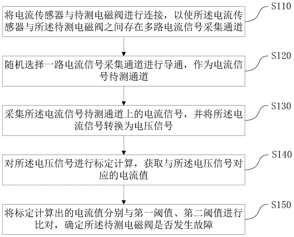
图1为本申请中一实施例提供的电磁阀电流检测方法的流程示意图;Fig. 1 is the schematic flow chart of the solenoid valve current detection method provided by an embodiment of the present application;
图2为本申请中另一实施例提供的电磁阀电流检测方法的流程示意图;FIG. 2 is a schematic flow chart of a solenoid valve current detection method provided in another embodiment of the present application;
图3为本申请中一实施例提供的电磁阀电流检测系统的硬件结构示意图;Fig. 3 is a schematic diagram of the hardware structure of the solenoid valve current detection system provided by an embodiment of the present application;
图4为本申请中一实施例提供的电磁阀电流检测系统的原理示意图;FIG. 4 is a schematic diagram of the principle of a solenoid valve current detection system provided by an embodiment of the present application;
图5为本申请中一实施例提供的电磁阀电流检测系统的硬件框架示意图。FIG. 5 is a schematic diagram of a hardware framework of a solenoid valve current detection system provided by an embodiment of the present application.
具体实施方式Detailed ways
以下通过特定的具体实例说明本申请的实施方式,本领域技术人员可由本说明书所揭露的内容轻易地了解本申请的其他优点与功效。本申请还可以通过另外不同的具体实施方式加以实施或应用,本说明书中的各项细节也可以基于不同观点与应用,在没有背离本申请的精神下进行各种修饰或改变。需说明的是,在不冲突的情况下,以下实施例及实施例中的特征可以相互组合。Embodiments of the present application are described below through specific examples, and those skilled in the art can easily understand other advantages and effects of the present application from the content disclosed in this specification. The present application can also be implemented or applied through other different specific implementation modes, and various modifications or changes can be made to the details in this specification based on different viewpoints and applications without departing from the spirit of the present application. It should be noted that, in the case of no conflict, the following embodiments and features in the embodiments can be combined with each other.
需要说明的是,本实施例中所提供的图示仅以示意方式说明本申请的基本构想,遂图式中仅显示与本申请中有关的组件而非按照实际实施时的组件数目、形状及尺寸绘制,其实际实施时各组件的型态、数量及比例可为一种随意的改变,且其组件布局型态也可能更为复杂。It should be noted that the diagrams provided in this embodiment are only schematically illustrating the basic idea of the application, and only the components related to the application are shown in the diagrams rather than the number, shape and shape of the components in actual implementation. Dimensional drawing, the type, quantity and proportion of each component can be changed arbitrarily during actual implementation, and the component layout type may also be more complicated.
请参阅图1所示,本实施例提供一种电磁阀电流检测方法,包括以下步骤:Please refer to FIG. 1, the present embodiment provides a method for detecting the current of a solenoid valve, including the following steps:
S110,将电流传感器与待测电磁阀进行连接,以使所述电流传感器与所述待测电磁阀之间存在多路电流信号采集通道;S110, connecting the current sensor to the solenoid valve to be tested, so that there are multiple current signal acquisition channels between the current sensor and the solenoid valve to be tested;
S120,随机选择一路电流信号采集通道进行导通,作为电流信号待测通道;S120, randomly selecting a current signal acquisition channel to conduct as the current signal channel to be tested;
S130,采集所述电流信号待测通道上的电流信号,并将所述电流信号转换为电压信号;S130, collect the current signal on the channel to be measured of the current signal, and convert the current signal into a voltage signal;
S140,对所述电压信号进行标定计算,获取与所述电压信号对应的电流值;S140, perform calibration calculation on the voltage signal, and obtain a current value corresponding to the voltage signal;
S150,将标定计算出的电流值分别与第一阈值、第二阈值进行比对,确定所述待测电磁阀是否发生故障;若标定计算出的电流值大于所述第一阈值,或者标定计算出的电流值小于所述第二阈值,则确定所述待测电磁阀发生故障;其中,第一阈值大于第二阈值。S150. Comparing the current value calculated by calibration with the first threshold and the second threshold, respectively, to determine whether the solenoid valve to be tested is faulty; if the current value calculated by calibration is greater than the first threshold, or the calibration calculation If the output current value is less than the second threshold, it is determined that the electromagnetic valve under test is faulty; wherein, the first threshold is greater than the second threshold.
由此可知,本实施例不需要人工巡检记录电磁阀电流检测数据,可以自动完成多路电磁阀电流数据的采集,并对异常的电流数据进行报警,提示及时检查线路并维修。相当于本实施例为电磁阀运行状态提供了一种可靠的实时监测方式,不仅节省人力时间,而且实现简单,不需要提前预装,也不需要停工停产安装,在任何时候都可以安装,只需要将传感器卡扣在电磁阀电流线上,安装简单方便,能够满足自动化控制系统中电磁阀电流检测的精度要求。同时本实施例还可以与上位机组态软件进行数据传输,将采集到的数据和判定结果通过串口通讯传送到上位机组态软件,实时监测并显示电磁阀的电流数据和运行状态。It can be seen that this embodiment does not require manual inspection and recording of solenoid valve current detection data, and can automatically complete the collection of multi-channel solenoid valve current data, and give an alarm to abnormal current data, prompting timely inspection and maintenance of the circuit. It is equivalent to that this embodiment provides a reliable real-time monitoring method for the operating state of the solenoid valve, which not only saves manpower and time, but also is simple to implement. The sensor needs to be buckled on the solenoid valve current line, the installation is simple and convenient, and it can meet the accuracy requirements of the solenoid valve current detection in the automation control system. At the same time, this embodiment can also perform data transmission with the configuration software of the host computer, and transmit the collected data and judgment results to the configuration software of the host computer through serial port communication, and monitor and display the current data and operating status of the solenoid valve in real time.
在一示例性实施例中,若所述待测电磁阀未发生故障,则本实施例还可以包括:从所述多路电流信号采集通道中选择另外一路电流信号采集通道作为新的电流信号待测通道,并基于新的电流信号待测通道上的电流信号确定所述待测电磁阀是否发生故障。由此可知,本实施例在选择一路电流信号采集通道后,如果待测电磁阀未发生故障,则会自动重新选择新的电流信号采集通道来判断待测电磁阀是否发生故障,可以自动完成多路电磁阀电流数据的采集以及对电磁阀的故障检测,从而能够满足自动化控制系统中电磁阀电流检测的精度要求。In an exemplary embodiment, if the solenoid valve to be tested does not fail, this embodiment may further include: selecting another current signal acquisition channel from the multiple current signal acquisition channels as a new current signal acquisition channel. The test channel, and based on the current signal on the test channel of the new current signal, determine whether the solenoid valve under test fails. It can be seen that in this embodiment, after selecting a current signal acquisition channel, if the solenoid valve to be tested does not fail, a new current signal acquisition channel will be automatically reselected to determine whether the solenoid valve to be tested is faulty, and multiple steps can be automatically completed. The current data collection of the solenoid valve and the fault detection of the solenoid valve can meet the accuracy requirements of the solenoid valve current detection in the automation control system.
在另一示例性实施例中,若所述待测电磁阀发生故障,则本实施例还可以包括:基于引起所述待测电磁阀发生故障的电流信号生成报警信号;其中,所述报警信号包括以下至少之一:光信号、电控制器件信号。在本实施例中,基于引起所述待测电磁阀发生故障的电流信号生成报警信号时,包括:先生成光信号,再生成电控制器件信号;或者,生成电控制器件信号,再生成光信号。作为示例,本实施例中的光信号包括:发光二级管发光信号;所述电控制器件信号包括:继电器触电信号。In another exemplary embodiment, if the electromagnetic valve to be tested fails, this embodiment may further include: generating an alarm signal based on a current signal that causes the electromagnetic valve to be tested to fail; wherein the alarm signal Including at least one of the following: optical signal, electrical control device signal. In this embodiment, when generating the alarm signal based on the current signal that causes the electromagnetic valve to be tested to fail, it includes: first generating an optical signal, and then generating an electrical control device signal; or, generating an electrical control device signal, and then generating an optical signal . As an example, the optical signal in this embodiment includes: a light-emitting diode light-emitting signal; the electrical control device signal includes: a relay electric shock signal.
在一示例性实施例中,在生成报警信号后,本实施例还可以包括:将引起所述待测电磁阀发生故障的电流信号、所述报警信号进行组装,形成数据帧;判断上位机通信串口是否存在数据帧请求;如果所述上位机通信串口存在数据帧请求,则将所述数据帧通过所述上位机通信串口发送给上位机进行实时监测,并从所述多路电流信号采集通道中选择另外一路电流信号采集通道作为新的电流信号待测通道,并基于新的电流信号待测通道上的电流信号确定所述待测电磁阀是否发生故障;如果所述上位机通信串口不存在数据帧请求,则从所述多路电流信号采集通道中选择另外一路电流信号采集通道作为新的电流信号待测通道,并基于新的电流信号待测通道上的电流信号确定所述待测电磁阀是否发生故障。由此可知,本实施例还可以通过上位机来实时监测电磁阀的电流数据和运行状态,在电磁阀出现故障时,能够及时地让维护人员进行维修。In an exemplary embodiment, after the alarm signal is generated, this embodiment may further include: assembling the current signal that causes the failure of the solenoid valve to be tested and the alarm signal to form a data frame; Whether there is a data frame request in the serial port; if there is a data frame request in the communication serial port of the upper computer, then the data frame is sent to the upper computer through the communication serial port of the upper computer for real-time monitoring, and from the multi-channel current signal acquisition channel Select another current signal acquisition channel as a new current signal channel to be tested, and determine whether the solenoid valve to be tested is faulty based on the current signal on the new current signal channel to be tested; if the host computer communication serial port does not exist data frame request, select another current signal acquisition channel from the multiple current signal acquisition channels as a new current signal channel to be tested, and determine the electromagnetic signal to be tested based on the current signal on the new current signal channel to be tested. If the valve is malfunctioning. It can be seen that, in this embodiment, the current data and operating status of the solenoid valve can be monitored in real time through the host computer, and when the solenoid valve fails, the maintenance personnel can be repaired in time.
在一示例性实施例中,本实施例还可以包括:存储在每一路电流信号采集通道上采集的电流信号以及转换后的电压信号;以及,存储与每一路电流信号采集通道所对应的电磁阀故障检测结果。In an exemplary embodiment, this embodiment may further include: storing the current signal collected on each current signal collection channel and the converted voltage signal; and storing the solenoid valve corresponding to each current signal collection channel Fault detection results.
在本申请另一示例性实施例中,如图2所示,本实施例还提供一种电磁阀电流检测方法,包括以下步骤:In another exemplary embodiment of the present application, as shown in FIG. 2 , this embodiment also provides a solenoid valve current detection method, including the following steps:
将电流传感器与待测电磁阀进行连接,以使所述电流传感器与所述待测电磁阀之间存在多路电流信号采集通道;Connecting the current sensor to the solenoid valve to be tested, so that there are multiple current signal acquisition channels between the current sensor and the solenoid valve to be tested;
随机选择一路电流信号采集通道进行导通,作为电流信号待测通道;Randomly select a current signal acquisition channel to conduct as the current signal channel to be tested;
采集所述电流信号待测通道上的电流信号,并将所述电流信号转换为电压信号;Collecting the current signal on the channel to be measured of the current signal, and converting the current signal into a voltage signal;
对所述电压信号进行标定计算,获取与所述电压信号对应的电流值;performing calibration calculation on the voltage signal to obtain a current value corresponding to the voltage signal;
将标定计算出的电流值分别与第一阈值、第二阈值进行比对,确定所述待测电磁阀是否发生故障。若基于当前选择的电流信号待测通道判断出待测电磁阀未发生故障,则从所述多路电流信号采集通道中重新选择另外一路电流信号采集通道作为新的电流信号待测通道,并基于新的电流信号待测通道上的电流信号确定所述待测电磁阀是否发生故障。若基于当前选择的电流信号待测通道判断出待测电磁阀发生故障,基于引起所述待测电磁阀发生故障的电流信号生成报警信号;即先生成发光二级管LED(Light-EmittingDiode,发光二极管,简称LED)发光信号,再生成继电器触电信号;并进入下一步;The current value calculated by calibration is compared with the first threshold value and the second threshold value respectively to determine whether the solenoid valve to be tested is faulty. If it is judged that the electromagnetic valve to be tested has not broken down based on the currently selected current signal channel to be tested, then reselect another current signal acquisition channel as a new current signal channel to be tested from the multiple current signal acquisition channels, and based on The current signal on the channel under test of the new current signal determines whether the solenoid valve under test fails. If it is judged that the solenoid valve to be tested fails based on the currently selected current signal channel to be tested, an alarm signal is generated based on the current signal that causes the solenoid valve to be tested to fail; Diode, referred to as LED) light-emitting signal, and then generate a relay electric shock signal; and enter the next step;
将引起所述待测电磁阀发生故障的电流信号、所述报警信号进行组装,形成数据帧;Assembling the current signal and the alarm signal causing the failure of the solenoid valve to be tested to form a data frame;
判断上位机通信串口是否存在数据帧请求;如果所述上位机通信串口存在数据帧请求,则将所述数据帧通过所述上位机通信串口发送给上位机进行实时监测,并从所述多路电流信号采集通道中选择另外一路电流信号采集通道作为新的电流信号待测通道,并基于新的电流信号待测通道上的电流信号确定所述待测电磁阀是否发生故障;如果所述上位机通信串口不存在数据帧请求,则从所述多路电流信号采集通道中选择另外一路电流信号采集通道作为新的电流信号待测通道,并基于新的电流信号待测通道上的电流信号确定所述待测电磁阀是否发生故障。Judge whether there is a data frame request at the communication serial port of the upper computer; if there is a data frame request at the communication serial port of the upper computer, then the data frame is sent to the upper computer through the communication serial port of the upper computer for real-time monitoring, and from the multi-channel Select another current signal acquisition channel in the current signal acquisition channel as a new current signal channel to be tested, and determine whether the solenoid valve to be tested is faulty based on the current signal on the new current signal channel to be tested; if the host computer If there is no data frame request at the communication serial port, another current signal acquisition channel is selected from the multiple current signal acquisition channels as a new current signal channel to be tested, and the current signal on the new current signal channel to be tested is used to determine the current signal. Check whether the solenoid valve to be tested is faulty.
由此可知,本实施例不需要人工巡检记录电磁阀电流检测数据,可以自动完成多路电磁阀电流数据的采集,并对异常的电流数据进行报警,提示及时检查线路并维修。相当于本实施例为电磁阀运行状态提供了一种可靠的实时监测方式,不仅节省人力时间,而且实现简单,不需要提前预装,也不需要停工停产安装,在任何时候都可以安装,只需要将传感器卡扣在电磁阀电流线上,安装简单方便,能够满足自动化控制系统中电磁阀电流检测的精度要求。同时本实施例还可以与上位机组态软件进行数据传输,将采集到的数据和判定结果通过串口通讯传送到上位机组态软件,实时监测并显示电磁阀的电流数据和运行状态。It can be seen that this embodiment does not require manual inspection and recording of solenoid valve current detection data, and can automatically complete the collection of multi-channel solenoid valve current data, and give an alarm to abnormal current data, prompting timely inspection and maintenance of the circuit. It is equivalent to that this embodiment provides a reliable real-time monitoring method for the operating state of the solenoid valve, which not only saves manpower and time, but also is simple to implement. The sensor needs to be buckled on the solenoid valve current line, the installation is simple and convenient, and it can meet the accuracy requirements of the solenoid valve current detection in the automation control system. At the same time, this embodiment can also perform data transmission with the configuration software of the host computer, and transmit the collected data and judgment results to the configuration software of the host computer through serial port communication, and monitor and display the current data and operating status of the solenoid valve in real time.
综上所述,本申请提供一种电磁阀电流检测方法,首先将电流传感器与待测电磁阀进行连接,以使所述电流传感器与所述待测电磁阀之间存在多路电流信号采集通道;然后随机选择一路电流信号采集通道进行导通,作为电流信号待测通道;再采集所述电流信号待测通道上的电流信号,并将所述电流信号转换为电压信号;再对所述电压信号进行标定计算,获取与所述电压信号对应的电流值;最后将标定计算出的电流值分别与第一阈值、第二阈值进行比对,确定所述待测电磁阀是否发生故障;若标定计算出的电流值大于所述第一阈值,或者标定计算出的电流值小于所述第二阈值,则确定所述待测电磁阀发生故障;其中,第一阈值大于第二阈值。由此可知,本方法不需要人工巡检记录电磁阀电流检测数据,可以自动完成多路电磁阀电流数据的采集,并对异常的电流数据进行报警,提示及时检查线路并维修。相当于本方法为电磁阀运行状态提供了一种可靠的实时监测方式,不仅节省人力时间,而且实现简单,不需要提前预装,也不需要停工停产安装,在任何时候都可以安装,只需要将传感器卡扣在电磁阀电流线上,安装简单方便,能够满足自动化控制系统中电磁阀电流检测的精度要求。同时本方法还可以与上位机组态软件进行数据传输,将采集到的数据和判定结果通过串口通讯传送到上位机组态软件,实时监测并显示电磁阀的电流数据和运行状态。In summary, the present application provides a method for detecting the current of a solenoid valve. Firstly, the current sensor is connected to the solenoid valve to be tested, so that there are multiple current signal acquisition channels between the current sensor and the solenoid valve to be tested. ; Then randomly select one current signal acquisition channel to be turned on as the current signal channel to be measured; then collect the current signal on the channel to be measured of the current signal, and convert the current signal into a voltage signal; The signal is calibrated and calculated to obtain the current value corresponding to the voltage signal; finally, the current value calculated by the calibration is compared with the first threshold and the second threshold respectively to determine whether the electromagnetic valve to be tested is faulty; if the calibration If the calculated current value is greater than the first threshold, or if the calculated current value is less than the second threshold, then it is determined that the electromagnetic valve under test is faulty; wherein the first threshold is greater than the second threshold. It can be seen that this method does not require manual inspection to record the current detection data of the solenoid valve, and can automatically complete the collection of multi-channel solenoid valve current data, and alarm the abnormal current data, prompting timely inspection and maintenance of the circuit. It is equivalent to that this method provides a reliable real-time monitoring method for the operating state of the solenoid valve, which not only saves manpower and time, but also is simple to implement. The sensor is buckled on the current line of the solenoid valve, which is simple and convenient to install, and can meet the accuracy requirements of the solenoid valve current detection in the automatic control system. At the same time, the method can also perform data transmission with the configuration software of the host computer, and transmit the collected data and judgment results to the configuration software of the host computer through serial port communication, and monitor and display the current data and operating status of the solenoid valve in real time.
如图3所示,本申请还提供一种电磁阀电流检测系统,所述系统包括有:As shown in Figure 3, the present application also provides a solenoid valve current detection system, the system includes:
通讯模块310,用于将电流传感器与待测电磁阀进行连接,以使所述电流传感器与所述待测电磁阀之间存在多路电流信号采集通道。作为示例,本实施例中的通讯模块310可以以STM32F107芯片为核心控制器,然后连接设置16路电流信号采集通道。The
通道选择模块320,用于随机选择一路电流信号采集通道进行导通,作为电流信号待测通道。作为示例,本实施例中的通道选择模块320可以由STM32F107芯片为核心控制器进行通道选择,也可以由STM32F107芯片的外围电路来进行通道选择。The
电流转换模块330,用于采集所述电流信号待测通道上的电流信号,并将所述电流信号转换为电压信号。作为示例,本实施例中的电流转换模块330可以由电流转换电路和电流传感器电路组成。The
标定计算模块340,用于对所述电压信号进行标定计算,获取与所述电压信号对应的电流值。作为示例,本实施例中的标定计算模块340可以由STM32F107芯片为核心控制器来完成标定计算,也可以由STM32F107芯片的外围电路来来完成标定计算。The
故障检测模块350,用于将标定计算出的电流值分别与第一阈值、第二阈值进行比对,确定所述待测电磁阀是否发生故障;若标定计算出的电流值大于所述第一阈值,或者标定计算出的电流值小于所述第二阈值,则确定所述待测电磁阀发生故障;其中,第一阈值大于第二阈值。The
由此可知,本实施例不需要人工巡检记录电磁阀电流检测数据,可以自动完成多路电磁阀电流数据的采集,并对异常的电流数据进行报警,提示及时检查线路并维修。相当于本实施例为电磁阀运行状态提供了一种可靠的实时监测方式,不仅节省人力时间,而且实现简单,不需要提前预装,也不需要停工停产安装,在任何时候都可以安装,只需要将传感器卡扣在电磁阀电流线上,安装简单方便,能够满足自动化控制系统中电磁阀电流检测的精度要求。同时本实施例还可以与上位机组态软件进行数据传输,将采集到的数据和判定结果通过串口通讯传送到上位机组态软件,实时监测并显示电磁阀的电流数据和运行状态。It can be seen that this embodiment does not require manual inspection and recording of solenoid valve current detection data, and can automatically complete the collection of multi-channel solenoid valve current data, and give an alarm to abnormal current data, prompting timely inspection and maintenance of the circuit. It is equivalent to that this embodiment provides a reliable real-time monitoring method for the operating state of the solenoid valve, which not only saves manpower and time, but also is simple to implement. The sensor needs to be buckled on the solenoid valve current line, the installation is simple and convenient, and it can meet the accuracy requirements of the solenoid valve current detection in the automation control system. At the same time, this embodiment can also perform data transmission with the configuration software of the host computer, and transmit the collected data and judgment results to the configuration software of the host computer through serial port communication, and monitor and display the current data and operating status of the solenoid valve in real time.
在一示例性实施例中,所述电磁阀电流检测系统还可以包括报警模块,用于在所述待测电磁阀发生故障时,基于引起所述待测电磁阀发生故障的电流信号生成报警信号;其中,所述报警信号包括以下至少之一:光信号、电控制器件信号。在本实施例中,报警模块可以由LED和继电器组成,例如由LED光报警电路和继电器触电电路组成。作为示例,基于引起所述待测电磁阀发生故障的电流信号生成报警信号时,包括:先生成光信号,再生成电控制器件信号;或者,生成电控制器件信号,再生成光信号。即本实施例中的光信号可以为发光二级管发光信号;所述电控制器件信号可以为继电器触电信号。In an exemplary embodiment, the solenoid valve current detection system may further include an alarm module, configured to generate an alarm signal based on a current signal that causes the solenoid valve to be tested to fail when the solenoid valve to be tested fails ; Wherein, the alarm signal includes at least one of the following: optical signal, electrical control device signal. In this embodiment, the alarm module may be composed of LEDs and relays, for example, an LED light alarm circuit and a relay electric shock circuit. As an example, when generating the alarm signal based on the current signal that causes the electromagnetic valve to be tested to fail, it includes: generating an optical signal first, and then generating an electrical control device signal; or generating an electrical control device signal, and then generating an optical signal. That is, the optical signal in this embodiment may be a light-emitting diode light-emitting signal; the electrical control device signal may be a relay electric shock signal.
在一示例性实施例中,在生成报警信号后,本实施例还可以包括:将引起所述待测电磁阀发生故障的电流信号、所述报警信号进行组装,形成数据帧;判断上位机通信串口是否存在数据帧请求;如果所述上位机通信串口存在数据帧请求,则将所述数据帧通过所述上位机通信串口发送给上位机进行实时监测,并从所述多路电流信号采集通道中选择另外一路电流信号采集通道作为新的电流信号待测通道,并基于新的电流信号待测通道上的电流信号确定所述待测电磁阀是否发生故障;如果所述上位机通信串口不存在数据帧请求,则从所述多路电流信号采集通道中选择另外一路电流信号采集通道作为新的电流信号待测通道,并基于新的电流信号待测通道上的电流信号确定所述待测电磁阀是否发生故障。由此可知,本实施例还可以通过上位机来实时监测电磁阀的电流数据和运行状态,在电磁阀出现故障时,能够及时地让维护人员进行维修。作为示例,本实施例中的上位机通信串口可以是RS485通讯串口。In an exemplary embodiment, after the alarm signal is generated, this embodiment may further include: assembling the current signal that causes the failure of the solenoid valve to be tested and the alarm signal to form a data frame; Whether there is a data frame request in the serial port; if there is a data frame request in the communication serial port of the upper computer, then the data frame is sent to the upper computer through the communication serial port of the upper computer for real-time monitoring, and from the multi-channel current signal acquisition channel Select another current signal acquisition channel as a new current signal channel to be tested, and determine whether the solenoid valve to be tested is faulty based on the current signal on the new current signal channel to be tested; if the host computer communication serial port does not exist data frame request, select another current signal acquisition channel from the multiple current signal acquisition channels as a new current signal channel to be tested, and determine the electromagnetic signal to be tested based on the current signal on the new current signal channel to be tested. Whether the valve is malfunctioning. It can be seen that, in this embodiment, the current data and operating status of the solenoid valve can be monitored in real time through the host computer, and when the solenoid valve fails, the maintenance personnel can be repaired in time. As an example, the host computer communication serial port in this embodiment may be an RS485 communication serial port.
在一示例性实施例中,所述电磁阀电流检测系统还可以包括存储模块,用于存储在每一路电流信号采集通道上采集的电流信号以及转换后的电压信号;以及,存储与每一路电流信号采集通道所对应的电磁阀故障检测结果。作为示例,本实施例中的存储模块可以由EEPROM存储器组成,也可以由EEPROM存储器及其关联电路组成。In an exemplary embodiment, the solenoid valve current detection system may further include a storage module for storing the current signal and the converted voltage signal collected on each current signal acquisition channel; The solenoid valve failure detection result corresponding to the signal acquisition channel. As an example, the storage module in this embodiment may be composed of an EEPROM memory, or may be composed of an EEPROM memory and its associated circuits.
在本申请另一示例性实施例中,如图4和图5所示,该实施例还提供一种电磁阀电流检测系统,包括有:STM32核心控制模块、传感器模块、报警模块、通讯模块、存储模块和继电器输出模块。STM32核心控制模块实现数据的采集、处理、运算,是整个电流诊断的核心部件。传感器模块主要指外购的电流传感器以及电流转电压的转换模块。报警模块主要用于判断在断路或过流时发出光报警信号,光报警主要用LED指示灯显示。通讯模块使用的是RS485,使用MODBUS RTU模式通信协议,与外部通讯设备传输电流大小及报警数据信息。存储器模块主要用数据存储。继电器输出模块主要用于触电输出。在图4中,电流信号就是待检测的电磁阀电流信号,电流传感器是依据电磁感应原理将一次侧大电流转换成二次侧小电流来测量的仪器,转换模块是将电流信号转换为电压信号。STM32控制模块对采集到传感器数据进行计算分析,将最终的数据和判定结果传送到上位机组态软件显示,系统还可以根据现场应用要求,判断在断路或过流时发出报警信号,从而能及时让维护人员进行维修。In another exemplary embodiment of the present application, as shown in Figure 4 and Figure 5, this embodiment also provides a solenoid valve current detection system, including: STM32 core control module, sensor module, alarm module, communication module, Storage modules and relay output modules. The STM32 core control module realizes data collection, processing, and calculation, and is the core component of the entire current diagnosis. Sensor modules mainly refer to outsourced current sensors and current-to-voltage conversion modules. The alarm module is mainly used to judge the light alarm signal when the circuit is broken or over-current, and the light alarm is mainly displayed by the LED indicator. The communication module uses RS485, uses MODBUS RTU mode communication protocol, and transmits current magnitude and alarm data information with external communication equipment. The memory module is mainly used for data storage. The relay output module is mainly used for electric shock output. In Figure 4, the current signal is the current signal of the solenoid valve to be detected. The current sensor is an instrument that converts a large current on the primary side into a small current on the secondary side for measurement based on the principle of electromagnetic induction. The conversion module converts the current signal into a voltage signal. . The STM32 control module calculates and analyzes the collected sensor data, and transmits the final data and judgment results to the configuration software of the upper computer for display. Have maintenance personnel repair it.
在图5中,本系统选用STM32F107芯片作为核心控制器,共设置了16路电流信号采集通道,STM32控制模块通过内部ADC对转换的电压信号进行采样,并将采集数据按照标定的数学转换关系进行电流值计算,对电流值按照内置的阈值进行判定,根据判定结果进行LED光报警。在数据通信方面,系统设计了统一的MODBUS通信协议,上位机组态软件通过RS485总线,完成指令的下发和数据的接收,实现电磁阀电流数据的实时监测。In Figure 5, the system uses the STM32F107 chip as the core controller, and a total of 16 current signal acquisition channels are set up. The STM32 control module samples the converted voltage signal through the internal ADC, and the collected data is converted according to the calibrated mathematical conversion relationship. The current value is calculated, and the current value is judged according to the built-in threshold value, and the LED light alarm is issued according to the judgment result. In terms of data communication, the system has designed a unified MODBUS communication protocol. The upper computer configuration software completes the sending of instructions and receiving data through the RS485 bus to realize real-time monitoring of solenoid valve current data.
本实施例的软件设计主要包括主程序设计、电流传感器数据采集程序设计、报警判定程序设计、以及RS485通信程序设计。主程序运行流程图如图2所示,在系统上电后,MCU先完成系统时钟、IO口线、ADC、串口以及EEPROM数据读取等初始化工作。初始化完成之后,选择接通一路电流传感器,进行电压信号的采集,MCU将采集数据按照标定的数学转换关系进行电流值计算,并对电流值按照设置的阈值进行判定,根据判定结果进行LED光报警和继电器触电输出报警,同时将电流信号数据和报警数据传送给上位机组态软件显示。The software design of this embodiment mainly includes main program design, current sensor data acquisition program design, alarm judgment program design, and RS485 communication program design. The flow chart of the main program is shown in Figure 2. After the system is powered on, the MCU first completes the initialization of the system clock, IO line, ADC, serial port, and EEPROM data reading. After the initialization is completed, choose to connect a current sensor to collect the voltage signal. The MCU will calculate the current value according to the calibrated mathematical conversion relationship of the collected data, and judge the current value according to the set threshold value, and issue an LED light alarm according to the judgment result. And relay electric shock output alarm, at the same time, the current signal data and alarm data are transmitted to the upper computer configuration software for display.
综上所述,本申请提供一种电磁阀电流检测系统,首先将电流传感器与待测电磁阀进行连接,以使所述电流传感器与所述待测电磁阀之间存在多路电流信号采集通道;然后随机选择一路电流信号采集通道进行导通,作为电流信号待测通道;再采集所述电流信号待测通道上的电流信号,并将所述电流信号转换为电压信号;再对所述电压信号进行标定计算,获取与所述电压信号对应的电流值;最后将标定计算出的电流值分别与第一阈值、第二阈值进行比对,确定所述待测电磁阀是否发生故障;若标定计算出的电流值大于所述第一阈值,或者标定计算出的电流值小于所述第二阈值,则确定所述待测电磁阀发生故障;其中,第一阈值大于第二阈值。由此可知,本系统不需要人工巡检记录电磁阀电流检测数据,可以自动完成多路电磁阀电流数据的采集,并对异常的电流数据进行报警,提示及时检查线路并维修。相当于本系统为电磁阀运行状态提供了一种可靠的实时监测方式,不仅节省人力时间,而且实现简单,不需要提前预装,也不需要停工停产安装,在任何时候都可以安装,只需要将传感器卡扣在电磁阀电流线上,安装简单方便,能够满足自动化控制系统中电磁阀电流检测的精度要求。同时本系统还可以与上位机组态软件进行数据传输,将采集到的数据和判定结果通过串口通讯传送到上位机组态软件,实时监测并显示电磁阀的电流数据和运行状态。To sum up, the present application provides a solenoid valve current detection system. First, the current sensor is connected to the solenoid valve to be tested, so that there are multiple current signal acquisition channels between the current sensor and the solenoid valve to be tested. ; Then randomly select one current signal acquisition channel to be turned on as the current signal channel to be measured; then collect the current signal on the channel to be measured of the current signal, and convert the current signal into a voltage signal; The signal is calibrated and calculated to obtain the current value corresponding to the voltage signal; finally, the current value calculated by the calibration is compared with the first threshold and the second threshold respectively to determine whether the electromagnetic valve to be tested is faulty; if the calibration If the calculated current value is greater than the first threshold, or if the calculated current value is less than the second threshold, then it is determined that the electromagnetic valve under test is faulty; wherein the first threshold is greater than the second threshold. It can be seen that this system does not need manual inspection to record the current detection data of the solenoid valve, and can automatically complete the collection of multi-channel solenoid valve current data, and alarm the abnormal current data, prompting timely inspection and maintenance of the line. It is equivalent to that this system provides a reliable real-time monitoring method for the operating status of the solenoid valve, which not only saves manpower and time, but also is simple to implement. The sensor is buckled on the current line of the solenoid valve, which is simple and convenient to install, and can meet the accuracy requirements of the solenoid valve current detection in the automatic control system. At the same time, this system can also carry out data transmission with the configuration software of the upper computer, and transmit the collected data and judgment results to the configuration software of the upper computer through serial port communication, and monitor and display the current data and operating status of the solenoid valve in real time.
需要说明的是,上述实施例所提供电磁阀电流检测系统与上述实施例所提供的电磁阀电流检测方法属于同一构思,其中各个模块和单元执行操作的具体方式已经在方法实施例中进行了详细描述,此处不再赘述。上述实施例所提供的电磁阀电流检测系统在实际应用中,可以根据需要而将上述功能分配由不同的功能模块完成,即将系统的内部结构划分成不同的功能模块,以完成以上描述的全部或者部分功能,此处不进行限制。所以,本申请有效克服了现有技术中的种种缺点而具高度产业利用价值。It should be noted that the solenoid valve current detection system provided in the above embodiment and the solenoid valve current detection method provided in the above embodiment belong to the same concept, and the specific operation methods of each module and unit have been described in detail in the method embodiment. description and will not be repeated here. In the actual application of the electromagnetic valve current detection system provided by the above embodiments, the above function distribution can be completed by different functional modules according to the needs, that is, the internal structure of the system is divided into different functional modules, so as to complete all or all of the above descriptions. Some functions are not limited here. Therefore, the present application effectively overcomes various shortcomings in the prior art and has high industrial application value.
上述实施例仅例示性说明本申请的原理及其功效,而非用于限制本申请。任何熟悉此技术的人士皆可在不违背本申请的精神及范畴下,对上述实施例进行修饰或改变。因此,举凡所属技术领域中具有通常知识者在未脱离本申请所揭示的精神与技术思想下所完成的一切等效修饰或改变,仍应由本申请的权利要求所涵盖。The above-mentioned embodiments are only illustrative to illustrate the principles and effects of the present application, but are not intended to limit the present application. Any person familiar with the technology can modify or change the above-mentioned embodiments without departing from the spirit and scope of the present application. Therefore, all equivalent modifications or changes made by those skilled in the art without departing from the spirit and technical ideas disclosed in the application shall still be covered by the claims of the application.
应当理解的是,尽管在本申请实施例中可能采用术语第一、第二、第三等来描述预设范围等,但这些预设范围不应限于这些术语。这些术语仅用来将预设范围彼此区分开。例如,在不脱离本申请实施例范围的情况下,第一预设范围也可以被称为第二预设范围,类似地,第二预设范围也可以被称为第一预设范围。It should be understood that although the terms first, second, third, etc. may be used in the embodiments of the present application to describe preset ranges, etc., these preset ranges should not be limited to these terms. These terms are only used to distinguish preset ranges from one another. For example, without departing from the scope of the embodiments of the present application, the first preset range may also be called the second preset range, and similarly, the second preset range may also be called the first preset range.
Claims (10)
Priority Applications (1)
| Application Number | Priority Date | Filing Date | Title |
|---|---|---|---|
| CN202310103555.8A CN116338290A (en) | 2023-02-10 | 2023-02-10 | A solenoid valve current detection method and system |
Applications Claiming Priority (1)
| Application Number | Priority Date | Filing Date | Title |
|---|---|---|---|
| CN202310103555.8A CN116338290A (en) | 2023-02-10 | 2023-02-10 | A solenoid valve current detection method and system |
Publications (1)
| Publication Number | Publication Date |
|---|---|
| CN116338290A true CN116338290A (en) | 2023-06-27 |
Family
ID=86892022
Family Applications (1)
| Application Number | Title | Priority Date | Filing Date |
|---|---|---|---|
| CN202310103555.8A Pending CN116338290A (en) | 2023-02-10 | 2023-02-10 | A solenoid valve current detection method and system |
Country Status (1)
| Country | Link |
|---|---|
| CN (1) | CN116338290A (en) |
Cited By (3)
| Publication number | Priority date | Publication date | Assignee | Title |
|---|---|---|---|---|
| CN119611060A (en) * | 2024-12-06 | 2025-03-14 | 中国第一汽车股份有限公司 | Current abnormality monitoring device, monitoring method and vehicle |
| CN120103123A (en) * | 2023-12-06 | 2025-06-06 | 中国石油化工股份有限公司 | A multi-channel solenoid valve fault detection device and method |
| CN119611060B (en) * | 2024-12-06 | 2026-05-15 | 中国第一汽车股份有限公司 | Current abnormality monitoring device, monitoring method and vehicle |
Citations (7)
| Publication number | Priority date | Publication date | Assignee | Title |
|---|---|---|---|---|
| JP2002174358A (en) * | 2000-12-08 | 2002-06-21 | Smc Corp | Solenoid valve with failure diagnostic function |
| CN109031088A (en) * | 2018-06-11 | 2018-12-18 | 成都京蓉伟业电子有限公司 | A kind of circuit board multichannel current test method and its system |
| CN110208624A (en) * | 2019-06-19 | 2019-09-06 | 河南辉煌科技股份有限公司 | A kind of humping signal equipment on-line monitoring system and retarder on-line monitoring method |
| CN111399368A (en) * | 2020-03-26 | 2020-07-10 | 电子科技大学 | A Redundancy Technology of Multi-channel Solenoid Valve Drive System |
| CN111610440A (en) * | 2020-05-13 | 2020-09-01 | 石家庄君乐宝乳业有限公司 | Solenoid valve fault detection circuit and detection method |
| CN113702684A (en) * | 2021-08-30 | 2021-11-26 | 常州苏度科技有限公司 | Multichannel current measurement system based on shunt |
| CN114941642A (en) * | 2022-03-25 | 2022-08-26 | 阳江核电有限公司 | Method and system for detecting abnormal current characteristics of hydraulic solenoid valve |
-
2023
- 2023-02-10 CN CN202310103555.8A patent/CN116338290A/en active Pending
Patent Citations (7)
| Publication number | Priority date | Publication date | Assignee | Title |
|---|---|---|---|---|
| JP2002174358A (en) * | 2000-12-08 | 2002-06-21 | Smc Corp | Solenoid valve with failure diagnostic function |
| CN109031088A (en) * | 2018-06-11 | 2018-12-18 | 成都京蓉伟业电子有限公司 | A kind of circuit board multichannel current test method and its system |
| CN110208624A (en) * | 2019-06-19 | 2019-09-06 | 河南辉煌科技股份有限公司 | A kind of humping signal equipment on-line monitoring system and retarder on-line monitoring method |
| CN111399368A (en) * | 2020-03-26 | 2020-07-10 | 电子科技大学 | A Redundancy Technology of Multi-channel Solenoid Valve Drive System |
| CN111610440A (en) * | 2020-05-13 | 2020-09-01 | 石家庄君乐宝乳业有限公司 | Solenoid valve fault detection circuit and detection method |
| CN113702684A (en) * | 2021-08-30 | 2021-11-26 | 常州苏度科技有限公司 | Multichannel current measurement system based on shunt |
| CN114941642A (en) * | 2022-03-25 | 2022-08-26 | 阳江核电有限公司 | Method and system for detecting abnormal current characteristics of hydraulic solenoid valve |
Cited By (3)
| Publication number | Priority date | Publication date | Assignee | Title |
|---|---|---|---|---|
| CN120103123A (en) * | 2023-12-06 | 2025-06-06 | 中国石油化工股份有限公司 | A multi-channel solenoid valve fault detection device and method |
| CN119611060A (en) * | 2024-12-06 | 2025-03-14 | 中国第一汽车股份有限公司 | Current abnormality monitoring device, monitoring method and vehicle |
| CN119611060B (en) * | 2024-12-06 | 2026-05-15 | 中国第一汽车股份有限公司 | Current abnormality monitoring device, monitoring method and vehicle |
Similar Documents
| Publication | Publication Date | Title |
|---|---|---|
| CN112683521B (en) | On-line Monitoring and Fault Diagnosis System of Electric Valve Status in Nuclear Power Plant | |
| CN115313649B (en) | Intelligent substation process layer network broken link fault analysis device | |
| EP3444944B1 (en) | Fault detection and positioning system for cell panel in large-scale photovoltaic array | |
| CN101207280B (en) | Power system relay protection intelligent calibration method and device | |
| CN103472331B (en) | A kind of photovoltaic generation fault diagnosis system based on photovoltaic physical model | |
| CN117118808B (en) | Multi-source ammeter data acquisition and analysis method, system and storage medium based on Internet of things | |
| CN102353927A (en) | Filed tester for acquisition system for electricity consumption information and test method thereof | |
| CN109687905A (en) | A kind of intelligent substation communication link abnormal state detection system | |
| CN104090252A (en) | Comprehensive detecting system and method for cable type fault indicator | |
| CN102998027A (en) | Transformer temperature check and test device and method for checking faults of temperature control system | |
| CN115729217A (en) | Test system for controlling full link of thyristor converter valve | |
| CN107783073A (en) | Electric Energy Tariff Point Metering Device operation management system, data acquisition and alarm method | |
| CN101763097B (en) | Quality flow controller/ageing measurement monitoring system | |
| CN107167181A (en) | The intelligent automation detection method and system of a kind of electric heater | |
| CN106569165A (en) | Remote online detection system for metering performance of electronic electric energy meter | |
| CN115144782B (en) | Card aging status analysis method, system, computer product and storage medium | |
| CN109818335B (en) | Protection system abnormal event diagnosis system and method based on fault tree analysis | |
| CN116153036A (en) | An intelligent inspection and alarm system and method for a hydropower station | |
| CN101710677A (en) | Method for indicating equipment failure in cabinet | |
| CN114137945A (en) | Integrated detection device of wind-operated cabinet | |
| CN213750199U (en) | Remote monitoring and maintaining system of chip testing machine | |
| CN207557362U (en) | A kind of full production cycle automatic test device of distribution terminal | |
| CN116760191A (en) | Electric load debugging method and device | |
| CN202204925U (en) | On-site tester for electricity consumption information collection system | |
| CN206311203U (en) | Vibration monitor system integrated meter |
Legal Events
| Date | Code | Title | Description |
|---|---|---|---|
| PB01 | Publication | ||
| PB01 | Publication | ||
| SE01 | Entry into force of request for substantive examination | ||
| SE01 | Entry into force of request for substantive examination |