CN116335466A - Automatic pole holding device and splicing method suitable for automatic disassembly and assembly on construction sites - Google Patents
Automatic pole holding device and splicing method suitable for automatic disassembly and assembly on construction sites Download PDFInfo
- Publication number
- CN116335466A CN116335466A CN202310439727.9A CN202310439727A CN116335466A CN 116335466 A CN116335466 A CN 116335466A CN 202310439727 A CN202310439727 A CN 202310439727A CN 116335466 A CN116335466 A CN 116335466A
- Authority
- CN
- China
- Prior art keywords
- pole
- holding
- groove
- section
- automatic
- Prior art date
- Legal status (The legal status is an assumption and is not a legal conclusion. Google has not performed a legal analysis and makes no representation as to the accuracy of the status listed.)
- Granted
Links
Images
Classifications
-
- E—FIXED CONSTRUCTIONS
- E04—BUILDING
- E04H—BUILDINGS OR LIKE STRUCTURES FOR PARTICULAR PURPOSES; SWIMMING OR SPLASH BATHS OR POOLS; MASTS; FENCING; TENTS OR CANOPIES, IN GENERAL
- E04H12/00—Towers; Masts or poles; Chimney stacks; Water-towers; Methods of erecting such structures
- E04H12/34—Arrangements for erecting or lowering towers, masts, poles, chimney stacks, or the like
- E04H12/342—Arrangements for stacking tower sections on top of each other
Landscapes
- Engineering & Computer Science (AREA)
- Architecture (AREA)
- Civil Engineering (AREA)
- Structural Engineering (AREA)
- Manufacture Of Motors, Generators (AREA)
Abstract
Description
技术领域technical field
本发明涉及抱杆装置领域,尤其涉及一种适用于施工场地自动拆装的自动化抱杆装置,本发明同时公开了该自动化抱杆装置的拼接方法。The invention relates to the field of pole-holding devices, in particular to an automatic pole-holding device suitable for automatic disassembly and assembly on construction sites. The invention also discloses a splicing method for the automatic pole-holding device.
背景技术Background technique
在输电线路施工工程中,会需要建设大量的高压铁塔等,而高压铁塔一般是由若干不同类型的建材组装而成,现有的高压铁塔的搭建流程一般为,先在地面建好基础和塔脚,然后逐步向上组装塔身建材,当高压铁塔架设到一定高度时,需要借助抱杆装置作为辅助的吊装工具,将各建材安全的运送到架设的高度位置上。In the construction of transmission lines, it is necessary to build a large number of high-voltage iron towers, etc., and high-voltage iron towers are generally assembled from several different types of building materials. The existing high-voltage iron towers are generally constructed. feet, and then gradually assemble the building materials of the tower body upwards. When the high-voltage iron tower is erected to a certain height, it is necessary to use the pole holding device as an auxiliary lifting tool to safely transport the building materials to the erected height position.
在抱杆装置使用的过程中,随着高压铁塔的搭建高度越来越高,抱杆装置的高度也需要不断增加,以保证将建材吊起至组装位置上,而上述类型的抱杆装置在增加抱杆分段时,两个抱杆段之间需要通过多个连接机构进行组装固定,由于连接机构的数量较多,在整个搭建过程中需要重复多次增高,另外在高压铁塔建设完成之后,又需要借助外部的工具和设备一一将组装的抱杆分段拆卸下来,因此,整个组装和拆卸过程中操作难度较大,工作负担较为繁重,自动化程度较低,不便于进行拆装。During the use of the pole-holding device, as the height of the high-voltage iron tower is getting higher and higher, the height of the pole-holding device also needs to be continuously increased to ensure that the building materials are hoisted to the assembly position, and the above-mentioned type of pole-holding device is in When adding pole-holding sections, multiple connecting mechanisms need to be used to assemble and fix the two pole-holding sections. Due to the large number of connecting mechanisms, it is necessary to repeat the height increase many times during the entire construction process. In addition, after the construction of the high-voltage iron tower is completed , It is necessary to disassemble the assembled poles one by one with the help of external tools and equipment. Therefore, the entire assembly and disassembly process is difficult to operate, the workload is relatively heavy, the degree of automation is low, and it is not easy to disassemble.
发明内容Contents of the invention
本发明的目的是为了解决现有技术中存在的缺点,而提出的一种适用于施工场地自动拆装的自动化抱杆装置。The purpose of the present invention is to solve the shortcomings in the prior art, and propose an automatic pole holding device suitable for automatic disassembly and assembly on construction sites.
为达到以上目的,本发明采用的技术方案为:一种适用于施工场地自动拆装的自动化抱杆装置,包括:底座、抱杆顶段和抱杆拼接段,所述底座的顶部固定安装有稳定支架,所述稳定支架的顶部贯通开设有滑动槽,所述抱杆顶段的底端由所述稳定支架的顶部滑动延伸至所述滑动槽内,所述抱杆顶段的底端与所述抱杆拼接段的底端均开设有螺纹槽,所述抱杆拼接段的顶端固定安装有用于与所述螺纹槽适配的螺纹柱;In order to achieve the above purpose, the technical solution adopted by the present invention is: an automatic pole holding device suitable for automatic disassembly and assembly on the construction site, including: a base, a pole top section and a pole splicing section, and the top of the base is fixedly installed with A stable bracket, the top of the stable bracket is provided with a sliding groove, the bottom end of the top section of the pole is slid from the top of the stable bracket and extends into the sliding groove, the bottom end of the top section of the pole is connected to the The bottom ends of the pole-holding splicing sections are provided with thread grooves, and the top ends of the pole-holding splicing sections are fixedly installed with threaded posts for matching with the thread grooves;
所述稳定支架的内部安装有主动提升机构;An active lifting mechanism is installed inside the stabilizing bracket;
所述底座上设置有用于驱动所述抱杆拼接段自动与所述抱杆顶段旋紧的旋紧机构,所述抱杆拼接段的底端与所述旋紧机构活动卡接,所述旋紧机构包括转筒和用于驱动所述转筒转动的驱动部件,所述转筒的内部设置有用于对所述抱杆拼接段底端进行夹持和抬升的升降部件。The base is provided with a tightening mechanism for driving the splicing section of the pole to automatically tighten with the top section of the pole, the bottom end of the splicing section of the pole is movably engaged with the tightening mechanism, the The tightening mechanism includes a rotating drum and a driving part for driving the rotating drum to rotate, and a lifting part for clamping and lifting the bottom end of the pole splicing section is arranged inside the rotating drum.
优选的,所述底座的顶部开设有装置槽,所述转筒的底端与所述装置槽的底壁转动连接,所述转筒的顶端由所述装置槽内转动贯穿出所述底座的顶部。Preferably, a device groove is provided on the top of the base, the bottom end of the drum is rotatably connected to the bottom wall of the device groove, and the top of the drum rotates through the device groove and passes through the bottom of the base. top.
优选的,所述驱动部件包括驱动电机和齿环,所述驱动电机固定安装在所述装置槽的底壁上,所述齿环固定套装在所述转筒的底端,所述驱动电机的输出端固定安装有与所述齿环啮合的第一齿轮。Preferably, the drive component includes a drive motor and a gear ring, the drive motor is fixedly mounted on the bottom wall of the device groove, the gear ring is fixedly sleeved on the bottom end of the drum, and the drive motor The output end is fixedly installed with a first gear meshing with the gear ring.
优选的,所述升降部件包括固定安装在所述转筒底壁的液压缸,所述液压缸的伸缩端固定安装有与所述转筒内壁滑动连接的滑动夹座,所述滑动夹座的顶部开设有用于放置所述抱杆拼接段底端的限位槽,所述转筒的外侧开设有与所述限位槽连通的进入槽口。Preferably, the lifting component includes a hydraulic cylinder fixedly installed on the bottom wall of the rotating drum, the telescopic end of the hydraulic cylinder is fixedly installed with a sliding clamp seat slidingly connected with the inner wall of the rotating drum, and the sliding clamping seat The top is provided with a limit slot for placing the bottom end of the splicing section of the pole, and the outer side of the drum is provided with an entry slot communicating with the limit slot.
优选的,所述旋紧机构还包括用于对所述转筒位置进行锁定的锁定部件,所述锁定部件包括两个连接板和两个卡接板,两个所述连接板对称固定安装在所述转筒的外侧,所述卡接板固定安装在所述底座顶部与所述连接板相对应的位置上,所述连接板的内部开设有活动槽,所述活动槽靠近所述转筒的一侧与所述转筒内壁之间连通;Preferably, the tightening mechanism further includes a locking part for locking the position of the drum, the locking part includes two connecting plates and two clamping plates, and the two connecting plates are symmetrically and fixedly installed on On the outer side of the rotating drum, the clamping plate is fixedly installed on the top of the base at a position corresponding to the connecting plate, and an active slot is opened inside the connecting plate, and the active slot is close to the rotating drum One side of the cylinder communicates with the inner wall of the drum;
所述活动槽下端的两个内侧壁之间固定安装有滑杆,所述滑杆外侧滑动套装有滑动件,所述滑动件外侧与所述活动槽内侧壁滑动连接,所述滑杆的外侧套装有两端固定安装在所述活动槽与所述滑动件之间的连接弹簧,所述卡接板靠近所述连接板的一侧开设有卡接槽,所述滑动件的远离所述转筒的一端滑动贯穿所述连接板后与所述卡接槽滑动插接,所述滑动件靠近所述转筒的一端由所述活动槽内滑动贯穿至所述转筒内侧,所述滑动件延伸至所述转筒内侧的一端设有第一斜面,所述滑动夹座的下端设有与所述第一斜面滑动贴合的第二斜面;A slide bar is fixedly installed between the two inner sidewalls at the lower end of the movable groove, and a slider is slidably sleeved on the outer side of the slider bar, and the outer side of the slider is slidingly connected with the inner sidewall of the movable groove, and the outer side of the slider bar A connecting spring with both ends fixedly installed between the movable groove and the sliding piece is sleeved, and a locking groove is opened on the side of the clamping plate close to the connecting plate, and a clamping groove is opened on the side of the sliding piece far away from the rotating One end of the cylinder slides through the connecting plate and then is slidably inserted into the engaging groove, and the end of the sliding member close to the rotating cylinder slides through the movable groove to the inner side of the rotating cylinder, and the sliding member One end extending to the inner side of the drum is provided with a first slope, and the lower end of the sliding clamp seat is provided with a second slope that slides and fits with the first slope;
所述滑动件的下端固定安装有第一磁性块,所述活动槽内壁的一侧固定安装有与所述第一磁性块相对设置的第一电磁铁,所述滑动件的顶部固定安装有用于为抬升后的所述滑动夹座底部提供支撑的垫块。The lower end of the slider is fixedly installed with a first magnetic block, one side of the inner wall of the movable groove is fixedly installed with a first electromagnet opposite to the first magnetic block, and the top of the slider is fixedly installed with a A cushion block that provides support for the bottom of the raised slide holder.
优选的,所述滑动槽下端内表面对称连通有两个伸缩槽,所述抱杆顶段的下端与所述抱杆拼接段的下端均设置有稳固机构,所述稳固机构包括滑动安装在所述伸缩槽内的稳固卡件和两个让位通槽,所述稳固卡件远离所述滑动槽的一端由所述伸缩槽内贯穿出去后固定安装有第二磁性块,两个所述让位通槽对称开设在所述滑动槽的内侧壁上,所述稳固卡件的外侧套装有两端固定在所述伸缩槽与所述稳固卡件之间的支撑弹簧,所述滑动槽侧壁上对称固定安装有两个与所述第二磁性块相对应的第二电磁铁;Preferably, the inner surface of the lower end of the sliding groove is symmetrically connected with two telescopic grooves, and the lower end of the top section of the holding pole and the lower end of the splicing section of the holding pole are both provided with a stabilizing mechanism, and the stabilizing mechanism includes sliding installation on the The stable clip in the telescopic slot and the two give way through slots, the end of the stable clip far away from the slide slot penetrates through the telescopic slot and is fixedly installed with a second magnetic block, and the two let go The bit through groove is symmetrically opened on the inner side wall of the sliding groove, and the outer side of the stable clip is equipped with a support spring whose two ends are fixed between the telescopic groove and the stable clip, and the side wall of the sliding groove Two second electromagnets corresponding to the second magnetic block are symmetrically fixedly installed on the upper part;
所述抱杆拼接段的顶端固定安装有套设在所述螺纹柱外侧的对接环体,所述对接环体的外侧对称开设有两个与所述稳固卡件相适配的卡孔,所述稳固卡件远离所述第二磁性块的一端滑动延伸出所述伸缩槽,所述抱杆拼接段的底端与所述抱杆顶段的底端均开设有用于与所述对接环体对接的对接槽,所述对接环体的顶端外侧设置成圆锥面,所述稳固卡件的端部设置成圆弧形。The top end of the splicing section of the pole is fixedly installed with a docking ring body sleeved on the outside of the threaded column, and the outside of the docking ring body is symmetrically provided with two clamping holes that are compatible with the stable clamping piece. The end of the stable clip away from the second magnetic block slides and extends out of the telescopic groove, and the bottom end of the splicing section of the pole and the bottom end of the top section of the pole are provided with a ring for connecting with the butt ring. For the docking groove, the outside of the top end of the docking ring is configured as a conical surface, and the end of the stabilizing clip is configured as an arc.
优选的,所述稳定支架的内部开设有安装槽,所述主动提升机构设置在所述安装槽内,所述主动提升机构包括转动电机和两个对称转动安装在所述抱杆顶段两侧的转轴,所述转轴的两端分别固定安装有第二齿轮和第三齿轮,且两个第三齿轮相啮合,所述转动电机固定安装在所述安装槽内部,所述转动电机的输出端与其中一个所述第三齿轮的一侧固定连接,所述抱杆顶段和所述抱杆拼接段与所述第二齿轮相对应的两侧均开设有多个均匀线性排布的齿槽,所述第二齿轮与所述抱杆顶段侧面的所述齿槽相啮合。Preferably, a mounting groove is opened inside the stabilizing bracket, and the active lifting mechanism is arranged in the mounting groove, and the active lifting mechanism includes a rotating motor and two symmetrical rotation mounted on both sides of the top section of the pole. The rotating shaft, the two ends of the rotating shaft are respectively fixedly installed with the second gear and the third gear, and the two third gears are meshed, the rotating motor is fixedly installed inside the installation groove, the output end of the rotating motor It is fixedly connected to one side of one of the third gears, and the two sides corresponding to the second gear of the top section of the pole and the splicing section of the pole are provided with a plurality of evenly and linearly arranged tooth grooves , the second gear meshes with the tooth groove on the side of the top section of the pole.
优选的,所述抱杆顶段的顶端固定安装有牵引滑轮装置,所述稳定支架的支腿上固定安装有引导滑轮。Preferably, a traction pulley device is fixedly installed on the top of the top section of the pole, and a guide pulley is fixedly installed on the legs of the stabilizing bracket.
优选的,所述抱杆顶段与所述抱杆拼接段均为四棱柱,所述抱杆顶段与所述抱杆拼接段拼接后的四个棱柱面对应重合。Preferably, the top section of the pole and the spliced section of the pole are both quadrangular prisms, and the top section of the pole coincides with the four prism surfaces after splicing of the spliced section of the pole.
优选的,所述底座的顶部均匀圆周分布有多个定位孔,在对所述底座进行固定时,使用定位销穿过定位孔与地面进行固定。Preferably, a plurality of positioning holes are evenly distributed around the top of the base, and when fixing the base, positioning pins are used to pass through the positioning holes and fix to the ground.
本发明同时公开了一种适用于施工场地自动拆装的自动化抱杆装置的拼接方法,包括如下步骤:The invention also discloses a splicing method for an automatic pole holding device suitable for automatic disassembly and assembly on a construction site, which includes the following steps:
1)通过外部牵引机构牵引抱杆顶段2进入滑动槽5内,通过主动提升机构13进行支撑,然后通过主动提升机构13提升抱杆拼接段3沿着稳定支架4上移,在抱杆拼接段3顶端上升至滑动槽5下端的指定位置后,主动提升机构13停止运行,并使得抱杆顶段2停止上升;1) Pull the pole top section 2 into the
2)将另外一个抱杆拼接段3搬运至升降部件83上,再通过升降部件83伸长可带动其上的抱杆拼接段3上移,直至到达设定位置,升降部件83停止伸长,此时锁定部件85解除对转筒81的锁定作用;2) Transport the other pole-holding splicing section 3 to the lifting
3)接着通过驱动部件82驱动转筒81开始转动,与此同时,升降部件83继续伸长,使得螺纹柱7开始与螺纹槽6螺纹连接,直至两者完全组装在一起,正好使得稳固机构9对处于锁定状态,完成两个拼接段之间的组装。3) Then the
与现有技术相比,本发明具有以下有益效果:Compared with the prior art, the present invention has the following beneficial effects:
(1)通过设置螺纹柱和螺纹槽作为连接结构来实现抱杆顶段和抱杆拼接段或两个抱杆拼接段之间的拼接功能,代替了传统使用多个连接结构共同作用的连接方式,在组装过程中只需一次连接动作即可完成,简化了拼接操作,有利于降低拼接难度;(1) The splicing function between the top section of the pole and the splicing section of the pole or two splicing sections of the pole is realized by setting the threaded column and the threaded groove as the connection structure, instead of the traditional connection method that uses multiple connection structures to work together , in the assembly process, it only needs to be connected once to complete, which simplifies the splicing operation and helps to reduce the difficulty of splicing;
(2)另外,利用旋紧机构驱动抱杆拼接段转动和上移,以实现抱杆拼接段与抱杆顶段或两个抱杆拼接段之间自动组装功能,有利于快速调节抱杆装置的高度,进而便于对抱杆装置进行拆装。(2) In addition, use the tightening mechanism to drive the pole splicing section to rotate and move up, so as to realize the automatic assembly function between the pole splicing section and the top section of the pole or between the two pole splicing sections, which is conducive to the rapid adjustment of the pole holding device The height makes it easier to disassemble and assemble the pole holding device.
附图说明Description of drawings
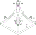
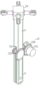
图1为本发明提供的适用于施工场地自动拆装的自动化抱杆装置的结构示意图。Fig. 1 is a structural schematic diagram of an automatic pole holding device suitable for automatic disassembly and assembly at a construction site provided by the present invention.
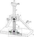
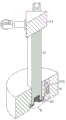
图2为本发明提供的适用于施工场地自动拆装的自动化抱杆装置剖切图。Fig. 2 is a cutaway view of the automatic pole holding device suitable for automatic disassembly and assembly on construction sites provided by the present invention.
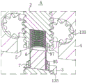
图3为图2所示的A区域的局部放大图。FIG. 3 is a partially enlarged view of area A shown in FIG. 2 .
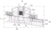
图4为图2所示的B区域的局部放大图。FIG. 4 is a partially enlarged view of area B shown in FIG. 2 .
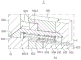
图5为图4所示的C区域的局部放大图。FIG. 5 is a partially enlarged view of area C shown in FIG. 4 .
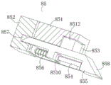
图6为本发明提供的锁定部件的结构示意图。Fig. 6 is a schematic structural diagram of the locking component provided by the present invention.
图7为本发明提供的抱杆顶段和稳定支架之间剖切图。Fig. 7 is a sectional view between the top section of the pole and the stabilizing bracket provided by the present invention.
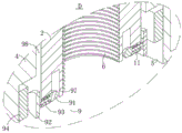
图8为图7所示的D区域的局部放大图。FIG. 8 is a partially enlarged view of area D shown in FIG. 7 .
图9为本发明提供的抱杆顶段和抱杆拼接段拼接后与主动提升机构之间的结构示意图。Fig. 9 is a schematic diagram of the structure between the spliced top section of the pole and the spliced section of the pole provided by the present invention and the active lifting mechanism.
图10为本发明提供的抱杆拼接段的结构示意图。Fig. 10 is a schematic structural view of the pole splicing section provided by the present invention.
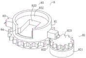
图11为本发明提供的旋紧机构的结构示意图。Fig. 11 is a structural schematic diagram of the tightening mechanism provided by the present invention.
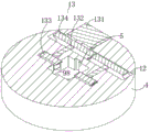
图12为本发明提供的稳定支架上端的剖切图。Fig. 12 is a sectional view of the upper end of the stabilizing bracket provided by the present invention.
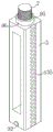
图中: 1、底座;2、抱杆顶段;3、抱杆拼接段;4、稳定支架;5、滑动槽;6、螺纹槽;7、螺纹柱;8、旋紧机构;81、转筒;82、驱动部件;821、驱动电机;822、齿环;823、第一齿轮;83、升降部件;831、液压缸;832、滑动夹座;833、限位槽;84、进入槽口;85、锁定部件;851、连接板;852、卡接板;853、活动槽;854、滑杆;855、滑动件;856、连接弹簧;857、卡接槽;858、第一斜面;859、第二斜面;8510、第一磁性块;8511、第一电磁铁;8512、垫块;9、稳固机构;91、稳固卡件;92、第二磁性块;93、支撑弹簧;94、第二电磁铁;95、对接环体;96、卡孔;97、对接槽;98、让位通槽;10、装置槽;11、伸缩槽;12、安装槽;13、主动提升机构;131、转动电机;132、转轴;133、第二齿轮;134、第三齿轮;135、齿槽;14、牵引滑轮装置;15、引导滑轮;16、定位孔。In the figure: 1. Base; 2. Top section of holding pole; 3. Splicing section of holding pole; 4. Stabilizing support; 5. Sliding groove; 6. Threaded groove; 7. Threaded column; Barrel; 82, driving part; 821, driving motor; 822, gear ring; 823, first gear; 83, lifting part; 831, hydraulic cylinder; ; , the second slope; 8510, the first magnetic block; 8511, the first electromagnet; 8512, the spacer; 9, the stabilizing mechanism; 91, the stabilizing clip; 92, the second magnetic block; Two electromagnets; 95, docking ring body; 96, clamping hole; 97, docking slot; 98, step-through slot; 10, device slot; 11, telescopic slot; 12, installation slot; 13, active lifting mechanism; 131, Rotating motor; 132, rotating shaft; 133, second gear; 134, third gear; 135, tooth groove; 14, traction pulley device; 15, guide pulley; 16, positioning hole.
具体实施方式Detailed ways
以下描述用于揭露本发明以使本领域技术人员能够实现本发明。以下描述中的优选实施例只作为举例,本领域技术人员可以想到其他显而易见的变型。The following description serves to disclose the present invention to enable those skilled in the art to carry out the present invention. The preferred embodiments described below are only examples, and those skilled in the art can devise other obvious variations.
请结合参阅图1至图12涉及的适用于施工场地自动拆装的自动化抱杆装置,包括:底座1、抱杆顶段2和抱杆拼接段3,底座1的顶部固定安装有稳定支架4,稳定支架4的顶部贯通开设有滑动槽5,抱杆顶段2的底端由稳定支架4的顶部滑动延伸至滑动槽5内,抱杆顶段2的底端与抱杆拼接段3的底端均开设有螺纹槽6,抱杆拼接段3的顶端固定安装有用于与螺纹槽6适配的螺纹柱7;Please refer to Fig. 1 to Fig. 12 for the automatic pole holding device suitable for automatic disassembly and assembly on the construction site, including:
稳定支架4的内部安装有主动提升机构13;An
底座1上设置有用于驱动抱杆拼接段3自动与抱杆顶段2旋紧的旋紧机构8,抱杆拼接段3的底端与旋紧机构8活动卡接,旋紧机构8包括转筒81和用于驱动转筒81转动的驱动部件82,转筒81的内部设置有用于对抱杆拼接段3底端进行夹持和抬升的升降部件83。The
为了解决抱杆拼接段3组装难度大,操作繁琐,不够方便的问题,本发明通过设置该自动化抱杆装置解决上述问题;In order to solve the problems of difficult assembly of the pole-holding splicing section 3, cumbersome operation, and insufficient convenience, the present invention solves the above-mentioned problems by setting the automatic pole-holding device;
本发明自动化抱杆装置在使用时,先通过外部牵引机构牵引抱杆顶段2进入滑动槽5内,通过主动提升机构13进行支撑,接着工作人员将一个抱杆拼接段3搬运至旋紧机构8上,使得抱杆拼接段3底端卡接在升降部件83的安装位置上,再通过升降部件83伸长可带动其上的抱杆拼接段3上移,直至该抱杆拼接段3顶端的螺纹柱7与其上方的抱杆拼接段3底端的螺纹槽6对齐,升降部件83停止伸长,接着通过驱动部件82驱动转筒81开始转动,与此同时,升降部件83继续伸长,使得螺纹柱7开始与螺纹槽6螺纹连接,由于升降部件83伸长量是与螺纹柱7旋进的位移量适配设定的,因此,能够保证下方的抱杆拼接段3能够顺利的与上方的抱杆拼接段3螺纹连接,直至两者完全组装在一起,及完成了提升抱杆装置高度的操作,若需要再次提升高度时,重复上述步骤,不同的是抬升部件需要先向下收缩复位,之后才能继续安装下一个抱杆拼接段3;When the automatic pole holding device of the present invention is in use, the top section 2 of the pole holding pole is first pulled into the sliding
通过设置螺纹柱7和螺纹槽6作为连接结构来实现抱杆顶段2和抱杆拼接段3或两个抱杆拼接段3之间的拼接功能,代替了传统使用多个连接结构共同作用的连接方式,在组装过程中只需一次连接动作即可完成,简化了拼接操作,有利于降低拼接难度,并利用旋紧机构8驱动抱杆拼接段3转动和上移,以实现抱杆拼接段3与抱杆顶段2或两个抱杆拼接段3之间自动组装功能,有利于快速调节抱杆装置的高度,进而便于对抱杆装置进行拆装。The splicing function between the pole top section 2 and the pole splicing section 3 or two pole splicing sections 3 is realized by setting the threaded
作为本发明的一种实施例,底座1的顶部开设有装置槽10,转筒81的底端与装置槽10的底壁转动连接,转筒81的顶端由装置槽10内转动贯穿出底座1的顶部。As an embodiment of the present invention, a
作为本发明的一种实施例,驱动部件82包括驱动电机821和齿环822,驱动电机821固定安装在装置槽10的底壁上,齿环822固定套装在转筒81的底端,驱动电机821的输出端固定安装有与齿环822啮合的第一齿轮823。As an embodiment of the present invention, the driving
为了能够带动抱杆拼接段3能够与抱杆顶段2转动螺纹拼接,通过设置驱动部件82驱动转筒81和抱杆拼接段3转动,在驱动部件82带动转筒81转动时,通过驱动电机821转动,可使得第一齿轮823和齿环822一起转动,而转筒81则跟随齿环822同步转动,并带动升降部件83和升降部件83上的抱杆拼接段3一起转动,最终可使得螺纹柱7能够旋紧螺纹槽6内。In order to be able to drive the pole-holding splicing section 3 to be rotated and threadedly spliced with the pole-holding top section 2, the rotating
作为本发明的一种实施例,升降部件83包括固定安装在转筒81底壁的液压缸831,液压缸831的伸缩端固定安装有与转筒81内壁滑动连接的滑动夹座832,滑动夹座832的顶部开设有用于放置抱杆拼接段3底端的限位槽833,转筒81的外侧开设有与限位槽833连通的进入槽口84。As an embodiment of the present invention, the lifting
在通过使用驱动部件82驱动转筒81和抱杆拼接段3转动时,由于抱杆拼接段3与抱杆顶段2螺纹连接后,抱杆拼接段3高度会发生变化,因此为了确保抱杆拼接段3与抱杆顶段2顺利组装,通过设置升降部件83同步调节抱杆拼接段3的高度,抬升部件在使用时,工作人员由进入槽口84将抱杆拼接段3安装在滑动夹座832中,安装完成后再通过液压缸831伸长,可带动滑动夹座832同步在转筒81内侧上移,同时可带动其上的抱杆拼接段3上移,以适应抱杆拼接段3组装时的高度变化,有利于保证抱杆拼接段3组装后底端得到支撑,进而辅助完成自动拆装操作。When the
作为本发明的一种实施例,旋紧机构8还包括用于对转筒81位置进行锁定的锁定部件85,锁定部件85包括两个连接板851和两个卡接板852,两个连接板851对称固定安装在转筒81的外侧,卡接板852固定安装在底座1顶部与连接板851相对应的位置上,连接板851的内部开设有活动槽853,活动槽853靠近转筒81的一侧与转筒81内壁之间连通;As an embodiment of the present invention, the screwing
具体的,所述活动槽853下端的两个内侧壁之间固定安装有滑杆854,滑杆854外侧滑动套装有滑动件855,滑动件855外侧与活动槽853内侧壁滑动连接,滑杆854的外侧套装有两端固定安装在活动槽853与滑动件855之间的连接弹簧856,卡接板852靠近连接板851的一侧开设有卡接槽857,滑动件855的远离转筒81的一端滑动贯穿连接板851后与卡接槽857滑动插接,滑动件855靠近转筒81的一端由活动槽853内滑动贯穿至转筒81内侧,滑动件855延伸至转筒81内侧的一端设有第一斜面858,滑动夹座832的下端设有与第一斜面858滑动贴合的第二斜面859;Specifically, a sliding
滑动件855的下端固定安装有第一磁性块8510,活动槽853内壁的一侧固定安装有与第一磁性块8510相对设置的第一电磁铁8511,滑动件855的顶部固定安装有用于为抬升后的滑动夹座832底部提供支撑的垫块8512。The lower end of the
由于转筒81是与装置槽10之间转动连接的,且转筒81又需要承担抱杆顶段2和抱杆拼接段3的大部分重量,因此在转筒81处于非转动情况下,转筒81的稳定性难以得到保证,因此通过设置锁定部件85来解决上述问题;Since the
本发明中,所述锁定部件85在使用时若需要增加抱杆装置的高度,则工作人员首先将抱杆拼接段3安装在滑动夹座832上后,在液压缸831驱动滑动夹座832上移过程中,滑动夹座832底端的第二斜面859对第一斜面858的挤压力重心逐渐上移,并在连接弹簧856的弹力作用下,可带动滑动件855和垫块8512跟随滑动夹座832同步水平滑动,使得滑动件855端部逐渐与卡接槽857分离,在滑动夹座832带动抱杆拼接段3到达对接位置后,液压缸831停止伸长,由于第一斜面858与第二斜面859仍处于贴合状态,对滑动件855产生阻碍作用,因此滑动件855不再继续滑动,此时,滑动件855的端部也完全与卡接槽857分离开,而转筒81就不再受到卡接作用,进而解除对转筒81的锁定作用,而转筒81就可以在驱动部件82的驱动作用下带动抱杆拼接段3转动,在转筒81转动的过程中,抱杆拼接段3会上升,通过控制液压缸831继续带动滑动夹座832上移对抱杆拼接段3的底端进行调节支撑,而在连接弹簧856的弹力作用下,滑动件855和垫块8512继续滑动,当抱杆拼接段3完成拼接后,此时滑动夹座832停止伸长,而垫块8512也正好移动至滑动夹座832的底端,并与滑动夹座832底部贴合,为滑动夹座832提供支撑,以减轻液压缸831的负担;In the present invention, if the locking
而在高压铁塔搭建完成后,需要拆卸抱杆拼接段3时,先通过旋紧机构8将抱杆拼接段3旋转拆除,此时转筒81不再转动,并正好使得连接板851与卡接板852对齐,在升降部件83带动抱杆拼接段3下移之前,第一电磁铁8511开始通电,并产生与第一磁性块8510相同的磁性,进而可推动第一磁性块8510、滑动件855和垫块8512一起向远离滑动夹座832方向滑动,直至滑动件855上的第一斜面858与滑动夹座832上的第二斜面859贴合,此时通过液压缸831驱动滑动夹座832开始下移,在第一斜面858与第二斜面859滑动挤压作用下,可进一步挤压滑动件855滑动,直至滑动夹座832下降至最低位置,正好使得滑动件855的另一端卡接在卡接槽857内,完成对转筒81的锁定操作;After the high-voltage iron tower is built, when it is necessary to disassemble the pole-holding splicing section 3, the pole-holding splicing section 3 is first rotated and removed by the
通过设置锁定部件85,一方面,可用于对转筒81的位置进行锁定,在转筒81处于非转动状态时,通过滑动件855与连接板851卡接,使得转筒81无法正常转动,进而起到锁定作用,有利于避免抱杆装置在吊起建材过程中转筒81在发生相对转动,可提升抱杆顶段2和抱杆拼接段3使用时的稳定性;另一方面,在滑动夹座832到达最高位置时,通过滑动件855和垫块8512继续滑动,使得垫块8512滑动至滑动夹座832的底部位置为其提供支撑,有利于避免液压缸831独自承担大部分重力,从而对液压缸831起到一定的保护作用,并且有利于提升滑动夹座832的稳定性,更好的为抱杆顶段2和抱杆拼接段3提供支撑。By setting the locking
作为本发明的一种实施例,滑动槽5下端内表面对称连通有两个伸缩槽11,抱杆顶段2的下端与抱杆拼接段3的下端均设置有稳固机构9,稳固机构9包括滑动安装在伸缩槽11内的稳固卡件91和两个让位通槽98,稳固卡件91远离滑动槽5的一端由伸缩槽11内贯穿出去后固定安装有第二磁性块92,两个让位通槽98对称开设在滑动槽5的内侧壁上,稳固卡件91的外侧套装有两端固定在伸缩槽11与稳固卡件91之间的支撑弹簧93,滑动槽5侧壁上对称固定安装有两个与第二磁性块92相对应的第二电磁铁94;As an embodiment of the present invention, the inner surface of the lower end of the sliding
抱杆拼接段3的顶端固定安装有套设在螺纹柱7外侧的对接环体95,对接环体95的外侧对称开设有两个与稳固卡件91相适配的卡孔96,稳固卡件91远离第二磁性块92的一端滑动延伸出伸缩槽11后与卡孔96卡接,抱杆拼接段3的底端与抱杆顶段2的底端均开设有用于与对接环体95对接的对接槽97,对接环体95的顶端外侧设置成圆锥面,稳固卡件91的端部设置成圆弧形。The top of the pole splicing section 3 is fixedly installed with a
由于抱杆顶段2与抱杆拼接段3为螺纹连接方式,在使用过程中可能出现松动,因此为了进一步提升两者连接时的稳定性,通过设置稳固机构9来解决上述问题;Since the pole top section 2 and the pole splicing section 3 are threadedly connected, loosening may occur during use. Therefore, in order to further improve the stability of the connection between the two, a stabilizing
在抱杆拼接段3与抱杆顶段2拼接过程中,螺纹柱7先进入螺纹槽6内,之后对接环体95进入到对接槽97内,在对接环体95顶端与稳固卡件91接触时,由于对接环体95顶端为圆锥形,且稳固卡件91端部为圆弧形,在两者接触后,随着对接环体95上移,可挤压稳固卡件91向伸缩槽11内收缩,同时挤压支撑弹簧93收缩,使得对接环体95的顶端能够顺利旋转通过稳固卡件91,当卡孔96转动至与稳固卡件91对齐时,而螺纹柱7也正好到达最大旋紧位置,此时,在支撑弹簧93的弹力作用下,可使得稳固卡件91卡接在卡孔96内,进而对接环体95进行锁定;During the splicing process of the pole-holding splicing section 3 and the pole-holding top section 2, the threaded
而在需要拆卸抱杆拼接段3时,此时由于第二磁性块92是与第二电磁铁94对齐的,在第二电磁铁94通电后可产生与第二磁性块92相反的磁力,进而可吸引第二磁性块92和稳固卡件91一起活动,直至第二磁性块92与第二电磁铁94贴合,正好使得稳固卡件91与卡孔96完全分离,进而解除了对对接环体95的锁定作用,之后便可以通过驱动转筒81转动来对抱杆拼接段3进行拆卸了;And when needing to disassemble the pole-holding splicing section 3, now because the second
通过设置对接环体95、第二电磁铁94、稳固机构9配合使用,可用于进一步增加抱杆拼接段3与抱杆顶段2之间的连接牢固度,在抱杆拼接段3与抱杆顶段2到达组装位置后,可使得稳固卡件91正好与卡孔96卡接,进而对对接环体95和抱杆拼接段3起到锁定作用,有利于避免抱杆拼接段3与抱杆顶段2出现松动,提升了两者连接的稳固性,同时利用第二电磁铁94的磁力作用,可将稳固机构9调整至解锁状态,实现了对抱杆拼接段3与抱杆顶段2之间的自动锁定和自动解锁功能,在拼装过程中实现自动化拼装功能,进而有利于减轻工作人员的工作负担,并加快拆装的速度。By arranging the
作为本发明的一种实施例,稳定支架4的内部开设有安装槽12,主动提升机构13设置在安装槽12内,主动提升机构13包括转动电机131和两个对称转动安装在抱杆顶段2两侧的转轴132,转轴132的两端分别固定安装有第二齿轮133和第三齿轮134,且两个第三齿轮134相啮合,转动电机131固定安装在安装槽12内部,转动电机131的输出端与其中一个第三齿轮134的一侧固定连接,抱杆顶段2和抱杆拼接段3与第二齿轮133相对应的两侧均开设有多个均匀线性排布的齿槽135,第二齿轮133与抱杆顶段2侧面的齿槽135相啮合。As an embodiment of the present invention, a mounting
在调节抱杆装置的高度时,若抱杆拼接段3拼接数量较多,所需要的外部牵引力就会增加,因此为了减小外部牵引机构驱动抱杆装置上移的压力,通过设置主动提升机构13实现上述功能,主动提升机构13在使用时,即需要增加抱杆拼接段3的过程,通过外部牵引机构拉动抱杆顶段2和抱杆拼接段3一起上移,同时,通过转动电机131转动,可使得两个第三齿轮134一起转动,并使得两个转轴132和两个第二齿轮133一同转动,由于第二齿轮133与齿槽135啮合,在第二齿轮133的转动作用下,可对齿槽135产生向上的推力,进而辅助抱杆拼接段3上移,在到达提升高度后,外部的牵引机构和转动电机131都停止运行,而抱杆拼接段3则保持静止;When adjusting the height of the pole-holding device, if the number of pole-holding splicing sections 3 is large, the required external traction will increase. Therefore, in order to reduce the pressure of the external traction mechanism to drive the pole-holding device to move upward, an active lifting mechanism is provided 13 realizes the above functions. When the
通过设置该主动提升机构13,一方面,可辅助抱杆拼接段3上移和下移,有利于减轻外部牵引机构的驱动负担,在双动力驱动条件下,使得抱杆拼接段3升降动作更加轻松、流畅;另一方面,通过第二齿轮133与齿槽135之间的啮合作用,可增强抱杆拼接段3与稳定支架4之间的联系,使得两者之间滑动关系更为牢靠,有利于提升稳固支架与抱杆拼接段3之间的连接稳定性,在升降过程中更加安全性更高,有利于避免出现较大程度的晃动。By setting the
作为本发明的一种实施例,抱杆顶段2的顶端固定安装有牵引滑轮装置14,稳定支架4的支腿上固定安装有引导滑轮15。As an embodiment of the present invention, a
牵引滑轮装置14与引导滑轮15通过之间通过绳索传动连接,用于与外部的牵引机构连接,完成对建材的吊起作业。The
作为本发明的一种实施例,抱杆顶段2与抱杆拼接段3均为四棱柱,抱杆顶段2与抱杆拼接段3拼接后的四个棱柱面对应重合。As an embodiment of the present invention, both the pole top section 2 and the pole splicing section 3 are quadrangular prisms, and the four prism surfaces after the splicing of the pole top section 2 and the pole splicing section 3 overlap correspondingly.
作为本发明的一种实施例,底座1的顶部均匀圆周分布有多个定位孔16,在对底座1进行固定时,使用定位销穿过定位孔16与地面进行固定。As an embodiment of the present invention, a plurality of positioning holes 16 are evenly distributed around the top of the
本发明的提供的适用于施工场地自动拆装的自动化抱杆装置的工作原理:The working principle of the automatic pole holding device suitable for automatic disassembly and assembly of the construction site provided by the present invention:
步骤一:在需要继续组装抱杆拼接段3来提升抱杆装置的高度时,先通过外部牵引机构牵引抱杆顶段2进入滑动槽5内,通过主动提升机构13进行支撑,然后通过主动提升机构13提升抱杆拼接段3沿着稳定支架4上移,在抱杆拼接段3顶端上升至滑动槽5下端的指定位置后,主动提升机构13停止运行,并使得抱杆顶段2停止上升;Step 1: When it is necessary to continue to assemble the pole-holding splicing section 3 to raise the height of the pole-holding device, first pull the pole-holding top section 2 into the sliding
步骤二:将另外一个抱杆拼接段3搬运至升降部件83上,再通过升降部件83伸长可带动其上的抱杆拼接段3上移,直至到达设定位置,升降部件83停止伸长,此时锁定部件85解除对转筒81的锁定作用;Step 2: Move another pole-holding splicing section 3 to the lifting
步骤三:接着通过驱动部件82驱动转筒81开始转动,与此同时,升降部件83继续伸长,使得螺纹柱7开始与螺纹槽6螺纹连接,直至两者完全组装在一起,正好使得稳固机构9对处于锁定状态,完成两个拼接段之间的组装;Step 3: Then drive the
步骤四:在拆卸拼接段时,先通过旋紧机构8带动拼接段旋转解除连接关系,再通过旋紧机构8带动解除连接关系的抱杆拼接段3下移,然后将抱杆拼接段3拆下下来即可,接着,再通过主动提升机构驱动下一个抱杆拼接段3下降至与旋紧机构8接触位置,便开始对该抱杆拼接段3进行拆卸,如此重复操作。Step 4: When disassembling the splicing section, first use the
以上显示和描述了本发明的基本原理、主要特征和本发明的优点。本行业的技术人员应该了解,本发明不受上述实施例的限制,上述实施例和说明书中描述的只是本发明的原理,在不脱离本发明精神和范围的前提下本发明还会有各种变化和改进,这些变化和改进都落入要求保护的本发明的范围内,本发明要求的保护范围由所附的权利要求书及其等同物界定。The basic principles, main features and advantages of the present invention have been shown and described above. Those skilled in the art should understand that the present invention is not limited by the above-mentioned embodiments. What are described in the above-mentioned embodiments and the description are only the principles of the present invention. Changes and improvements, these changes and improvements all fall within the scope of the claimed invention, and the protection scope of the present invention is defined by the appended claims and their equivalents.
Claims (10)
Priority Applications (1)
| Application Number | Priority Date | Filing Date | Title |
|---|---|---|---|
| CN202310439727.9A CN116335466B (en) | 2023-04-23 | 2023-04-23 | Automatic pole holding device suitable for automatic disassembly and assembly of construction site and splicing method |
Applications Claiming Priority (1)
| Application Number | Priority Date | Filing Date | Title |
|---|---|---|---|
| CN202310439727.9A CN116335466B (en) | 2023-04-23 | 2023-04-23 | Automatic pole holding device suitable for automatic disassembly and assembly of construction site and splicing method |
Publications (2)
| Publication Number | Publication Date |
|---|---|
| CN116335466A true CN116335466A (en) | 2023-06-27 |
| CN116335466B CN116335466B (en) | 2026-05-26 |
Family
ID=86885964
Family Applications (1)
| Application Number | Title | Priority Date | Filing Date |
|---|---|---|---|
| CN202310439727.9A Active CN116335466B (en) | 2023-04-23 | 2023-04-23 | Automatic pole holding device suitable for automatic disassembly and assembly of construction site and splicing method |
Country Status (1)
| Country | Link |
|---|---|
| CN (1) | CN116335466B (en) |
Cited By (1)
| Publication number | Priority date | Publication date | Assignee | Title |
|---|---|---|---|---|
| CN112360225A (en) * | 2020-11-25 | 2021-02-12 | 国网山东省电力公司烟台供电公司 | Telescopic holding pole for assembling iron tower |
Citations (7)
| Publication number | Priority date | Publication date | Assignee | Title |
|---|---|---|---|---|
| JP2002147063A (en) * | 2000-11-10 | 2002-05-22 | Kaihatsu Denki Kk | Iron tower intermediate raising device and iron tower intermediate raising method |
| EP3473785A1 (en) * | 2017-10-20 | 2019-04-24 | EL-Björn AB | Telescopic mast |
| CN210013553U (en) * | 2019-04-26 | 2020-02-04 | 宝鸡华源电力设备有限公司 | Holding pole suitable for assembling transmission line iron tower |
| CN210296603U (en) * | 2019-08-28 | 2020-04-10 | 安徽徽天标准件制造有限公司 | Be convenient for install adjustable communication equipment and embrace pole |
| CN112360225A (en) * | 2020-11-25 | 2021-02-12 | 国网山东省电力公司烟台供电公司 | Telescopic holding pole for assembling iron tower |
| CN212953804U (en) * | 2020-08-31 | 2021-04-13 | 四川省秭源建设工程有限公司 | Holding pole for assembling power transmission line iron tower |
| CN217176039U (en) * | 2022-01-17 | 2022-08-12 | 山东广域科技有限责任公司 | Electric pole with liftable cross arm |
-
2023
- 2023-04-23 CN CN202310439727.9A patent/CN116335466B/en active Active
Patent Citations (7)
| Publication number | Priority date | Publication date | Assignee | Title |
|---|---|---|---|---|
| JP2002147063A (en) * | 2000-11-10 | 2002-05-22 | Kaihatsu Denki Kk | Iron tower intermediate raising device and iron tower intermediate raising method |
| EP3473785A1 (en) * | 2017-10-20 | 2019-04-24 | EL-Björn AB | Telescopic mast |
| CN210013553U (en) * | 2019-04-26 | 2020-02-04 | 宝鸡华源电力设备有限公司 | Holding pole suitable for assembling transmission line iron tower |
| CN210296603U (en) * | 2019-08-28 | 2020-04-10 | 安徽徽天标准件制造有限公司 | Be convenient for install adjustable communication equipment and embrace pole |
| CN212953804U (en) * | 2020-08-31 | 2021-04-13 | 四川省秭源建设工程有限公司 | Holding pole for assembling power transmission line iron tower |
| CN112360225A (en) * | 2020-11-25 | 2021-02-12 | 国网山东省电力公司烟台供电公司 | Telescopic holding pole for assembling iron tower |
| CN217176039U (en) * | 2022-01-17 | 2022-08-12 | 山东广域科技有限责任公司 | Electric pole with liftable cross arm |
Cited By (1)
| Publication number | Priority date | Publication date | Assignee | Title |
|---|---|---|---|---|
| CN112360225A (en) * | 2020-11-25 | 2021-02-12 | 国网山东省电力公司烟台供电公司 | Telescopic holding pole for assembling iron tower |
Also Published As
| Publication number | Publication date |
|---|---|
| CN116335466B (en) | 2026-05-26 |
Similar Documents
| Publication | Publication Date | Title |
|---|---|---|
| CN113338695B (en) | Bearing platform type cable terminal tower | |
| CN116040461B (en) | Hoisting clamp for H-shaped steel beam | |
| CN219672108U (en) | Combined type elevator shaft climbing barrel mold device | |
| CN110593123B (en) | Bent cap swivel construction equipment and construction method thereof | |
| CN211813197U (en) | a three-dimensional warehouse | |
| CN117471631A (en) | An electronic information network transmission optical cable traction equipment | |
| CN115418974B (en) | An adjustable hanging basket for bridge construction | |
| CN116588808B (en) | Prefabricated stair hoisting equipment | |
| CN222184105U (en) | Frame post template reinforcing apparatus is built in room | |
| CN118223676B (en) | Frame post template reinforcing apparatus is built in room | |
| CN118289625B (en) | Hoisting clamping device for bridge construction | |
| CN112360225A (en) | Telescopic holding pole for assembling iron tower | |
| CN112627589A (en) | Environment-friendly energy-saving building construction support frame | |
| CN214660264U (en) | An improved new type of anchor pile for construction | |
| CN114215483B (en) | Hanging anchor frame and low-clearance rotary drilling rig comprising same | |
| CN222348611U (en) | Easy-to-assemble lifting equipment for installing ventilation and smoke exhaust equipment | |
| CN224182942U (en) | A mechanical coupler assembly machine | |
| CN119177655B (en) | Pile machine directional traction device for building construction and use method thereof | |
| CN119843663B (en) | Anti-offset positioning device and positioning method for pile driver for ultra-thick hard rock | |
| CN222277670U (en) | A pipeline placement device for municipal engineering | |
| CN111977518A (en) | External wall panel hoisting device for assembly type building construction | |
| CN219929415U (en) | Hoisting winch for building construction | |
| CN115419065B (en) | A geotechnical engineering pile extraction auxiliary device and auxiliary method | |
| CN116537600B (en) | A support device and method for large-span steel structures | |
| CN222732777U (en) | High-pole lamp |
Legal Events
| Date | Code | Title | Description |
|---|---|---|---|
| PB01 | Publication | ||
| PB01 | Publication | ||
| SE01 | Entry into force of request for substantive examination | ||
| SE01 | Entry into force of request for substantive examination | ||
| GR01 | Patent grant | ||
| GR01 | Patent grant |