CN116328965A - Belt cleaning mechanism with motor of spiral screen centrifuge - Google Patents
Belt cleaning mechanism with motor of spiral screen centrifuge Download PDFInfo
- Publication number
- CN116328965A CN116328965A CN202310072579.1A CN202310072579A CN116328965A CN 116328965 A CN116328965 A CN 116328965A CN 202310072579 A CN202310072579 A CN 202310072579A CN 116328965 A CN116328965 A CN 116328965A
- Authority
- CN
- China
- Prior art keywords
- cleaning pipe
- material bin
- pipe
- plate
- material cleaning
- Prior art date
- Legal status (The legal status is an assumption and is not a legal conclusion. Google has not performed a legal analysis and makes no representation as to the accuracy of the status listed.)
- Granted
Links
- 238000004140 cleaning Methods 0.000 title claims abstract description 137
- 239000000463 material Substances 0.000 claims abstract description 204
- XLYOFNOQVPJJNP-UHFFFAOYSA-N water Substances O XLYOFNOQVPJJNP-UHFFFAOYSA-N 0.000 claims abstract description 110
- 239000007921 spray Substances 0.000 claims description 44
- 230000003014 reinforcing effect Effects 0.000 claims description 13
- 238000009434 installation Methods 0.000 claims description 3
- 238000005507 spraying Methods 0.000 abstract description 7
- 238000011010 flushing procedure Methods 0.000 abstract description 5
- 238000010586 diagram Methods 0.000 description 7
- 238000005406 washing Methods 0.000 description 4
- 238000000034 method Methods 0.000 description 3
- 238000012986 modification Methods 0.000 description 3
- 230000004048 modification Effects 0.000 description 3
- 230000001681 protective effect Effects 0.000 description 3
- 238000005516 engineering process Methods 0.000 description 2
- 230000009286 beneficial effect Effects 0.000 description 1
- 230000007812 deficiency Effects 0.000 description 1
- 238000001035 drying Methods 0.000 description 1
- 239000002245 particle Substances 0.000 description 1
- 230000002787 reinforcement Effects 0.000 description 1
- 238000007789 sealing Methods 0.000 description 1
- 239000007787 solid Substances 0.000 description 1
Images


Classifications
-
- B—PERFORMING OPERATIONS; TRANSPORTING
- B04—CENTRIFUGAL APPARATUS OR MACHINES FOR CARRYING-OUT PHYSICAL OR CHEMICAL PROCESSES
- B04B—CENTRIFUGES
- B04B15/00—Other accessories for centrifuges
- B04B15/06—Other accessories for centrifuges for cleaning bowls, filters, sieves, inserts, or the like
-
- Y—GENERAL TAGGING OF NEW TECHNOLOGICAL DEVELOPMENTS; GENERAL TAGGING OF CROSS-SECTIONAL TECHNOLOGIES SPANNING OVER SEVERAL SECTIONS OF THE IPC; TECHNICAL SUBJECTS COVERED BY FORMER USPC CROSS-REFERENCE ART COLLECTIONS [XRACs] AND DIGESTS
- Y02—TECHNOLOGIES OR APPLICATIONS FOR MITIGATION OR ADAPTATION AGAINST CLIMATE CHANGE
- Y02W—CLIMATE CHANGE MITIGATION TECHNOLOGIES RELATED TO WASTEWATER TREATMENT OR WASTE MANAGEMENT
- Y02W30/00—Technologies for solid waste management
- Y02W30/50—Reuse, recycling or recovery technologies
- Y02W30/62—Plastics recycling; Rubber recycling
Landscapes
- Cleaning By Liquid Or Steam (AREA)
- Combined Means For Separation Of Solids (AREA)
Abstract
Description
技术领域technical field
本发明涉及电动控制技术领域,具体为一种螺旋筛网离心机的带电动机的清洗机构。The invention relates to the technical field of electric control, in particular to a cleaning mechanism with a motor of a spiral screen centrifuge.
背景技术Background technique
螺旋筛网(螺旋过滤)离心机是一种连续工作的过滤离心机,可以连续完成进料、分离、洗涤、干燥和卸料的全部工序,具备产量大、效率高的特点。在工作中,筛网中的固体颗粒通过筛网的倾斜角度和螺旋刮刀与筛网的速差从小直径向大直径传送。Spiral screen (spiral filter) centrifuge is a continuous working filter centrifuge, which can continuously complete the entire process of feeding, separating, washing, drying and unloading, and has the characteristics of large output and high efficiency. During operation, the solid particles in the screen are conveyed from the small diameter to the large diameter through the inclination angle of the screen and the speed difference between the spiral scraper and the screen.
公告号为CN209271688U的中国专利公开了一种能够稳定运行过程的差速螺旋筛网离心机,包括:底座、主电动机、主带轮、差速器、输出空心轴、输出轴、筛笼组件、刮刀组件、物料仓、保护外壳和进料管,底座上设置有主电动机,主电动机一端连接有主带轮,主带轮内侧设置有差速器,差速器一侧设置有输出空心轴,输出空心轴一端设置有输出轴和筛笼组件,输出轴一端设置有刮刀组件,输出空心轴上设置有保护外壳,保护外壳一端设置有物料仓,物料仓一端设置有进料管,所述的物料仓上设置有清洗机构,所述清洗机构包括吸水管和物料清洗管,所述吸水管设置于筛笼组件外侧,所述吸水管穿过物料仓,所述吸水管固定于物料仓上,所述吸水管与物料仓之间采用焊接,所述物料清洗管设置于进料管一侧,所述物料清洗管固定于物料仓上,所述物料清洗管与物料仓之间采用螺栓连接。The Chinese patent with the notification number CN209271688U discloses a differential spiral screen centrifuge capable of stable operation, including: base, main motor, main pulley, differential, output hollow shaft, output shaft, screen cage assembly, The scraper assembly, the material bin, the protective shell and the feeding pipe, the main motor is arranged on the base, the main pulley is connected to one end of the main motor, the differential is arranged inside the main pulley, and the output hollow shaft is arranged on the side of the differential. One end of the output hollow shaft is provided with an output shaft and a screen cage assembly, one end of the output shaft is provided with a scraper assembly, the output hollow shaft is provided with a protective shell, one end of the protective shell is provided with a material bin, and one end of the material bin is provided with a feed pipe. The material bin is provided with a cleaning mechanism, the cleaning mechanism includes a water suction pipe and a material cleaning pipe, the water suction pipe is arranged outside the screen cage assembly, the water suction pipe passes through the material bin, and the water suction pipe is fixed on the material bin, The water suction pipe and the material bin are welded, the material cleaning pipe is arranged on one side of the feed pipe, the material cleaning pipe is fixed on the material bin, and the material cleaning pipe and the material bin are connected by bolts.
上述现有技术中公开了清洗机构,清洗机构包括吸水管和物料清洗管,吸水管和物料清洗管的出水面积是固定的,在清洗筛笼组件时,喷到清洗筛笼组件上的面积是只有吸水管和物料清洗管的面积,每次喷到筛笼组件上的冲洗面积小,冲洗效率低,进而不便于筛笼组件的清洗。The cleaning mechanism is disclosed in the above-mentioned prior art. The cleaning mechanism includes a water suction pipe and a material cleaning pipe. The water outlet area of the water suction pipe and the material cleaning pipe is fixed. When cleaning the screen cage assembly, the area sprayed on the cleaning screen cage assembly is Only the area of the water suction pipe and the material cleaning pipe, the washing area sprayed on the screen cage assembly each time is small, the flushing efficiency is low, and it is inconvenient to clean the screen cage assembly.
发明内容Contents of the invention
针对上述存在的技术不足,本发明的目的是提供一种螺旋筛网离心机的带电动机的清洗机构,具有提高清洗机构的冲洗面积,提高冲洗效率的优点。In view of the above-mentioned technical deficiencies, the object of the present invention is to provide a cleaning mechanism with a motor of a spiral screen centrifuge, which has the advantages of increasing the washing area of the cleaning mechanism and improving the washing efficiency.
为解决上述技术问题,本发明采用如下技术方案:In order to solve the problems of the technologies described above, the present invention adopts the following technical solutions:
本发明提供一种螺旋筛网离心机的带电动机的清洗机构,包括设置在物料仓上的吸水管以及设置在物料仓上的且位于筛笼组件内的第一物料清洗管,所述吸水管位于筛笼组件上方,所述吸水管的一端位于物料仓内且设有与吸水管连通的中空的第一喷水板,所述第一喷水板为弧形板,所述吸水管的另一端位于物料仓的上方,所述第一物料清洗管的一端进入筛笼组件内且在进入的一端设有中空的第二喷水板,所述第二喷水板为弧形板,所述第一物料清洗管的另一端位于物料仓的外壁,所述第一物料清洗管和吸水管在延伸出物料仓的一端均通过软管连通有蓄水槽,所述软管上设有抽水泵,所述第一喷水板和第二喷水板在朝向筛笼组件的一侧均开设有若干出水孔。The invention provides a cleaning mechanism with a motor of a spiral screen centrifuge, which includes a water suction pipe arranged on the material bin and a first material cleaning pipe arranged on the material bin and located in the screen cage assembly. The water suction pipe Located above the screen cage assembly, one end of the water suction pipe is located in the material bin and is provided with a hollow first water spray plate communicated with the water suction pipe, the first water spray plate is an arc plate, and the other end of the water suction pipe One end is located above the material bin, one end of the first material cleaning pipe enters into the screen cage assembly and a hollow second water spray plate is provided at the entered end, the second water spray plate is an arc plate, the The other end of the first material cleaning pipe is located on the outer wall of the material bin, the end of the first material cleaning pipe and the water suction pipe extending out of the material bin are connected to a water storage tank through a hose, and a water pump is provided on the hose, The first water spray plate and the second water spray plate are provided with several water outlet holes on the side facing the screen cage assembly.
通过采用上述技术方案,第一喷水板和第二喷水板的设置增大了吸水管和第一物料清洗管的喷射面积,提高了喷射到筛笼组件上的冲洗面积,提高冲洗效率,抽水泵通过软管将蓄水槽内的水吸到第一喷水板和第二喷水板上,吸水管位于筛笼组件上方,第一物料清洗管的一端进入筛笼组件内,此时便于第一喷水板和第二喷水板清洗筛笼组件。By adopting the above technical scheme, the setting of the first water spray plate and the second water spray plate increases the spray area of the water suction pipe and the first material cleaning pipe, improves the wash area sprayed on the screen cage assembly, and improves the wash efficiency. The water pump sucks the water in the storage tank to the first water spray plate and the second water spray plate through the hose, the water suction pipe is located above the screen cage assembly, and one end of the first material cleaning pipe enters the screen cage assembly, at this time It is convenient for the first water spray plate and the second water spray plate to clean the screen cage assembly.
优选地,所述第一物料清洗管穿设在物料仓上,所述物料仓上开设有供第一物料清洗管穿出的移动孔,所述移动孔的孔壁上设有导向块,所述第一物料清洗管外壁沿第一物料清洗管长度方向开设有供导向块滑移的滑槽,所述物料仓上设有推动第一物料清洗管在移动孔内往返移动的驱动件。Preferably, the first material cleaning pipe is installed on the material bin, and a moving hole for the first material cleaning pipe to pass through is opened on the material bin, and a guide block is provided on the hole wall of the moving hole, so that The outer wall of the first material cleaning pipe is provided with a chute along the length direction of the first material cleaning pipe for the sliding of the guide block, and the material bin is provided with a driving member to push the first material cleaning pipe to move back and forth in the moving hole.
优选地,所述驱动件包括转动连接在物料仓外壁的第一齿轮,所述第一齿轮与第一物料清洗管同轴设置,且所述第一齿轮中部开设有供第一物料清洗管穿出的穿出孔,所述第一物料清洗管与穿出孔螺纹连接,所述物料仓外壁设有驱动第一齿轮转动的第一带动件。Preferably, the driving member includes a first gear rotatably connected to the outer wall of the material bin, the first gear is arranged coaxially with the first material cleaning pipe, and the middle part of the first gear is opened for the first material cleaning pipe to pass through. The first material cleaning pipe is threadedly connected to the outlet hole, and the outer wall of the material bin is provided with a first driving member that drives the first gear to rotate.
优选地,所述第一带动件包括设置在物料仓上的L形驱动板,所述驱动板的水平边与物料仓外壁连接,竖直边与物料仓相对,所述驱动板的竖直边与第一齿轮错位分布,所述驱动板的竖直边转动连接有第一摆杆,所述第一齿轮上设有第二摆杆,所述第二摆杆的一端设有与穿出孔同轴的驱动筒,所述驱动筒沿穿出孔边缘分布且固定在第一齿轮上,所述第二摆杆远离驱动筒的一端铰接有连杆,所述连杆远离第二摆杆的一端铰接在第一摆杆上,所述驱动板上设有驱动第一摆杆转动的电动机。Preferably, the first driving member includes an L-shaped driving plate arranged on the material bin, the horizontal side of the driving plate is connected to the outer wall of the material bin, the vertical side is opposite to the material bin, and the vertical side of the driving plate is Displaced distribution with the first gear, the vertical side of the driving plate is connected with the first swing rod in rotation, the first gear is provided with the second swing rod, and one end of the second swing rod is provided with a through hole A coaxial drive cylinder, the drive cylinder is distributed along the edge of the exit hole and fixed on the first gear, the end of the second swing rod away from the drive cylinder is hinged with a connecting rod, and the connecting rod is away from the end of the second swing rod One end is hinged on the first fork, and the drive plate is provided with a motor to drive the first fork to rotate.
优选地,所述物料仓上在第一物料清洗管的旁边平行设有第二物料清洗管,所述物料仓上设有供第二物料清洗管穿出的移出孔,所述第二物料清洗管在移出孔内往复移动,所述物料仓上设有驱动第二物料清洗管移动的第二带动件。Preferably, a second material cleaning pipe is provided parallel to the first material cleaning pipe on the material bin, and a removal hole for the second material cleaning pipe to pass through is provided on the material bin, and the second material cleaning pipe The pipe reciprocates in the removal hole, and the material bin is provided with a second driving member that drives the movement of the second material cleaning pipe.
优选地,所述第二带动件包括转动设置在物料仓上的第二齿轮,所述第二齿轮与第一齿轮啮合,所述移出孔的孔壁上设有限位块,所述第二物料清洗管上开设有供限位块往复移动的驱动槽,所述第二齿轮上开设有供第二物料清洗管同轴穿出的连接孔,所述第二物料清洗管与连接孔的孔壁螺纹连接。Preferably, the second driving member includes a second gear rotatably arranged on the material bin, the second gear meshes with the first gear, a limit block is provided on the hole wall of the removal hole, and the second material The cleaning pipe is provided with a drive slot for the reciprocating movement of the limit block, and the second gear is provided with a connection hole for the second material cleaning pipe to pass through coaxially, and the hole wall of the second material cleaning pipe and the connection hole threaded connection.
优选地,所述驱动筒外壁螺纹连接有限位杆,所述限位杆穿过驱动筒与第一物料清洗管外壁抵触,所述限位杆的数量为若干,且沿驱动筒的周边均匀分布。Preferably, the outer wall of the drive cylinder is threaded to limit rods, and the limit rods pass through the drive cylinder to interfere with the outer wall of the first material cleaning pipe. The number of the limit rods is several, and they are evenly distributed along the periphery of the drive cylinder .
优选地,所述物料仓上端壁开设有安装孔,所述物料仓上设有封闭安装孔的封闭板,所述封闭板通过螺栓与物料仓上端壁连接,所述吸水管设置在封闭板上。Preferably, the upper end wall of the material bin is provided with an installation hole, the material bin is provided with a closing plate for closing the installation hole, the closing plate is connected to the upper end wall of the material bin through bolts, and the water suction pipe is arranged on the closing plate .
优选地,所述物料仓在设有第一物料清洗管的一侧壁开设有观察窗。Preferably, the material bin is provided with an observation window on the side wall of the first material cleaning pipe.
优选地,还包括底座,物料仓设置在底座上,所述底座上设有与物料仓有第一物料清洗管的一侧面平行的加强板,所述第一物料清洗管的一端穿出加强板,所述驱动件设置在加强板背离物料仓的一侧面。Preferably, it also includes a base, on which the material bin is arranged, and the base is provided with a reinforcing plate parallel to one side of the material bin having the first material cleaning pipe, and one end of the first material cleaning pipe passes through the reinforcing plate , the driving member is arranged on a side of the reinforcing plate away from the material bin.
本发明的有益效果在于:第一喷水板和第二喷水板的设置增大了吸水管和第一物料清洗管的喷射面积,提高了喷射到筛笼组件上的冲洗面积,提高冲洗效率,抽水泵通过软管将蓄水槽内的水吸到第一喷水板和第二喷水板上,吸水管位于筛笼组件上方,第一物料清洗管的一端进入筛笼组件内,此时便于第一喷水板和第二喷水板清洗筛笼组件。The beneficial effects of the present invention are: the setting of the first water spray plate and the second water spray plate increases the spray area of the water suction pipe and the first material cleaning pipe, improves the wash area sprayed on the screen cage assembly, and improves the wash efficiency , the water pump sucks the water in the storage tank to the first water spray plate and the second water spray plate through the hose, the water suction pipe is located above the screen cage assembly, and one end of the first material cleaning pipe enters the screen cage assembly. It is convenient for the first water spray plate and the second water spray plate to clean the screen cage assembly.
附图说明Description of drawings
为了更清楚地说明本发明实施例或现有技术中的技术方案,下面将对实施例或现有技术描述中所需要使用的附图作简单地介绍,显而易见地,下面描述中的附图仅仅是本发明的一些实施例,对于本领域普通技术人员来讲,在不付出创造性劳动的前提下,还可以根据这些附图获得其他的附图。In order to more clearly illustrate the technical solutions in the embodiments of the present invention or the prior art, the following will briefly introduce the drawings that need to be used in the description of the embodiments or the prior art. Obviously, the accompanying drawings in the following description are only These are some embodiments of the present invention. Those skilled in the art can also obtain other drawings based on these drawings without creative work.
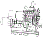
图1为本实施例的结构示意图;Fig. 1 is the structural representation of present embodiment;
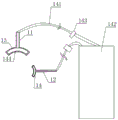
图2为本实施例的用于体现筛笼组件的结构示意图;Fig. 2 is a schematic structural diagram for embodying the screen cage assembly of the present embodiment;
图3为本实施例的用于体现第一物料清洗管的结构示意图;Fig. 3 is a schematic structural diagram for embodying the first material cleaning pipe in this embodiment;
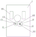
图4为本实施例的用于体现第二齿轮的结构示意图;Fig. 4 is a schematic structural diagram for embodying the second gear in this embodiment;
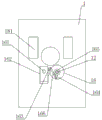
图5为本实施例的用于体现连杆的结构示意图;Fig. 5 is a schematic structural diagram for embodying the connecting rod in this embodiment;
图6是本实施例的用于体现导向块的结构示意图;Fig. 6 is a schematic structural diagram for embodying the guide block in this embodiment;
图7是本实施例的用于体现限位杆的结构示意图;Fig. 7 is a schematic structural diagram for embodying a limit rod in this embodiment;
图8是本实施例的用于体现加强板的结构示意图。Fig. 8 is a schematic structural diagram for embodying the reinforcing plate of this embodiment.
附图标记说明:Explanation of reference signs:
图中:1、物料仓;11、吸水管;12、第一物料清洗管;13、第一喷水板;14、第二喷水板;141、软管;142、蓄水槽;143、抽水泵;144、出水孔;15、移动孔;151、导向块;152、滑槽;16、第一齿轮;161、穿出孔;162、驱动板;163、第一摆杆;164、第二摆杆;165、驱动筒;166、连杆;167、电动机;17、第二物料清洗管;171、第二齿轮;172、连接孔;173、限位杆;18、封闭板;181、观察窗;19、底座;191、加强板;2、筛笼组件。Among the figure: 1, material bin; 11, water suction pipe; 12, first material cleaning pipe; 13, first water spray plate; 14, second water spray plate; 141, hose; 142, water storage tank; 143, pump Water pump; 144, water outlet hole; 15, moving hole; 151, guide block; 152, chute; 16, first gear; 161, piercing hole; 162, driving plate; Swing rod; 165, drive cylinder; 166, connecting rod; 167, motor; 17, second material cleaning pipe; 171, second gear; 172, connecting hole; 173, limit rod; 18, closing plate; 181, observation Window; 19, base; 191, reinforcement plate; 2, screen cage assembly.
实施方式Implementation
下面将结合本发明实施例中的附图,对本发明实施例中的技术方案进行清楚、完整地描述,显然,所描述的实施例仅仅是本发明一部分实施例,而不是全部的实施例。基于本发明中的实施例,本领域普通技术人员在没有做出创造性劳动前提下所获得的所有其他实施例,都属于本发明保护的范围。The following will clearly and completely describe the technical solutions in the embodiments of the present invention with reference to the accompanying drawings in the embodiments of the present invention. Obviously, the described embodiments are only some, not all, embodiments of the present invention. Based on the embodiments of the present invention, all other embodiments obtained by persons of ordinary skill in the art without making creative efforts belong to the protection scope of the present invention.
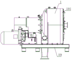
一种螺旋筛网离心机的带电动机的清洗机构,如图1和图2和图3,包括设置在物料仓1上的吸水管11以及设置在物料仓1上的且位于筛笼组件2内的第一物料清洗管12,吸水管11位于筛笼组件2上方,吸水管11的一端位于物料仓1内且设有与吸水管11连通的中空的第一喷水板13,第一喷水板13为弧形板,吸水管11的另一端位于物料仓1的上方,第一物料清洗管12的一端进入筛笼组件2内且在进入的一端设有中空的第二喷水板14,第二喷水板14为弧形板,第一物料清洗管12的另一端位于物料仓1的外壁,第一物料清洗管12和吸水管11在延伸出物料仓1的一端均通过软管141连通有蓄水槽142,软管141上设有抽水泵143,第一喷水板13和第二喷水板14在朝向筛笼组件2的一侧均开设有若干出水孔144,第一喷水板13和第二喷水板14可设置喷头与出水孔144连通。物料仓1和筛笼组件2的结构可以参考公告号为CN209271688U的中国专利公开的一种能够稳定运行过程的差速螺旋筛网离心机中的物料仓1和筛笼组件2的结构,为现有结构,因此在此不做赘述。此时第一物料清洗管12和吸水管11位于相互垂直的两个面上且一个位于筛笼组件2内,一个位于筛笼组件2上方。A cleaning mechanism with a motor of a spiral screen centrifuge, as shown in Figure 1 and Figure 2 and Figure 3, includes a
如图1和图2和图3,第一喷水板13和第二喷水板14的设置增大了吸水管11和第一物料清洗管12的喷射面积,提高了喷射到筛笼组件2上的冲洗面积,提高冲洗效率,抽水泵143通过软管141将蓄水槽142内的水吸到第一喷水板13和第二喷水板14上,吸水管11位于筛笼组件2上方,第一物料清洗管12的一端进入筛笼组件2内,此时便于第一喷水板13和第二喷水板14清洗筛笼组件2。As shown in Figure 1 and Figure 2 and Figure 3, the setting of the first
如图4和图6,第一物料清洗管12穿设在物料仓1上,物料仓1上开设有供第一物料清洗管12穿出的移动孔15,移动孔15的孔壁上设有导向块151,第一物料清洗管12外壁沿第一物料清洗管12长度方向开设有供导向块151滑移的滑槽152,物料仓1上设有推动第一物料清洗管12在移动孔15内往返移动的驱动件。As shown in Figure 4 and Figure 6, the first
如图4和图5,驱动件包括转动连接在物料仓1外壁的第一齿轮16,第一齿轮16与第一物料清洗管12同轴设置,且第一齿轮16中部开设有供第一物料清洗管12穿出的穿出孔161,第一物料清洗管12与穿出孔161螺纹连接,物料仓1外壁设有驱动第一齿轮16转动的第一带动件。第一带动件带动第一齿轮16转动时,第一齿轮16通过穿出孔161上的螺纹带动第一物料清洗管12向物料仓1内移动或者移出物料仓1。As shown in Fig. 4 and Fig. 5, the driving member includes a
如图4和图5,第一带动件包括设置在物料仓1上的L形驱动板162,驱动板162的水平边与物料仓1外壁连接,竖直边与物料仓1相对,驱动板162的竖直边与第一齿轮16错位分布,驱动板162的竖直边转动连接有第一摆杆163,第一齿轮16上设有第二摆杆164,第二摆杆164的一端设有与穿出孔161同轴的驱动筒165,驱动筒165沿穿出孔161边缘分布且固定在第一齿轮16上,第二摆杆164远离驱动筒165的一端铰接有连杆166,连杆166远离第二摆杆164的一端铰接在第一摆杆163上,驱动板162上设有驱动第一摆杆163转动的电动机167。As shown in Fig. 4 and Fig. 5, the first driving member includes an L-shaped
如图4和图5,电动机167带动第一摆杆163向远离第一齿轮16方向摆动时,第一摆杆163带动第二摆杆164摆动,通过第二摆杆164带动第一齿轮16转动,此时便于第一齿轮16带动第一物料清洗管12在物料仓1内移动。当电动机167带动第一摆杆163向靠近第一齿轮16方向摆动时,第一摆杆163带动第二摆杆164摆动,使得第二摆杆164带动第一齿轮16反向转动,便于第一齿轮16带动第一物料清洗管12反向移动。As shown in Figure 4 and Figure 5, when the
如图4和图5,物料仓1上在第一物料清洗管12的旁边平行设有第二物料清洗管17,第二物料清洗管17的一端延伸至筛笼组件2内,物料仓1上设有供第二物料清洗管17穿出的移出孔,第二物料清洗管17在移出孔内往复移动,物料仓1上设有驱动第二物料清洗管17移动的第二带动件。As shown in Fig. 4 and Fig. 5, a second
如图4和图5,第二带动件包括转动设置在物料仓1上的第二齿轮171,第二齿轮171与第一齿轮16啮合,第二齿轮171的直径小于第一齿轮16的直径,移出孔的孔壁上设有限位块,第二物料清洗管17上开设有供限位块往复移动的驱动槽,第二齿轮171上开设有供第二物料清洗管17同轴穿出的连接孔172,第二物料清洗管17与连接孔172的孔壁螺纹连接。As shown in Fig. 4 and Fig. 5, the second driving member includes a
如图4和图5,当第一齿轮16转动时,带动第二齿轮171转动,此时转动的第二齿轮171通过螺纹带动第二物料清洗管17在连接孔172内往复移动,进而改变了第二物料清洗管17在物料仓1内的位置,改变第二物料清洗管17在筛笼组件2内的一端的位置。As shown in Figures 4 and 5, when the
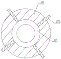
如图7,驱动筒165外壁螺纹连接有限位杆173,限位杆173穿过驱动筒165与第一物料清洗管12外壁抵触,限位杆173的数量为若干,且沿驱动筒165的周边均匀分布。当旋动限位杆173使得限位杆173一端抵触在第一物料清洗管12外壁时,限制了第一物料清洗管12的转动,此时电动机167停转时,使得第一物料清洗管12的位置被固定,根据需要选择第一物料清洗管12是否在筛笼组件2内移动。当电动机167工作时,可以将限位杆173从驱动筒165内旋出,进而便于第一物料清洗管12的移动。As shown in Figure 7, the outer wall of the
如图1和图2,物料仓1上端壁开设有安装孔,物料仓1上设有封闭安装孔的封闭板18,封闭板18通过螺栓与物料仓1上端壁连接,吸水管11设置在封闭板18上。此时便于打开封闭板18维修吸水管11。As shown in Figures 1 and 2, the upper end wall of the
如图4,物料仓1在设有第一物料清洗管12的一侧壁开设有观察窗181。观察窗181的设置便于观察第一物料清洗管12清洗筛笼组件2的情况。As shown in FIG. 4 , the
如图1和图8,清洗机构还包括底座19,物料仓1设置在底座19上,底座19上设有与物料仓1有第一物料清洗管12的一侧面平行的加强板191,第一物料清洗管12的一端穿出加强板191,驱动件设置在加强板191背离物料仓1的一侧面。此时加强板191的设置便于支撑第一物料清洗管12和第二物料清洗管17,第二物料清洗管17也穿出加强板191,此时观察窗181可以设置在加强板191上,同时物料仓1上也设置。As shown in Fig. 1 and Fig. 8, the cleaning mechanism also includes a
显然,本领域的技术人员可以对本发明进行各种改动和变型而不脱离本发明的精神和范围。这样,倘若本发明的这些修改和变型属于本发明权利要求及其等同技术的范围之内,则本发明也意图包含这些改动和变型在内。Obviously, those skilled in the art can make various changes and modifications to the present invention without departing from the spirit and scope of the present invention. Thus, if these modifications and variations of the present invention fall within the scope of the claims of the present invention and their equivalent technologies, the present invention also intends to include these modifications and variations.
Claims (10)
Priority Applications (1)
| Application Number | Priority Date | Filing Date | Title |
|---|---|---|---|
| CN202310072579.1A CN116328965B (en) | 2023-02-07 | 2023-02-07 | A cleaning mechanism with electric motor for spiral screen centrifuge |
Applications Claiming Priority (1)
| Application Number | Priority Date | Filing Date | Title |
|---|---|---|---|
| CN202310072579.1A CN116328965B (en) | 2023-02-07 | 2023-02-07 | A cleaning mechanism with electric motor for spiral screen centrifuge |
Publications (2)
| Publication Number | Publication Date |
|---|---|
| CN116328965A true CN116328965A (en) | 2023-06-27 |
| CN116328965B CN116328965B (en) | 2023-11-21 |
Family
ID=86884729
Family Applications (1)
| Application Number | Title | Priority Date | Filing Date |
|---|---|---|---|
| CN202310072579.1A Active CN116328965B (en) | 2023-02-07 | 2023-02-07 | A cleaning mechanism with electric motor for spiral screen centrifuge |
Country Status (1)
| Country | Link |
|---|---|
| CN (1) | CN116328965B (en) |
Cited By (1)
| Publication number | Priority date | Publication date | Assignee | Title |
|---|---|---|---|---|
| CN120815652A (en) * | 2025-09-15 | 2025-10-21 | 江苏蓝鸟离心机制造有限公司 | A new type of precession centrifuge |
Citations (9)
| Publication number | Priority date | Publication date | Assignee | Title |
|---|---|---|---|---|
| JPH0663155U (en) * | 1993-02-16 | 1994-09-06 | 日鉱金属株式会社 | centrifuge |
| CN108080157A (en) * | 2018-01-19 | 2018-05-29 | 蚌埠市朗辰化工设备有限公司 | A kind of uniform centrifuge of easy to clean and scraper |
| CN209271688U (en) * | 2018-12-27 | 2019-08-20 | 南京新筛分科技实业有限公司 | A kind of differential helical screens centrifuge for capableing of stable operation process |
| CN209465191U (en) * | 2019-01-29 | 2019-10-08 | 张家港市新华化工机械有限公司 | A kind of charging elution integrated device based on centrifuge |
| CN210496849U (en) * | 2019-06-24 | 2020-05-12 | 东营市永吉石油机械有限责任公司 | Centrifuge wiper mechanism |
| CN212349118U (en) * | 2020-04-01 | 2021-01-15 | 江苏科恩干燥科技有限公司 | High-rigidity low-vibration pusher centrifuge |
| CN212821417U (en) * | 2020-08-21 | 2021-03-30 | 荆州市普星生物科技股份有限公司 | High-efficient washing centrifuge |
| CN212976657U (en) * | 2020-07-29 | 2021-04-16 | 大连惠英机械有限公司 | Environment-friendly centrifugal casting device |
| CN215878349U (en) * | 2021-10-21 | 2022-02-22 | 烟台三生生物科技有限公司 | Centrifuge is used in preparation of disinfection bath |
-
2023
- 2023-02-07 CN CN202310072579.1A patent/CN116328965B/en active Active
Patent Citations (9)
| Publication number | Priority date | Publication date | Assignee | Title |
|---|---|---|---|---|
| JPH0663155U (en) * | 1993-02-16 | 1994-09-06 | 日鉱金属株式会社 | centrifuge |
| CN108080157A (en) * | 2018-01-19 | 2018-05-29 | 蚌埠市朗辰化工设备有限公司 | A kind of uniform centrifuge of easy to clean and scraper |
| CN209271688U (en) * | 2018-12-27 | 2019-08-20 | 南京新筛分科技实业有限公司 | A kind of differential helical screens centrifuge for capableing of stable operation process |
| CN209465191U (en) * | 2019-01-29 | 2019-10-08 | 张家港市新华化工机械有限公司 | A kind of charging elution integrated device based on centrifuge |
| CN210496849U (en) * | 2019-06-24 | 2020-05-12 | 东营市永吉石油机械有限责任公司 | Centrifuge wiper mechanism |
| CN212349118U (en) * | 2020-04-01 | 2021-01-15 | 江苏科恩干燥科技有限公司 | High-rigidity low-vibration pusher centrifuge |
| CN212976657U (en) * | 2020-07-29 | 2021-04-16 | 大连惠英机械有限公司 | Environment-friendly centrifugal casting device |
| CN212821417U (en) * | 2020-08-21 | 2021-03-30 | 荆州市普星生物科技股份有限公司 | High-efficient washing centrifuge |
| CN215878349U (en) * | 2021-10-21 | 2022-02-22 | 烟台三生生物科技有限公司 | Centrifuge is used in preparation of disinfection bath |
Cited By (2)
| Publication number | Priority date | Publication date | Assignee | Title |
|---|---|---|---|---|
| CN120815652A (en) * | 2025-09-15 | 2025-10-21 | 江苏蓝鸟离心机制造有限公司 | A new type of precession centrifuge |
| CN120815652B (en) * | 2025-09-15 | 2025-12-02 | 江苏蓝鸟离心机制造有限公司 | A new type of precession centrifuge |
Also Published As
| Publication number | Publication date |
|---|---|
| CN116328965B (en) | 2023-11-21 |
Similar Documents
| Publication | Publication Date | Title |
|---|---|---|
| CN213376149U (en) | Air flow conveying device for feeding of coating mixing tank | |
| CN218796484U (en) | A sorting and washing device | |
| CN118122420A (en) | Dust-less stone breaking device for building construction | |
| CN116328965B (en) | A cleaning mechanism with electric motor for spiral screen centrifuge | |
| CN115364999A (en) | A high-efficient type cylinder log washer that is used for mineral products to open to produce and has water conservation function | |
| CN111151408A (en) | A powder spraying recovery device | |
| CN112264298A (en) | Prevent husky equipment of sieve of stifled | |
| CN218713449U (en) | Lifting type river sludge cleaning machine | |
| CN207872679U (en) | Supersonic wave cleaning machine | |
| CN216500553U (en) | Prevent cylinder sieve separator of putty | |
| CN116902501A (en) | Anti-blocking structure for sludge treatment | |
| CN221232369U (en) | Drum-type shot blasting machine | |
| CN211051886U (en) | Drum screen with self-cleaning function | |
| CN209866809U (en) | Sand washing machine | |
| CN220844245U (en) | Cherry processing material feeding unit | |
| CN219923844U (en) | A silicon material cleaning and screening device | |
| CN221908325U (en) | A pretreatment device for preparing building materials that is easy to load | |
| CN207120473U (en) | Back flush automatically cleaning continuous filter | |
| CN223628979U (en) | A coal screening and cleaning device | |
| CN221700146U (en) | A flexible and anti-clogging K-type coal feeder | |
| CN220950275U (en) | Rotary discharger for cement production and processing | |
| CN221391751U (en) | Raw material sorting device | |
| CN218478097U (en) | Screw conveyer with cutting and scattering functions | |
| CN216988491U (en) | Novel ore dressing is with high-efficient drum sieve | |
| CN222729734U (en) | Extractor for cottonseed production and processing |
Legal Events
| Date | Code | Title | Description |
|---|---|---|---|
| PB01 | Publication | ||
| PB01 | Publication | ||
| SE01 | Entry into force of request for substantive examination | ||
| SE01 | Entry into force of request for substantive examination | ||
| GR01 | Patent grant | ||
| GR01 | Patent grant | ||
| PE01 | Entry into force of the registration of the contract for pledge of patent right | ||
| PE01 | Entry into force of the registration of the contract for pledge of patent right |
Denomination of invention: A cleaning mechanism with an electric motor for a spiral screen centrifuge Effective date of registration: 20231220 Granted publication date: 20231121 Pledgee: Nanjing Bank Co.,Ltd. Nanjing North Branch Pledgor: NANJING CHINASIEVING TECHNOLOGY INDUSTRIAL CO.,LTD. Registration number: Y2023980072674 |
|
| PC01 | Cancellation of the registration of the contract for pledge of patent right | ||
| PC01 | Cancellation of the registration of the contract for pledge of patent right |
Granted publication date: 20231121 Pledgee: Nanjing Bank Co.,Ltd. Nanjing North Branch Pledgor: NANJING CHINASIEVING TECHNOLOGY INDUSTRIAL CO.,LTD. Registration number: Y2023980072674 |