CN116291667A - Tunnel reversing ventilation device - Google Patents
Tunnel reversing ventilation device Download PDFInfo
- Publication number
- CN116291667A CN116291667A CN202310346461.3A CN202310346461A CN116291667A CN 116291667 A CN116291667 A CN 116291667A CN 202310346461 A CN202310346461 A CN 202310346461A CN 116291667 A CN116291667 A CN 116291667A
- Authority
- CN
- China
- Prior art keywords
- adjusting
- self
- filter
- cleaning filter
- seat
- Prior art date
- Legal status (The legal status is an assumption and is not a legal conclusion. Google has not performed a legal analysis and makes no representation as to the accuracy of the status listed.)
- Pending
Links
Images




Classifications
-
- E—FIXED CONSTRUCTIONS
- E21—EARTH OR ROCK DRILLING; MINING
- E21F—SAFETY DEVICES, TRANSPORT, FILLING-UP, RESCUE, VENTILATION, OR DRAINING IN OR OF MINES OR TUNNELS
- E21F1/00—Ventilation of mines or tunnels; Distribution of ventilating currents
- E21F1/006—Ventilation at the working face of galleries or tunnels
-
- A—HUMAN NECESSITIES
- A61—MEDICAL OR VETERINARY SCIENCE; HYGIENE
- A61L—METHODS OR APPARATUS FOR STERILISING MATERIALS OR OBJECTS IN GENERAL; DISINFECTION, STERILISATION OR DEODORISATION OF AIR; CHEMICAL ASPECTS OF BANDAGES, DRESSINGS, ABSORBENT PADS OR SURGICAL ARTICLES; MATERIALS FOR BANDAGES, DRESSINGS, ABSORBENT PADS OR SURGICAL ARTICLES
- A61L2/00—Disinfection or sterilisation of materials or objects, in general; Accessories therefor
- A61L2/02—Disinfection or sterilisation of materials or objects, in general; Accessories therefor using physical processes
- A61L2/025—Ultrasonic waves
-
- A—HUMAN NECESSITIES
- A61—MEDICAL OR VETERINARY SCIENCE; HYGIENE
- A61L—METHODS OR APPARATUS FOR STERILISING MATERIALS OR OBJECTS IN GENERAL; DISINFECTION, STERILISATION OR DEODORISATION OF AIR; CHEMICAL ASPECTS OF BANDAGES, DRESSINGS, ABSORBENT PADS OR SURGICAL ARTICLES; MATERIALS FOR BANDAGES, DRESSINGS, ABSORBENT PADS OR SURGICAL ARTICLES
- A61L2/00—Disinfection or sterilisation of materials or objects, in general; Accessories therefor
- A61L2/02—Disinfection or sterilisation of materials or objects, in general; Accessories therefor using physical processes
- A61L2/04—Heat
-
- A—HUMAN NECESSITIES
- A61—MEDICAL OR VETERINARY SCIENCE; HYGIENE
- A61L—METHODS OR APPARATUS FOR STERILISING MATERIALS OR OBJECTS IN GENERAL; DISINFECTION, STERILISATION OR DEODORISATION OF AIR; CHEMICAL ASPECTS OF BANDAGES, DRESSINGS, ABSORBENT PADS OR SURGICAL ARTICLES; MATERIALS FOR BANDAGES, DRESSINGS, ABSORBENT PADS OR SURGICAL ARTICLES
- A61L2/00—Disinfection or sterilisation of materials or objects, in general; Accessories therefor
- A61L2/02—Disinfection or sterilisation of materials or objects, in general; Accessories therefor using physical processes
- A61L2/08—Radiation
- A61L2/10—Ultraviolet [UV] radiation
-
- A—HUMAN NECESSITIES
- A61—MEDICAL OR VETERINARY SCIENCE; HYGIENE
- A61L—METHODS OR APPARATUS FOR STERILISING MATERIALS OR OBJECTS IN GENERAL; DISINFECTION, STERILISATION OR DEODORISATION OF AIR; CHEMICAL ASPECTS OF BANDAGES, DRESSINGS, ABSORBENT PADS OR SURGICAL ARTICLES; MATERIALS FOR BANDAGES, DRESSINGS, ABSORBENT PADS OR SURGICAL ARTICLES
- A61L2/00—Disinfection or sterilisation of materials or objects, in general; Accessories therefor
- A61L2/26—Accessories
-
- B—PERFORMING OPERATIONS; TRANSPORTING
- B01—PHYSICAL OR CHEMICAL PROCESSES OR APPARATUS IN GENERAL
- B01D—SEPARATION
- B01D46/00—Filters or filtering processes specially modified for separating dispersed particles from gases or vapours
- B01D46/10—Particle separators, e.g. dust precipitators, using filter plates, sheets or pads having plane surfaces
-
- B—PERFORMING OPERATIONS; TRANSPORTING
- B01—PHYSICAL OR CHEMICAL PROCESSES OR APPARATUS IN GENERAL
- B01D—SEPARATION
- B01D46/00—Filters or filtering processes specially modified for separating dispersed particles from gases or vapours
- B01D46/66—Regeneration of the filtering material or filter elements inside the filter
-
- E—FIXED CONSTRUCTIONS
- E21—EARTH OR ROCK DRILLING; MINING
- E21F—SAFETY DEVICES, TRANSPORT, FILLING-UP, RESCUE, VENTILATION, OR DRAINING IN OR OF MINES OR TUNNELS
- E21F1/00—Ventilation of mines or tunnels; Distribution of ventilating currents
- E21F1/08—Ventilation arrangements in connection with air ducts, e.g. arrangements for mounting ventilators
-
- Y—GENERAL TAGGING OF NEW TECHNOLOGICAL DEVELOPMENTS; GENERAL TAGGING OF CROSS-SECTIONAL TECHNOLOGIES SPANNING OVER SEVERAL SECTIONS OF THE IPC; TECHNICAL SUBJECTS COVERED BY FORMER USPC CROSS-REFERENCE ART COLLECTIONS [XRACs] AND DIGESTS
- Y02—TECHNOLOGIES OR APPLICATIONS FOR MITIGATION OR ADAPTATION AGAINST CLIMATE CHANGE
- Y02B—CLIMATE CHANGE MITIGATION TECHNOLOGIES RELATED TO BUILDINGS, e.g. HOUSING, HOUSE APPLIANCES OR RELATED END-USER APPLICATIONS
- Y02B30/00—Energy efficient heating, ventilation or air conditioning [HVAC]
- Y02B30/70—Efficient control or regulation technologies, e.g. for control of refrigerant flow, motor or heating
Landscapes
- Health & Medical Sciences (AREA)
- Life Sciences & Earth Sciences (AREA)
- General Health & Medical Sciences (AREA)
- Mining & Mineral Resources (AREA)
- Epidemiology (AREA)
- Animal Behavior & Ethology (AREA)
- Engineering & Computer Science (AREA)
- Public Health (AREA)
- Veterinary Medicine (AREA)
- General Life Sciences & Earth Sciences (AREA)
- Geochemistry & Mineralogy (AREA)
- Geology (AREA)
- Chemical & Material Sciences (AREA)
- Chemical Kinetics & Catalysis (AREA)
- Filtering Of Dispersed Particles In Gases (AREA)
Abstract
The invention discloses a tunnel reversing ventilation device, which belongs to the technical field of tunnels and solves the problem that an air conveying pipe of the conventional ventilation device cannot purify and filter sucked or exhausted air, so that the conveying pipe cannot meet the tunnel reversing ventilation requirement, and comprises: the detachable reversing ventilation main body comprises a diversion shell and a purification shell; the flow guiding shell is provided with a flow guiding opening, the purifying shell is provided with a purifying opening, and the flow guiding shell and the purifying shell are surrounded to form a reversing ventilation cavity; the self-cleaning filter assembly is used for bidirectional filtering and purifying of the gas in the reversing ventilation cavity and is fixedly arranged in the purifying shell; be provided with self-cleaning filter part, filter linkage portion and prevent blockking up portion in this application, filter linkage portion can also drive and prevent blockking up portion and self-cleaning filter part motion, guaranteed self-cleaning filter part's filtration efficiency, can also avoid piling up of dust and dirt on the self-cleaning filter part.
Description
Technical Field
The invention belongs to the technical field of tunnels, and particularly relates to a tunnel reversing ventilation device.
Background
In order to ensure the safety, quality and efficiency of tunnel construction and the physical and psychological health of operators, creating a good construction operation environment becomes important for all parties, the effect of ventilation in tunnel construction is more important, and the difficulty of ventilation in construction is also increased.
Chinese patent CN210460727U discloses a tunnel ventilation device, the tunnel ventilation device includes the tunnel body, be provided with singlechip, division board, exhaust column, air delivery window and air delivery pipe on the tunnel body, the singlechip pass through the rivet with the inside upper wall of tunnel body is connected, the division board pass through the rivet with the inside top of tunnel body is connected, the exhaust column pass through the rivet with the inside of tunnel body is connected, and be located the top of division board, the air delivery window pass through the rivet with the inside left and right sides of tunnel body is connected, the air delivery pipe is located the inboard of air delivery window, the lower extreme of exhaust column is provided with the suction head, be provided with conveyer pipe and exhaust head on the air delivery pipe; however, the air delivery pipe of the existing ventilation device cannot purify and filter the sucked or exhausted air, so that the delivery pipe cannot meet the tunnel reversing ventilation requirement, and based on the tunnel reversing ventilation device, we propose a tunnel reversing ventilation device.
Disclosure of Invention
The invention aims to overcome the defects of the prior art, and provides a tunnel reversing ventilation device, which solves the problem that an air conveying pipe of the prior ventilation device cannot purify and filter sucked or discharged air, so that the conveying pipe cannot meet the tunnel reversing ventilation requirement.
The current ventilation unit air duct can not carry out purification filtration to the inhaled or exhaust air to make the conveyer pipe unable to satisfy tunnel switching-over ventilation demand, based on this, we have provided a tunnel switching-over ventilation unit. Briefly, the tunnel reversing ventilation device includes: the detachable reversing ventilation main body comprises a diversion shell and a purification shell; the guide shell is provided with a guide opening, the purification shell is provided with a purification opening, the guide shell and the purification shell are surrounded to form a reversing ventilation cavity, and an exhaust fan is fixedly arranged in the reversing ventilation cavity; the self-cleaning filter assembly is used for bidirectional filtering and purifying of the gas in the reversing ventilation cavity and is fixedly arranged in the purifying shell; the self-cleaning filter assembly comprises a self-cleaning filter seat, a rotatable self-cleaning filter part, a filter linkage part and an anti-blocking part.
The invention is realized in that a tunnel reversing ventilation device comprises:
the detachable reversing ventilation main body comprises a diversion shell and a purification shell;
wherein, the diversion shell is provided with a diversion port, the purification shell is provided with a purification port, the diversion shell and the purification shell are surrounded to form a reversing ventilation cavity, and an exhaust fan is fixedly arranged in the reversing ventilation cavity;
the self-cleaning filter assembly is used for bidirectional filtering and purifying of the gas in the reversing ventilation cavity and is fixedly arranged in the purifying shell;
the self-cleaning filter assembly comprises a self-cleaning filter seat, a rotatable self-cleaning filter part, a filter linkage part and an anti-blocking part, wherein the self-cleaning filter seat is detachably arranged in a purification shell, the self-cleaning filter part is used for filtering and purifying gas in a reversing ventilation cavity, and the self-cleaning filter part and the anti-blocking part are respectively connected with the filter linkage part.
Preferably, the filtering linkage includes:
the filter driving piece is fixedly arranged in the self-cleaning filter seat;
the filter driving piece is fixedly connected with the filter driving piece, and one end of the filter driving piece is detachably and fixedly connected with the self-cleaning filter part;
the filter sleeving part is sleeved on the filter transmission part;
the filter follower, the filter follower sets up one side of establishing the piece is established to the filter, and the one end fixedly connected with of filter follower prevent blockking up the portion.
Preferably, the self-cleaning filter section comprises:
one side of the self-cleaning filter plate is fixedly connected with the filtering transmission piece;
at least one group of self-cleaning filter holes, which are used for purifying and filtering the air in the reversing ventilation cavity.
Preferably, the anti-clogging portion includes:
the anti-blocking seat is fixedly arranged in the purifying shell;
the anti-blocking push plate is slidably arranged in the anti-blocking seat, one side of the anti-blocking push plate is fixedly connected with the filtering driven piece, and
and the dust blowing-off pipes are arranged in the anti-blocking seat and are used for blowing off dust accumulated on the surface of the self-cleaning filter plate.
Preferably, the air conditioner further comprises an adjusting and guiding mechanism for adjusting the air outlet flow, the adjusting and guiding mechanism is installed in the guiding shell, and the adjusting and guiding mechanism comprises:
the guide bearing seat is detachably arranged in the guide shell;
at least one group of adjusting guide parts, wherein the adjusting guide parts are rotationally connected with the guide bearing bracket;
the adjusting driving assembly is arranged in the guide bearing seat and is used for adjusting the inclination angle of the adjusting guide part.
Preferably, the adjustment drive assembly comprises:
an adjustment drive mounted within the flow-directing socket;
the adjusting pushing piece is fixedly connected with the adjusting driving part and is used for pushing the adjusting diversion part to swing so as to realize the adjustment of the air outlet flow;
the adjusting limiting seat is slidably mounted in the guide shell, and one end of the adjusting limiting seat is connected with the adjusting driving part and used for limiting the adjusting pushing piece.
Preferably, the adjustment driving part includes:
the adjusting driving piece is fixedly arranged in the flow guide bearing seat;
the adjusting transmission part is fixedly connected with the adjusting driving part;
the adjusting sleeve is sleeved on the adjusting transmission part, the adjusting sleeve is fixedly connected with the adjusting pushing part, and one end, far away from the adjusting sleeve, of the adjusting pushing part is detachably and fixedly connected with the pushing buffer part.
Preferably, the adjusting guide part includes:
the flow guide connecting plate is rotatably arranged in the flow guide bearing seat through a rotating shaft;
and the adjusting guide plate is detachably connected with the guide connecting plate and is used for guiding the discharged airflow.
Preferably, the adjusting guide part further includes:
the guide disinfection seat is fixedly arranged at the end part of the adjusting guide plate, and a guide disinfection component for disinfecting and purifying the discharged air is arranged in the guide disinfection seat.
Preferably, the diversion sterilization assembly comprises:
the first disinfection part is embedded in the diversion disinfection seat and is used for disinfecting and purifying air flowing through the diversion disinfection seat;
and the second disinfection part is detachably arranged in the diversion disinfection seat and is also used for disinfecting and purifying air flowing through the diversion disinfection seat.
Compared with the prior art, the embodiment of the application has the following main beneficial effects:
be provided with self-cleaning filter part, filter linkage portion and prevent blockking up portion in this application, filter linkage portion can also drive and prevent blockking up portion and self-cleaning filter part motion, guaranteed self-cleaning filter part's filtration efficiency, can also avoid piling up of dust and dirt on the self-cleaning filter part, can provide clean sterile air when tunnel construction, avoid the emergence of accident.
Drawings
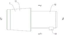
Fig. 1 is a schematic structural diagram of a tunnel reversing ventilation device provided by the invention.
Fig. 2 is an isometric view of the present invention.
Fig. 3 is a front view of the present invention.
Fig. 4 is a cross-sectional view taken along A-A of fig. 3.
Fig. 5 is a B-B cross-sectional view of fig. 3.
FIG. 6 is a schematic structural view of a self-cleaning filter assembly provided by the present invention.
FIG. 7 is an isometric view of a self-cleaning filter assembly provided by the present invention.
Fig. 8 is a schematic structural diagram of an adjusting and guiding mechanism provided by the invention.
Fig. 9 is an isometric view of an adjustable deflector mechanism provided by the present invention.
Fig. 10 is a front view of the adjustable deflector mechanism provided by the present invention.
Fig. 11 is a left side view of the adjustable deflector mechanism provided by the present invention.
Fig. 12 is a right side view of the adjustable deflector mechanism provided by the present invention.
Fig. 13 is a top view of an adjustable deflector mechanism provided by the present invention.
In the figure: 1-reversing ventilation main body, 11-diversion shell, 111-diversion through opening, 12-purifying shell, 121-purifying through opening, 13-exhaust fan, 14-reversing ventilation cavity, 2-self-cleaning filter component, 21-self-cleaning filter seat, 22-self-cleaning filter part, 221-self-cleaning filter plate, 222-self-cleaning filter hole, 23-filtering linkage part, 231-filtering driving part, 232-filtering driving part, 233-filtering sleeve part, 234-filtering driven part, 24-anti-blocking part, 241-anti-blocking seat, 242-dust blowing pipe, 243-anti-blocking push plate, 3-adjusting diversion mechanism, 31-diversion supporting seat, 32-adjusting driving part, 321-adjusting driving part, 322-adjusting driving part, 323-adjusting sleeve part, 33-adjusting limiting seat, 34-adjusting pushing part, 341-pushing buffer part, 35-adjusting diversion part, 351-adjusting diversion plate, 352-diversion sterilizing seat, 353-diversion connecting plate, 36-guiding component, 361-first sterilizing part and 362-second sterilizing part.
Detailed Description
Unless defined otherwise, all technical and scientific terms used herein have the same meaning as commonly understood by one of ordinary skill in the art to which this application belongs; the terminology used in the description of the applications herein is for the purpose of describing particular embodiments only and is not intended to be limiting of the application; the terms "comprising" and "having" and any variations thereof in the description and claims of the present application and in the description of the figures above are intended to cover non-exclusive inclusions. The terms first, second and the like in the description and in the claims or in the above-described figures, are used for distinguishing between different objects and not necessarily for describing a sequential or chronological order.
Reference herein to "an embodiment" means that a particular feature, structure, or characteristic described in connection with the embodiment may be included in at least one embodiment of the present application. The appearances of such phrases in various places in the specification are not necessarily all referring to the same embodiment, nor are separate or alternative embodiments mutually exclusive of other embodiments. Those of skill in the art will explicitly and implicitly appreciate that the embodiments described herein may be combined with other embodiments.
In order to ensure the safety, quality and efficiency of tunnel construction and the physical and psychological health of operators, creating a good construction operation environment becomes important for all parties, the effect of tunnel construction ventilation is more important, the difficulty of the construction ventilation is greater and greater, but the air conveying pipe of the conventional ventilation device cannot purify and filter sucked or discharged air, so that the conveying pipe cannot meet the requirement of tunnel reversing ventilation, and based on the tunnel reversing ventilation device, the tunnel reversing ventilation device is provided.
Briefly, the tunnel reversing ventilation device includes: a detachable reversing ventilation main body 1, wherein the reversing ventilation main body 1 comprises a diversion shell 11 and a purification shell 12; the diversion shell 11 is provided with a diversion port 111, the purification shell 12 is provided with a purification port 121, the diversion shell 11 and the purification shell 12 are surrounded to form a reversing ventilation cavity 14, and an exhaust fan 13 is fixedly arranged in the reversing ventilation cavity 14; the self-cleaning filter assembly 2 is used for filtering and purifying the gas in the reversing ventilation cavity 14 in a two-way manner, and the self-cleaning filter assembly 2 is fixedly arranged in the purifying shell 12; the self-cleaning filter assembly 2 includes a self-cleaning filter base 21, a rotatable self-cleaning filter portion 22, a filter linkage portion 23, and an anti-clogging portion 24. When the self-cleaning filter is operated, the exhaust fan 13 arranged in the reversing ventilation cavity 14 is started, the exhaust fan 13 pumps outside air or dirty air in a tunnel into the reversing ventilation cavity 14, the self-cleaning filter part 22 can filter and purify air flowing in from different directions, so that the cleanness of exhaust gas is ensured, the purification ventilation of tunnel construction is facilitated, meanwhile, when the wind direction is changed, the filter linkage part 23 is started, the filter linkage part 23 can drive the self-cleaning filter part 22 to rotate, so that the filtering efficiency of the self-cleaning filter part 22 is ensured, and meanwhile, the filter linkage part 23 can also drive the anti-blocking part 24 to start, so that the accumulation of dust and dirt on the self-cleaning filter part 22 is avoided, and the purification efficiency of the self-cleaning filter part 22 is further improved. Be provided with self-cleaning filter part 22 in this application, filter linkage part 23 and prevent blockking up portion 24, filter linkage part 23 can also drive prevent blockking up portion 24 and self-cleaning filter part 22 motion, guaranteed self-cleaning filter part 22's filtration efficiency, can also avoid self-cleaning filter part 22 to go up the accumulation of dust and dirt, can provide clean sterile air when tunnel construction, avoid the emergence of accident.
The embodiment of the invention provides a tunnel reversing ventilation device, as shown in fig. 1-5, which comprises:
a detachable reversing ventilation body 1, wherein the reversing ventilation body 1 comprises a diversion shell 11 and a purification shell 12;
the guiding shell 11 is provided with a guiding port 111, the purifying shell 12 is provided with a purifying port 121, the guiding shell 11 and the purifying shell 12 are surrounded to form a reversing ventilation cavity 14, and an exhaust fan 13 is fixedly arranged in the reversing ventilation cavity 14.
It should be noted that, the guiding shell 11 and the purifying shell 12 may be hollow cylinder or rectangular seat structures, and in order to ensure the strength of the guiding shell 11 and the purifying shell 12, the guiding shell 11 and the purifying shell 12 may be made of carbon steel or titanium alloy, so that deformation during tunnel operation can be avoided, normal operation of reversing ventilation during tunnel operation can be ensured, and meanwhile, the inner diameter of the guiding shell 11 may be larger than the inner diameter of the purifying shell 12, so that air exhaust amount and air exhaust direction can be conveniently adjusted.
The flow guiding through hole 111 and the purifying through hole 121 in the present application may be rectangular grooves, round grooves or polygonal grooves, and the flow guiding through hole 111 and the purifying through hole 121 may be used as air outlets/air inlets, so that the present application has the function of reversing ventilation, and the application range of the present application is further enlarged.
The exhaust fan 13 may be fixedly installed in the diversion housing 11 or the purification housing 12 by fastening bolts or welding, and meanwhile, the exhaust fan 13 is an axial flow fan, the shaft power of which is 0.12kw, and the rotation speed of which is 3500 r/mm.
The self-cleaning filter assembly 2 is used for filtering and purifying the gas in the reversing ventilation cavity 14 in a two-way manner, and the self-cleaning filter assembly 2 is fixedly arranged in the purifying shell 12;
the self-cleaning filter assembly 2 comprises a self-cleaning filter seat 21, a rotatable self-cleaning filter part 22, a filter linkage part 23 and an anti-blocking part 24, wherein the self-cleaning filter seat 21 is detachably arranged in the purification shell 12, the self-cleaning filter part 22 is used for filtering and purifying gas in the reversing ventilation cavity 14, and the self-cleaning filter part 22 and the anti-blocking part 24 are respectively connected with the filter linkage part 23.
In this embodiment, when working, the exhaust fan 13 installed in the reversing ventilation cavity 14 is opened, the exhaust fan 13 pumps the external air or the dirty air in the tunnel into the reversing ventilation cavity 14, the self-cleaning filter part 22 can filter and purify the air flowing in from different directions, so that the cleanness of the exhaust gas is ensured, the purification ventilation of the tunnel construction is facilitated, meanwhile, when the wind direction is changed, the filter linkage part 23 is opened, the filter linkage part 23 can drive the self-cleaning filter part 22 to rotate, so that the filtering efficiency of the self-cleaning filter part 22 is ensured, and meanwhile, the filter linkage part 23 can also drive the anti-blocking part 24 to start, so that the accumulation of dust and dirt on the self-cleaning filter part 22 is avoided, and the purifying efficiency of the self-cleaning filter part 22 is further improved.
Be provided with self-cleaning filter part 22 in this application, filter linkage part 23 and prevent blockking up portion 24, filter linkage part 23 can also drive prevent blockking up portion 24 and self-cleaning filter part 22 motion, guaranteed self-cleaning filter part 22's filtration efficiency, can also avoid self-cleaning filter part 22 to go up the accumulation of dust and dirt, can provide clean sterile air when tunnel construction, avoid the emergence of accident.
In a further preferred embodiment of the present invention, as shown in fig. 6 to 7, the filtering linkage 23 includes:
a filter drive 231, the filter drive 231 being fixedly mounted within the self-cleaning filter base 21;
a filter driving member 232 fixedly connected with the filter driving member 231, wherein one end of the filter driving member 232 is detachably and fixedly connected with the self-cleaning filter part 22;
a filter sleeve 233 sleeved on the filter driving member 232;
the filter follower 234, the filter follower 234 is disposed at one side of the filter sleeve 233, and one end of the filter follower 234 is fixedly connected with the anti-blocking portion 24.
In this embodiment, the filter driving member 231 may be a servo motor, the filter driving member 231 is fixedly mounted in the self-cleaning filter seat 21 through a clamp or a fastening bolt, the filter driving member 231 is connected with the filter driving member 232 in an interference fit manner, the filter driving member 232 may be a rotating shaft or a driving rod, the filter sleeving member 233 may be a gear, the filter sleeving member 233 and the filter driven member 234 are in meshed transmission, the filter driven member 234 is specifically a hollow rack longitudinally arranged, a hollow groove is formed in the middle of the hollow rack, a positioning block is embedded in the hollow groove, the positioning block is in sliding connection with the hollow groove, and the positioning block can be fixedly connected with the self-cleaning filter seat 21 or the purifying shell 12 through a connecting rod.
When the self-cleaning filter is in operation, the filter driving piece 231 is started, the filter driving piece 231 can drive the filter driving piece 232 to rotate, and the filter driving piece 232 drives the filter sleeving piece 233 to rotate, so that the filter sleeving piece 233 drives the filter driven piece 234 to move up and down, the function of driving the anti-blocking part 24 is achieved, the blocking of the self-cleaning filter part 22 is avoided, and the purification efficiency of the self-cleaning filter part 22 is ensured.
In a further preferred embodiment of the present invention, as shown in FIGS. 6-7, the self-cleaning filter section 22 comprises:
a self-cleaning filter plate 221, wherein one side of the self-cleaning filter plate 221 is fixedly connected with a filter transmission member 232;
at least one set of self-cleaning filter apertures 222, the self-cleaning filter apertures 222 for purifying and filtering air within the reversing ventilation chamber 14.
In this embodiment, the self-cleaning filter plate 221 may be an incomplete circular plate or a rectangular plate, and the self-cleaning filter holes 222 may be filled with filter membranes or activated carbon particles, and the self-cleaning filter holes 222 may be circumferentially or matrix distributed on the self-cleaning filter plate 221.
In a further preferred embodiment of the present invention, as shown in fig. 6 to 7, the anti-clogging portion 24 includes:
an anti-clogging seat 241, the anti-clogging seat 241 being fixedly installed in the purification housing 12;
an anti-clogging push plate 243 slidably mounted in the anti-clogging seat 241, fixedly connected between one side of the anti-clogging push plate 243 and the filter follower 234, and
at least one set of dust blowing pipes 242, said dust blowing pipes 242 being installed in said anti-clogging base 241 for blowing off dust accumulated on the surface of said self-cleaning filter plate 221.
In this embodiment, the anti-blocking seat 241 may be a hollow round seat or a rectangular seat, and the anti-blocking seat 241 is fixedly mounted in the purification casing 12 by fastening bolts or a seamless welding manner, meanwhile, the anti-blocking push plate 243 may be a rectangular seat or a round seat, the edge of the anti-blocking seat is polished, the dust blowing pipes 242 are uniformly distributed on one side of the anti-blocking seat 241, the dust blowing pipes 242 are obliquely arranged, and the dust blowing pipes 242 are communicated with the anti-blocking seat 241 in a penetrating manner.
During operation, the filtering follower 234 moves up and down to push the anti-blocking push plate 243 to move up and down, so that air in the anti-blocking seat 241 is intermittently compressed to enter the dust blowing pipe 242, the purpose of blowing off dust and dirt on the self-cleaning filter plate 221 is achieved, and meanwhile, one side of the anti-blocking seat 241 is communicated with the reversing ventilation cavity 14 in a penetrating manner through the flow guide pipe.
In a further preferred embodiment of the present invention, as shown in fig. 8-13, the embodiment of the present invention further includes an adjusting and guiding mechanism 3 for adjusting the flow of the air out, the adjusting and guiding mechanism 3 is installed in the guiding housing 11, and the adjusting and guiding mechanism 3 includes:
a guide socket 31, wherein the guide socket 31 is detachably installed in the guide shell 11;
at least one group of adjusting guide parts 35, wherein the adjusting guide parts 35 are rotationally connected with the guide bearing bracket 31;
the adjusting driving assembly is arranged in the diversion bearing bracket 31 and is used for adjusting the inclination angle of the diversion adjusting part 35.
In this embodiment, the air guiding support seat 31 may be a rectangular seat or a round seat with a hollow interior, and the air guiding support seat 31 may be detachably mounted in the air guiding housing 11 through a buckle, and when in operation, the adjusting driving assembly is started, and the adjusting driving assembly can drive the adjusting air guiding portion 35 to swing, so that the air outlet amount is adjusted, and the air guiding can be realized.
In a further preferred embodiment of the present invention, as shown in fig. 8-10, the adjustment drive assembly comprises:
an adjustment drive portion 32, the adjustment drive portion 32 being mounted within the flow guide socket 31;
the adjusting pushing piece 34 is fixedly connected with the adjusting driving part 32, and the adjusting pushing piece 34 is used for pushing the adjusting guide part 35 to swing so as to realize the adjustment of the air outlet flow;
the adjusting and limiting seat 33 is slidably mounted in the diversion shell 11, and one end of the adjusting and limiting seat 33 is connected with the adjusting and driving part 32 and used for limiting the adjusting and pushing piece 34.
In this embodiment, the adjusting driving part 32 can drive the adjusting pushing member 34 to move horizontally, so that the adjusting pushing member 34 pushes the adjusting guiding part 35 to swing, thereby realizing the adjustment of the air output, and meanwhile, the adjusting limiting seat 33 can limit the adjusting pushing member 34, so that the stable operation of the adjusting pushing member 34 is ensured.
In a further preferred embodiment of the present invention, as shown in fig. 8-13, the adjustment driving part 32 includes:
an adjustment driving member 321, wherein the adjustment driving member 321 is fixedly arranged in the diversion bearing bracket 31;
an adjustment transmission member 322 fixedly connected to the adjustment driving member 321;
the adjusting sleeve member 323 sleeved on the adjusting transmission member 322 is fixedly connected with the adjusting pushing member 34, and one end, away from the adjusting sleeve member 323, of the adjusting pushing member 34 is detachably and fixedly connected with the pushing buffer portion 341.
In this embodiment, the adjusting driving member 321 may be a servo motor, the adjusting driving member 321 may be fixedly mounted in the guide bearing seat 31 through a clamp or a fastening bolt, the adjusting driving member 322 may be a threaded rod, the adjusting driving member 322 is in threaded connection with the adjusting sleeve member 323, the adjusting sleeve member 323 may be an internal threaded ring or an internal threaded sleeve, the adjusting sleeve member 323 is fixedly connected with the adjusting pushing member 34 through a fastening bolt or a buckle, the adjusting pushing member 34 may be two groups, three groups or four groups, the adjusting pushing member 34 is specifically a round rod or a rectangular rod, the pushing buffer portion 341 may be a damping spring, a hydraulic telescopic rod or a spring telescopic rod, and the telescopic end of the pushing buffer portion 341 is in abutting connection with the adjusting guide portion 35, thereby facilitating adjustment of the swinging angle of the adjusting guide portion 35.
In a further preferred embodiment of the present invention, as shown in fig. 8-13, the adjusting guide 35 includes:
the guide connection plate 353 is rotatably arranged in the guide bearing bracket 31 through a rotating shaft;
an adjusting deflector 351 detachably connected to the deflector connection plate 353, the adjusting deflector 351 being used for deflecting the exhaust air flow.
The guide disinfection seat 352 is fixedly installed at the end part of the adjusting guide plate 351, and a guide disinfection assembly 36 for disinfecting and purifying the discharged air is arranged in the guide disinfection seat 352.
Illustratively, the flow guiding connection plate 353 is specifically an arc plate or a rectangular plate which is obliquely arranged, the flow guiding connection plate 353 is detachably connected with the adjusting flow guiding plate 351 through bolts, the adjusting flow guiding plate 351 can be an arc plate or a semicircular plate, the inner wall of the adjusting flow guiding plate 351 is polished, wind resistance can be effectively reduced, the flow guiding disinfection seat 352 can be a fan plate or a rectangular plate, and the flow guiding disinfection assembly 36 can sufficiently disinfect and purify air entering the reversing ventilation cavity 14, so that the construction environment of a tunnel is further ensured.
In this embodiment, the diversion sterilization assembly 36 includes:
a first sterilizing part 361, wherein the first sterilizing part 361 is embedded in the diversion sterilizing seat 352 and is used for sterilizing and purifying air flowing through the diversion sterilizing seat 352;
at least one set of second sterilizing units 362 cooperating with the first sterilizing units 361, wherein the second sterilizing units 362 are detachably mounted in the guide sterilizing unit 352, and the second sterilizing units 362 are also used for sterilizing and purifying air flowing through the guide sterilizing unit 352.
In this embodiment, the first disinfecting portion 361 may be an arc-shaped ultraviolet sterilizing lamp or an electric heating rod, the first disinfecting portion 361 may be arranged to achieve high-temperature sterilization or ultraviolet sterilization of air, meanwhile, the second disinfecting portions 362 are uniformly distributed in the flow guiding disinfecting seat 352, the second disinfecting portions 362 may be ultrasonic transmitting tubes, and the ultrasonic transmitting tubes are electrically connected with ultrasonic generators, and when in operation, the ultrasonic generators are electrified, so that the ultrasonic transmitting tubes generate ultrasonic waves capable of sterilizing and disinfecting, and in order to increase the contact area with air, the ultrasonic transmitting tubes may be spiral wire rods.
In summary, the present invention provides a tunnel reversing ventilation device, when in operation, the exhaust fan 13 installed in the reversing ventilation cavity 14 is opened, the exhaust fan 13 pumps the external air or the dirty air in the tunnel into the reversing ventilation cavity 14, the self-cleaning filter portion 22 can filter and purify the air flowing in from different directions, thereby ensuring the cleanness of the discharged air, and further facilitating the purification ventilation of tunnel construction, meanwhile, when the wind direction changes, the filter linkage portion 23 is opened, the filter linkage portion 23 can drive the self-cleaning filter portion 22 to rotate, thereby ensuring the filtration efficiency of the self-cleaning filter portion 22, and meanwhile, the filter linkage portion 23 can also drive the anti-blocking portion 24 to start, thereby avoiding the accumulation of dust and dirt on the self-cleaning filter portion 22, and further improving the purification efficiency of the self-cleaning filter portion 22.
Be provided with self-cleaning filter part 22 in this application, filter linkage part 23 and prevent blockking up portion 24, filter linkage part 23 can also drive prevent blockking up portion 24 and self-cleaning filter part 22 motion, guaranteed self-cleaning filter part 22's filtration efficiency, can also avoid self-cleaning filter part 22 to go up the accumulation of dust and dirt, can provide clean sterile air when tunnel construction, avoid the emergence of accident.
It should be noted that, for simplicity of description, the foregoing embodiments are all illustrated as a series of acts, but it should be understood by those skilled in the art that the present invention is not limited by the order of acts, as some steps may be performed in other order or concurrently in accordance with the present invention. Further, those skilled in the art will also appreciate that the embodiments described in the specification are all preferred embodiments, and that the acts and modules referred to are not necessarily required for the present invention.
In the several embodiments provided in the present application, it should be understood that the disclosed apparatus may be implemented in other manners. For example, the above-described apparatus embodiments are merely illustrative, such as the above-described division of units, merely a division of logic functions, and there may be additional manners of dividing in actual implementation, such as multiple units or components may be combined or integrated into another system, or some features may be omitted, or not performed. Alternatively, the coupling or communication connection shown or discussed as being between each other may be an indirect coupling or communication connection between devices or elements via some interfaces, which may be in the form of telecommunications or otherwise.
The units described above as separate components may or may not be physically separate, and components shown as units may or may not be physical units, may be located in one place, or may be distributed over a plurality of network units. Some or all of the units may be selected according to actual needs to achieve the purpose of the solution of this embodiment.
The above embodiments are only for illustrating the technical solution of the present invention, and not for limiting the scope of the present invention. It will be apparent that the described embodiments are merely some, but not all, embodiments of the invention. Based on these embodiments, all other embodiments that may be obtained by one of ordinary skill in the art without inventive effort are within the scope of the invention. Although the present invention has been described in detail with reference to the above embodiments, those skilled in the art may still combine, add or delete features of the embodiments of the present invention or make other adjustments according to circumstances without any conflict, so as to obtain different technical solutions without substantially departing from the spirit of the present invention, which also falls within the scope of the present invention.
Claims (10)
1. A tunnel reversing ventilation device, the tunnel reversing ventilation device comprising:
a detachable reversing ventilation body (1), wherein the reversing ventilation body (1) comprises a diversion shell (11) and a purification shell (12);
the device comprises a diversion shell (11), a purification shell (12), a purification port (121), a reversing ventilation cavity (14) formed by surrounding the diversion shell (11) and the purification shell (12), and an exhaust fan (13) fixedly arranged in the reversing ventilation cavity (14);
the self-cleaning filter device is characterized by comprising a self-cleaning filter assembly (2), wherein the self-cleaning filter assembly (2) is used for bidirectional filtering and purifying of gas in a reversing ventilation cavity (14), and the self-cleaning filter assembly (2) is fixedly arranged in a purifying shell (12);
the self-cleaning filter assembly (2) comprises a self-cleaning filter seat (21), a rotatable self-cleaning filter part (22), a filter linkage part (23) and an anti-blocking part (24), wherein the self-cleaning filter seat (21) is detachably arranged in the purification shell (12), the self-cleaning filter part (22) is used for filtering and purifying gas in the reversing ventilation cavity (14), and the self-cleaning filter part (22) and the anti-blocking part (24) are respectively connected with the filter linkage part (23).
2. The tunnel reversing ventilation device of claim 1, wherein: the filter linkage (23) comprises:
a filter drive (231), the filter drive (231) being fixedly mounted within the self-cleaning filter base (21);
the filter driving piece (232) is fixedly connected with the filter driving piece (231), and one end of the filter driving piece (232) is detachably and fixedly connected with the self-cleaning filter part (22);
a filter sleeve (233) sleeved on the filter transmission member (232);
and the filtering follower (234), the filtering follower (234) is arranged on one side of the filtering sleeve member (233), and one end of the filtering follower (234) is fixedly connected with the anti-blocking part (24).
3. The tunnel reversing ventilation device of claim 2, wherein: the self-cleaning filter section (22) includes:
a self-cleaning filter plate (221), wherein one side of the self-cleaning filter plate (221) is fixedly connected with a filter transmission piece (232);
at least one set of self-cleaning filter holes (222), wherein the self-cleaning filter holes (222) are used for purifying and filtering air in the reversing ventilation cavity (14).
4. A tunnel reversing ventilation device as claimed in claim 3, characterized in that: the anti-clogging portion (24) includes:
an anti-clogging seat (241), the anti-clogging seat (241) being fixedly mounted within the purification housing (12);
an anti-clogging push plate (243) slidably mounted in the anti-clogging seat (241), a fixed connection between one side of the anti-clogging push plate (243) and the filter follower (234), and
at least one set of dust blowing pipes (242), wherein the dust blowing pipes (242) are arranged in the anti-blockage seat (241) and are used for blowing off dust accumulated on the surface of the self-cleaning filter plate (221).
5. A tunnel reversing ventilation device as claimed in any one of claims 1 to 4, characterized in that: still including being used for adjusting the regulation guiding mechanism (3) of air-out flow, regulation guiding mechanism (3) are installed in water conservancy diversion casing (11), regulation guiding mechanism (3) include:
the guide bearing seat (31), the guide bearing seat (31) is detachably arranged in the guide shell (11);
at least one group of adjusting guide parts (35), wherein the adjusting guide parts (35) are rotationally connected with the guide bearing bracket (31);
the adjusting driving assembly is arranged in the diversion supporting seat (31) and is used for adjusting the inclination angle of the diversion adjusting part (35).
6. The tunnel reversing ventilation device of claim 5, wherein: the adjustment drive assembly includes:
an adjustment drive (32), the adjustment drive (32) being mounted within the flow guide socket (31);
an adjusting pushing piece (34) fixedly connected with the adjusting driving part (32), wherein the adjusting pushing piece (34) is used for pushing the adjusting guide part (35) to swing so as to realize the adjustment of the air outlet flow;
the adjusting limiting seat (33), the adjusting limiting seat (33) is slidably mounted in the diversion shell (11), and one end of the adjusting limiting seat is connected with the adjusting driving part (32) and used for limiting the adjusting pushing piece (34).
7. The tunnel reversing ventilation device of claim 6, wherein: the adjustment drive unit (32) includes:
an adjusting drive (321), wherein the adjusting drive (321) is fixedly arranged in the diversion bearing bracket (31);
an adjusting transmission member (322) fixedly connected with the adjusting driving member (321);
the adjusting sleeve is sleeved with the adjusting transmission piece (322), the adjusting sleeve is fixedly connected with the adjusting pushing piece (34), and one end, away from the adjusting sleeve, of the adjusting pushing piece (34) is detachably and fixedly connected with the pushing buffer part (341).
8. The tunnel reversing ventilation device of claim 7, wherein: the adjusting guide part (35) comprises:
the flow guide connecting plate (353) is rotatably arranged in the flow guide bearing seat (31) through a rotating shaft;
and the adjusting guide plate (351) is detachably connected with the guide connecting plate (353), and the adjusting guide plate (351) is used for guiding the discharged airflow.
9. The tunnel reversing ventilation device of claim 8, wherein: the adjusting guide part (35) further includes:
the guide disinfection seat (352), guide disinfection seat (352) fixed mounting is in the tip of adjusting guide plate (351), just be provided with in guide disinfection seat (352) and be used for being directed at the disinfection purification treatment's of exhaust air guide disinfection subassembly (36).
10. The tunnel reversing ventilation device of claim 9, wherein: the diversion sterilization assembly (36) includes:
the first disinfection part (361) is embedded in the diversion disinfection seat (352) and is used for disinfecting and purifying air flowing through the diversion disinfection seat (352);
and at least one group of second disinfection parts (362) which work together with the first disinfection parts (361), wherein the second disinfection parts (362) are detachably arranged in the diversion disinfection seat (352), and the second disinfection parts (362) are also used for disinfecting and purifying air flowing through the diversion disinfection seat (352).
Priority Applications (1)
| Application Number | Priority Date | Filing Date | Title |
|---|---|---|---|
| CN202310346461.3A CN116291667A (en) | 2023-04-03 | 2023-04-03 | Tunnel reversing ventilation device |
Applications Claiming Priority (1)
| Application Number | Priority Date | Filing Date | Title |
|---|---|---|---|
| CN202310346461.3A CN116291667A (en) | 2023-04-03 | 2023-04-03 | Tunnel reversing ventilation device |
Publications (1)
| Publication Number | Publication Date |
|---|---|
| CN116291667A true CN116291667A (en) | 2023-06-23 |
Family
ID=86837849
Family Applications (1)
| Application Number | Title | Priority Date | Filing Date |
|---|---|---|---|
| CN202310346461.3A Pending CN116291667A (en) | 2023-04-03 | 2023-04-03 | Tunnel reversing ventilation device |
Country Status (1)
| Country | Link |
|---|---|
| CN (1) | CN116291667A (en) |
Cited By (1)
| Publication number | Priority date | Publication date | Assignee | Title |
|---|---|---|---|---|
| CN117703485A (en) * | 2023-12-30 | 2024-03-15 | 中电建路桥集团有限公司 | Self-adjusting ventilation system for spiral tunnel construction |
-
2023
- 2023-04-03 CN CN202310346461.3A patent/CN116291667A/en active Pending
Cited By (1)
| Publication number | Priority date | Publication date | Assignee | Title |
|---|---|---|---|---|
| CN117703485A (en) * | 2023-12-30 | 2024-03-15 | 中电建路桥集团有限公司 | Self-adjusting ventilation system for spiral tunnel construction |
Similar Documents
| Publication | Publication Date | Title |
|---|---|---|
| CN114669139A (en) | Self-cleaning air exchange device | |
| CN108375117B (en) | Vertical air conditioner | |
| CN114505631B (en) | Reaction type splash-proof welding device for mechanical parts and use method thereof | |
| CN111156678A (en) | Air pipe structure, fresh air module and air conditioner | |
| CN108561217A (en) | A kind of automobile exhaust pipe with tail gas filtering function | |
| CN219596237U (en) | Portable welding fume purifier | |
| CN207287030U (en) | Fume purifier for workshop purification | |
| CN211575447U (en) | Air duct structure, fresh air module and air conditioner | |
| CN116358090A (en) | An air humidification and purification module, an air humidification purifier and an air conditioner | |
| CN110131186B (en) | Ventilation equipment for treating haze | |
| CN113925753A (en) | Waist nursing device for nephrology department | |
| CN113819642A (en) | Air purifier's mechanism and air purifier of shaking head | |
| CN212407083U (en) | Fan for air purifier | |
| CN221517190U (en) | Automobile shaft part polishing device | |
| CN219814024U (en) | Dirt treatment module, base station and cleaning system | |
| CN217082847U (en) | Sterile purification workshop with circulating ventilation function | |
| CN213208170U (en) | Novel air quantity control device of air sterilizing machine | |
| CN213454033U (en) | Dustproof effectual ventilation unit for workshop | |
| CN219215359U (en) | Noise reduction guide plate for ship loading cabin | |
| CN213334805U (en) | Fresh air purification device with sterilization function for epidemic situation outpatient service | |
| CN210613287U (en) | High-efficient environment-friendly dust collector | |
| CN214118468U (en) | Negative pressure roots's fan silencer filter all-in-one | |
| CN111991971A (en) | Spiral disturbance type automatic dust brushing and removing purification device | |
| CN218645351U (en) | Emergency fire-fighting lighting device with smoke discharging function | |
| CN215832108U (en) | Fresh air device and air conditioner |
Legal Events
| Date | Code | Title | Description |
|---|---|---|---|
| PB01 | Publication | ||
| PB01 | Publication | ||
| SE01 | Entry into force of request for substantive examination | ||
| SE01 | Entry into force of request for substantive examination |