CN116274968A - Alloy casting cooling device - Google Patents
Alloy casting cooling device Download PDFInfo
- Publication number
- CN116274968A CN116274968A CN202310565749.XA CN202310565749A CN116274968A CN 116274968 A CN116274968 A CN 116274968A CN 202310565749 A CN202310565749 A CN 202310565749A CN 116274968 A CN116274968 A CN 116274968A
- Authority
- CN
- China
- Prior art keywords
- cooling
- box
- fixedly connected
- spray
- cooling liquid
- Prior art date
- Legal status (The legal status is an assumption and is not a legal conclusion. Google has not performed a legal analysis and makes no representation as to the accuracy of the status listed.)
- Granted
Links
- 238000001816 cooling Methods 0.000 title claims abstract description 94
- 238000005266 casting Methods 0.000 title claims abstract description 41
- 229910045601 alloy Inorganic materials 0.000 title claims abstract description 35
- 239000000956 alloy Substances 0.000 title claims abstract description 35
- 239000007921 spray Substances 0.000 claims abstract description 77
- 239000007788 liquid Substances 0.000 claims abstract description 30
- 230000000712 assembly Effects 0.000 claims abstract description 4
- 238000000429 assembly Methods 0.000 claims abstract description 4
- 230000000903 blocking effect Effects 0.000 claims description 62
- 239000012528 membrane Substances 0.000 claims description 24
- 238000007789 sealing Methods 0.000 claims description 17
- 239000000945 filler Substances 0.000 claims description 11
- 239000000110 cooling liquid Substances 0.000 abstract description 115
- 230000000694 effects Effects 0.000 abstract description 17
- 230000017525 heat dissipation Effects 0.000 abstract description 6
- XLYOFNOQVPJJNP-UHFFFAOYSA-N water Substances O XLYOFNOQVPJJNP-UHFFFAOYSA-N 0.000 description 18
- 239000002826 coolant Substances 0.000 description 10
- 238000003723 Smelting Methods 0.000 description 7
- 238000005507 spraying Methods 0.000 description 5
- 239000002699 waste material Substances 0.000 description 5
- 230000032683 aging Effects 0.000 description 3
- 238000007664 blowing Methods 0.000 description 3
- 238000004880 explosion Methods 0.000 description 3
- 229910052751 metal Inorganic materials 0.000 description 3
- 239000002184 metal Substances 0.000 description 3
- 208000027418 Wounds and injury Diseases 0.000 description 2
- 230000006378 damage Effects 0.000 description 2
- 208000014674 injury Diseases 0.000 description 2
- 238000004519 manufacturing process Methods 0.000 description 2
- 239000000463 material Substances 0.000 description 2
- 238000009423 ventilation Methods 0.000 description 2
- 239000004743 Polypropylene Substances 0.000 description 1
- 230000009286 beneficial effect Effects 0.000 description 1
- 230000005540 biological transmission Effects 0.000 description 1
- 230000000052 comparative effect Effects 0.000 description 1
- 238000009833 condensation Methods 0.000 description 1
- 230000005494 condensation Effects 0.000 description 1
- 230000007812 deficiency Effects 0.000 description 1
- 238000010586 diagram Methods 0.000 description 1
- 238000010891 electric arc Methods 0.000 description 1
- 230000006698 induction Effects 0.000 description 1
- 238000002844 melting Methods 0.000 description 1
- 230000008018 melting Effects 0.000 description 1
- 150000002739 metals Chemical class 0.000 description 1
- 238000000034 method Methods 0.000 description 1
- 238000002156 mixing Methods 0.000 description 1
- 238000012986 modification Methods 0.000 description 1
- 230000004048 modification Effects 0.000 description 1
- 229910052755 nonmetal Inorganic materials 0.000 description 1
- 238000012856 packing Methods 0.000 description 1
- -1 polypropylene Polymers 0.000 description 1
- 229920001155 polypropylene Polymers 0.000 description 1
- 238000000926 separation method Methods 0.000 description 1
- 239000012265 solid product Substances 0.000 description 1
Images


Classifications
-
- B—PERFORMING OPERATIONS; TRANSPORTING
- B22—CASTING; POWDER METALLURGY
- B22D—CASTING OF METALS; CASTING OF OTHER SUBSTANCES BY THE SAME PROCESSES OR DEVICES
- B22D30/00—Cooling castings, not restricted to casting processes covered by a single main group
-
- Y—GENERAL TAGGING OF NEW TECHNOLOGICAL DEVELOPMENTS; GENERAL TAGGING OF CROSS-SECTIONAL TECHNOLOGIES SPANNING OVER SEVERAL SECTIONS OF THE IPC; TECHNICAL SUBJECTS COVERED BY FORMER USPC CROSS-REFERENCE ART COLLECTIONS [XRACs] AND DIGESTS
- Y02—TECHNOLOGIES OR APPLICATIONS FOR MITIGATION OR ADAPTATION AGAINST CLIMATE CHANGE
- Y02P—CLIMATE CHANGE MITIGATION TECHNOLOGIES IN THE PRODUCTION OR PROCESSING OF GOODS
- Y02P70/00—Climate change mitigation technologies in the production process for final industrial or consumer products
- Y02P70/10—Greenhouse gas [GHG] capture, material saving, heat recovery or other energy efficient measures, e.g. motor control, characterised by manufacturing processes, e.g. for rolling metal or metal working
Landscapes
- Engineering & Computer Science (AREA)
- Mechanical Engineering (AREA)
Abstract
The invention belongs to the field of alloy casting processing, in particular to an alloy casting cooling device, which comprises a box body; two side walls of the box body are provided with a plurality of uniformly arranged liquid discharge holes at positions close to the top; centrifugal pumps are arranged on two sides of the box body, and the liquid discharge holes are communicated with the centrifugal pumps through pipelines; the top of the centrifugal pump is provided with a spray box which is communicated with the centrifugal pump through a pipeline; a plurality of uniformly arranged spray assemblies are arranged on the bottom surface of the spray box; the bottom surface of the spray box is provided with a cooling component, and the cooling component is covered outside the spray component; the bottom of the cooling component is arranged on the side wall of the spray box, and the position close to the bottom is communicated through a plurality of pipelines; after the cooling liquid is pumped into the cooling box for cooling by the centrifugal pump, the cooling liquid is led into the circulating heat dissipation mode in the box body, so that the cooling liquid in the box body is at a lower temperature, and the cooling effect of the cooling liquid on alloy castings is improved.
Description
Technical Field
The invention belongs to the field of alloy casting processing, and particularly relates to an alloy casting cooling device.
Background
Alloy refers to a solid product with metallic properties obtained by mixing and melting one metal with another metal or metals or nonmetal and cooling and solidifying, and the alloy has quite wide application in production and life, and almost all the alloy can be used for casting production.
The usual smelting methods for casting of alloys in the prior art are: cupola furnace smelting, reverberatory furnace smelting, electric arc furnace smelting, medium frequency and bow frequency induction furnace smelting, dry boiler smelting and the like, and when smelting and casting are completed, the casting is generally required to be submerged into cooling liquid for heat dissipation, so that the casting can be used normally.
In the prior art, the alloy castings are cooled by immersing the castings in cooling liquid, but after the immersing operation of a plurality of castings, the temperature of the cooling liquid can be gradually increased, so that the cooling effect of the castings is poorer and worse.
To this end, the present invention provides an alloy casting cooling apparatus.
Disclosure of Invention
In order to overcome the deficiencies of the prior art, at least one technical problem presented in the background art is solved.
The technical scheme adopted for solving the technical problems is as follows: the invention relates to an alloy casting cooling device, which comprises a box body; two side walls of the box body are provided with a plurality of uniformly arranged liquid discharge holes at positions close to the top; centrifugal pumps are arranged on two sides of the box body, and the liquid discharge holes are communicated with the centrifugal pumps through pipelines; the top of the centrifugal pump is provided with a spray box which is communicated with the centrifugal pump through a pipeline; a plurality of uniformly arranged spray assemblies are arranged on the bottom surface of the spray box; the bottom surface of the spray box is provided with a cooling component, and the cooling component is covered outside the spray component; the bottom of the cooling component is arranged on the side wall of the spray box, and the position close to the bottom is communicated through a plurality of pipelines; when the cooling device is in operation, firstly, a worker introduces cooling liquid into the box body, the liquid level of the cooling liquid is higher than that of the liquid discharge hole, then the centrifugal pump is started, then the worker submerges the workpiece in the cooling liquid, heat of the workpiece is transferred into the cooling liquid through heat conduction between the workpiece and the cooling liquid, the heated cooling liquid floats upwards due to density reduction and is pumped away from the liquid discharge hole by the centrifugal pump, then the cooling liquid is pumped into the spraying box, then the cooling liquid is sprayed into the cooling assembly through the spraying assembly at the bottom of the spraying box, the cooling assembly is cooled by the cooling assembly, and the cooling assembly is communicated with the box body through a pipeline, so that the cooling assembly and the box body form a communicating vessel, and the cooled cooling liquid can flow back into the box body through the pipeline again, and therefore, the cooling liquid in the box body can be at a lower temperature through continuous circulation heat dissipation, and the cooling effect of the cooling liquid on alloy castings is improved.
Preferably, the top surface of the spray box is fixedly connected with a plurality of uniformly arranged pipe caps, and the pipe caps are communicated with the spray box; a plurality of uniformly arranged air vents are formed in the side surface of the pipe cap; the inner wall of the pipe cap is connected with a blocking cap in a sliding manner; the side surface of the blocking cap is provided with an air inlet at the position corresponding to the air outlet; the side wall of the bottom of the air inlet is rotationally connected with a blocking plate in the blocking cap; a spring plate is fixedly connected between the blocking plate and the blocking cap; when the spray box is in operation, if the cooling liquid is not fully filled in the spray box, the blocking plate is propped away from the air inlet, and meanwhile, as the air inlet of the pipe cap is overlapped with the air inlet of the blocking cap, air can normally enter the spray assembly, and then the spray box is communicated with external atmospheric pressure, so that the cooling liquid can be sprayed out of the spray assembly more easily, and if the spray box is pumped with too much cooling liquid, the cooling liquid can rush into the blocking cap and push the blocking plate to cover the air inlet, thereby closing the air inlet and preventing the scalding cooling liquid from flowing outwards, and causing injury to staff.
Preferably, the top of the pipe cap is fixed with a jacking pipe, and the jacking pipe extends to the inside of the pipe cap; a plurality of uniformly arranged openings are formed in the side surface of the jacking pipe; the top surface of the plugging cap is provided with a countersunk hole at a position corresponding to the jacking pipe; the countersunk head hole is connected with a blocking block in a sliding way; a spring is fixedly connected between the blocking block and the inner wall of the counter bore; when the centrifugal pump is not closed in time, the centrifugal pump continues to pump cooling liquid into the spray box, the pumped cooling liquid can flow into the inner part of the blocking cap, the blocking cap is pushed to move towards the top pipe along the inner wall of the pipe cap after the blocking plate is pushed to close the air inlet, the blocking block can be pushed into the inner part of the blocking cap after the top pipe is pushed to the blocking block, the spring is stretched, the top pipe is finally enabled to be inserted into the blocking cap, and therefore the excessively pumped cooling liquid flows back to the box body from the opening on the surface of the top pipe, and the situation that too much high-temperature cooling liquid is filled into the spray box to cause explosion of the spray box is avoided.
Preferably, the cooling assembly comprises a cooling tank; a filler is arranged in the cooling box; a plurality of uniformly arranged fans are arranged on one side, far away from the box body, of the cooling box; air outlets are formed in two sides of the cooling box; during operation, the cooling liquid can be sprayed on the surface of the filler, and the fan is started, and outside air is blown into the cooling box and is discharged from the air outlets at two sides of the cooling box, so that the cooling liquid is radiated through the air, and the contact surface between the cooling liquid and the air is further increased due to the filler, so that the radiating efficiency and the radiating effect of the cooling liquid are further improved.
Preferably, the side wall of the air outlet is fixedly connected with a plurality of baffles which are uniformly arranged; the inner wall of the cooling box is provided with a breathable film at a position corresponding to the baffle; during operation, the exhaust hot-blast separation that can pass through the ventilated membrane, the ventilated membrane can separate the steam of partial condensation to make hot air pass through ventilated membrane discharge, and then reduce the loss of steam, play the purpose of using water wisely, the baffle also can provide the support for ventilated membrane simultaneously, reduces because long-time blowing ventilated membrane, and lead to ventilated membrane to produce and break because ageing.
Preferably, the inner wall of the cooling box is fixedly connected with a connecting frame around the air outlet; the cooling box is close to one side surface of the fan, and a mounting groove is formed in a position corresponding to the connecting frame; the periphery of the breathable film is fixedly connected with a mounting frame matched with the connecting frame, and the mounting frame is in sliding connection with the mounting groove; during operation, the workman only need take out the mounting groove with the installing frame, then will need the new ventilated membrane that changes together with its installing frame insert the mounting groove in again, and when the fan begins the during operation, exhaust gas will sticis the installing frame at the connecting frame surface to reduce the gap between connecting frame and the installing frame, and then reduce the loss of steam.
Preferably, the surface of one side of the connecting frame, which is close to the mounting frame, is fixedly connected with a first magnet frame; a sealing ring is fixedly connected to one side of the mounting frame, which is close to the magnet frame; a magnet frame II is embedded in the sealing ring; during operation, the first magnet frame on the surface of the connecting frame and the second magnet block inside the sealing ring are attracted mutually, so that the sealing ring can be tightly attached to the connecting frame, and gaps between the mounting frame and the connecting frame are made up through deformation of the sealing ring, so that tightness between the mounting frame and the connecting frame is further improved, and water vapor waste is reduced.
Preferably, the spray assembly comprises a conduit; the guide pipe is communicated with the spray box; the bottom of the catheter is fixedly connected with a supporting frame; the bottom of the supporting frame is fixedly connected with a motor; the outer side wall of the conduit is fixedly connected with a thermoelectric generation chip, and the thermoelectric generation chip is connected with the motor through a wire; the output end of the motor is fixedly connected with a turntable; a plurality of arc grooves which are uniformly arranged are formed in the top surface of the turntable; during operation, the coolant liquid can flow into in the pipe earlier, because the coolant liquid in the pipe is not dispelled the heat yet, and lead to pipe surface and the inside difference in temperature of cooler bin, and then make thermoelectric generation chip produce electric power, and with electric power transmission to motor department, and then driving motor drives the carousel and rotate, and when the coolant liquid flows out from the pipe, and when falling on the carousel top surface, the arc groove on carousel surface can drive the coolant liquid and rotate together, and through centrifugal action, get rid of the carousel with the coolant liquid, and then enlarge the area of contact of coolant liquid and air, improve the radiating effect of fan to the coolant liquid.
Preferably, the center of the top surface of the turntable is fixedly connected with a push rod; the top surface of the ejector rod is fixedly connected with a conical bulge; during operation, the carousel can drive the ejector pin of its top surface and rotate, drives the protruding rotation of toper by the ejector pin again, and the bellied top of toper is located inside the pipe, alright play the drainage effect to the coolant liquid from this, also can destroy the tension of coolant liquid in pipe department terminal surface department simultaneously for the coolant liquid can flow down more smoothly in the pipe.
Preferably, a limiting plate is fixedly connected to the surface of one side, close to the fan, of the mounting frame; a limiting block is fixedly connected to the surface of one side, far away from the fan, of the inner wall of the mounting groove; a handle is fixedly connected to one side, away from the mounting frame, of the limiting plate; during operation, the user accessible handle is taken out the mounting groove together with ventilated membrane with the mounting frame, and simultaneously when inserting the mounting frame back the mounting groove together with ventilated membrane, the stopper also can play to the limiting plate and block and spacing effect for the mounting frame can just in time align with the connection frame, avoids producing the gap between mounting frame and the connection frame because of misplacement, and leads to steam escape, and then causes the waste of water resource.
The beneficial effects of the invention are as follows:
1. according to the alloy casting cooling device, the cooling liquid is pumped into the cooling box to be cooled through the centrifugal pump, and then is led into the circulating heat dissipation mode in the box, so that the cooling liquid in the box is at a lower temperature, and the cooling effect of the cooling liquid on the alloy casting is improved.
2. According to the alloy casting cooling device, the cooling liquid in the plugging cap is poured in to push the plugging cap to move towards the top pipe along the inner wall of the plugging cap, and after the top pipe is propped against the plugging block, the plugging block is pushed towards the inside of the plugging cap, and the spring is stretched, so that the top pipe is finally inserted into the plugging cap, and the excessively pumped cooling liquid is enabled to flow back to the box body from the opening on the surface of the top pipe, and the situation that the spraying box is burst due to too much high-temperature cooling liquid filled in the spraying box is avoided.
Drawings
The invention is further described below with reference to the accompanying drawings.
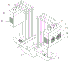
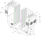
FIG. 1 is a perspective view of the present invention;
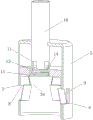
FIG. 2 is a schematic view of the structure of the pipe cap of the present invention;
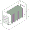
FIG. 3 is a schematic view of the structure of the cooling tank of the present invention;
FIG. 4 is an enlarged view of a portion of FIG. 3 at A;
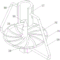
FIG. 5 is a schematic view of the structure of the support frame according to the present invention;
FIG. 6 is a schematic view of the structure of the turntable in the present invention;
FIG. 7 is a schematic view of a stopper according to the present invention;
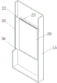
FIG. 8 is a schematic view of the structure of the handle of the present invention;
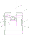
FIG. 9 is a state diagram showing the top pipe inserted into the inside of the plugging cap;
in the figure: 1. a case; 2. a liquid discharge hole; 3. a centrifugal pump; 4. a spray box; 5. a tube cap; 6. a vent; 7. a blocking cap; 8. an air inlet; 9. a closure plate; 10. jacking pipes; 11. an opening; 12. a countersunk hole; 13. blocking; 14. a spring; 15. a cooling box; 16. a filler; 17. a fan; 18. an air outlet; 19. a baffle; 20. a breathable film; 21. a connection frame; 22. a mounting groove; 23. a mounting frame; 24. a magnet frame I; 25. a seal ring; 26. a magnet frame II; 27. a conduit; 28. a support frame; 29. a motor; 30. a thermoelectric generation chip; 31. a turntable; 32. an arc-shaped groove; 33. a push rod; 34. a conical protrusion; 35. a limiting plate; 36. a limiting block; 37. a handle; 38. and the elastic sheet.
Detailed Description
The invention is further described in connection with the following detailed description in order to make the technical means, the creation characteristics, the achievement of the purpose and the effect of the invention easy to understand.
Embodiment one: as shown in fig. 1, the alloy casting cooling device according to the embodiment of the invention comprises a box body 1, a liquid discharge hole 2, a centrifugal pump 3 and a spray box 4; two side walls of the box body 1 are provided with a plurality of liquid discharge holes 2 which are uniformly arranged at positions close to the top; centrifugal pumps 3 are arranged on two sides of the box body 1, and the liquid discharge holes 2 are communicated with the centrifugal pumps 3 through pipelines; a spray box 4 is arranged at the top of the centrifugal pump 3, and the spray box 4 is communicated with the centrifugal pump 3 through a pipeline; a plurality of uniformly arranged spray assemblies are arranged on the bottom surface of the spray box 4; the bottom surface of the spray box 4 is provided with a cooling component, and the cooling component is covered outside the spray component; the bottom of the cooling component is arranged on the side wall of the spray box 4, and the position close to the bottom is communicated through a plurality of pipelines; when the alloy casting is in operation, after casting is completed, the alloy casting is required to be cooled, therefore, the embodiment of the invention can be used, firstly, a worker introduces cooling liquid into the box body 1, the cooling liquid is water, the liquid level of the cooling liquid is higher than that of the liquid discharge hole 2, then the centrifugal pump 3 is started, then the worker can submerge a workpiece in the cooling liquid, heat of the workpiece is transferred into the cooling liquid through heat conduction between the workpiece and the cooling liquid, the heated cooling liquid floats upwards due to density reduction and is pumped out of the liquid discharge hole 2 by the centrifugal pump 3, and then is pumped into the spray box 4, then the cooling liquid is sprayed into the cooling component through the spray component at the bottom of the spray box 4, the cooling component is used for cooling the cooling liquid, and the cooling component is communicated with the box body 1 through a pipeline, so that the cooling component and the box body 1 form a communicating device, and the cooled cooling liquid can flow back into the box body 1 through the pipeline again, and the cooling liquid in the box body 1 is enabled to be at a lower temperature through continuous circulation heat dissipation, so that the cooling liquid in the box body 1 is enabled to be in the state of the alloy casting, and the cooling effect of the cooling liquid is improved.
As shown in fig. 1, 2 and 9, the top surface of the spray box 4 is fixedly connected with a plurality of pipe caps 5 which are uniformly arranged, and the pipe caps 5 are communicated with the spray box 4; a plurality of uniformly arranged air vents 6 are formed in the side surface of the pipe cap 5; the inner wall of the pipe cap 5 is connected with a blocking cap 7 in a sliding manner; the side surface of the blocking cap 7 is provided with an air inlet 8 at the position corresponding to the air outlet; the side wall of the bottom of the air inlet 8 is rotationally connected with a blocking plate 9 in the blocking cap 7, and the blocking plate 9 is matched with the air inlet 8; a spring piece 38 is fixedly connected between the blocking plate 9 and the blocking cap 7; when the centrifugal pump 3 pumps the cooling liquid into the spray box 4, if the cooling liquid is not fully filled in the spray box 4, the elastic sheet 38 pushes the blocking plate 9 away from the air inlet 8, and meanwhile, because the air inlet 6 of the pipe cap 5 is overlapped with the air inlet 8 of the blocking cap 7, air can normally enter the spray assembly, and then the spray box 4 is communicated with the external atmosphere, so that the cooling liquid can be sprayed out of the spray assembly more easily, and if the spray box 4 is pumped with excessive cooling liquid, the cooling liquid can rush into the blocking cap 7 and push the blocking plate 9 to cover the air inlet 8, thereby closing the air inlet 8, preventing the scalding cooling liquid from flowing outwards and injuring staff.
As shown in fig. 2 and 9, the top of the pipe cap 5 is fixed with a jacking pipe 10, and the jacking pipe 10 extends to the inside of the pipe cap 5; a plurality of uniformly arranged openings 11 are formed in the side surface of the jacking pipe 10; the top surface of the plugging cap 7 is provided with a countersunk hole 12 at a position corresponding to the jacking pipe 10; the countersunk head hole 12 is connected with a blocking block 13 in a sliding way, and the blocking block 13 is arranged in a circular structure; a spring 14 is fixedly connected between the blocking block 13 and the inner wall of the counter bore 12; when the cooling liquid is fully filled in the spray box 4, if the centrifugal pump 3 is not closed in time by a user, the centrifugal pump 3 continuously pumps the cooling liquid into the spray box 4, the pumped cooling liquid can flow into the inner part of the blocking cap 7, after the blocking plate 9 is pushed to close the air inlet 8, the blocking cap 7 is continuously pushed to move towards the top pipe 10 along the inner wall of the pipe cap 5, when the top pipe 10 is pushed to the blocking block 13, the blocking block 13 can be pushed to the inner part of the blocking cap 7, and the spring 14 is stretched, finally the top pipe 10 is inserted into the blocking cap 7, so that the excessively pumped cooling liquid can flow back to the box 1 through the opening 11 on the surface of the top pipe 10, and the situation that the spray box 4 is filled with too much cooling liquid at high temperature to cause the explosion of the spray box 4 is avoided.
As shown in fig. 1 and 3, the cooling tank 15 is internally installed with a packing 16; the filler 16 is a cooling tower filler, and the main material is polypropylene; a plurality of uniformly arranged fans 17 are arranged on one side of the cooling box 15 far away from the box body 1; air outlets 18 are formed in two sides of the cooling box 15; when the cooling liquid is sprayed into the cooling box 15 during operation, the cooling liquid can be sprayed on the surface of the filler 16, meanwhile, the fan 17 is started, external air is blown into the cooling box 15, and then the air is discharged from the air outlets 18 on two sides of the cooling box 15, so that the cooling liquid is radiated through the air, and the contact surface between the cooling liquid and the air is further increased by the filler 16, so that the radiating efficiency and the radiating effect of the cooling liquid are further improved.
As shown in fig. 1 and 3, the side wall of the air outlet 18 is fixedly connected with a plurality of baffles 19 which are uniformly arranged; the inner wall of the cooling box 15 is provided with a ventilated membrane 20 at a position corresponding to the baffle 19; the gas permeable membrane 20 allows gas to pass therethrough, while liquid cannot pass therethrough; when the air conditioner works, when hot air blown out by the fan 17 is discharged through the air outlet 18, the discharged hot air can be blocked by the air permeable membrane 20, the air permeable membrane 20 can block partial condensed water vapor, and hot air is discharged through the air permeable membrane 20, so that water vapor loss is reduced, the purpose of saving water is achieved, meanwhile, the baffle 19 can also provide support for the air permeable membrane 20, and breakage of the air permeable membrane 20 due to aging caused by long-time blowing of the air permeable membrane 20 is reduced.
As shown in fig. 3, a connection frame 21 is fixedly connected around the air outlet 18 on the inner wall of the cooling box 15; the cooling box 15 is close to one side surface of the fan 17, and a mounting groove 22 is formed at a position corresponding to the connecting frame 21; the periphery of the breathable film 20 is fixedly connected with a mounting frame 23 matched with the connecting frame 21, and the mounting frame 23 is in sliding connection with the mounting groove 22; when the ventilating film 20 is required to be replaced, a worker only needs to draw the mounting frame 23 out of the mounting groove 22, then inserts the new ventilating film 20 required to be replaced into the mounting groove 22 together with the mounting frame 23, and when the fan 17 starts to work, the discharged gas tightly presses the mounting frame 23 on the surface of the connecting frame 21, so that gaps between the connecting frame 21 and the mounting frame 23 are reduced, and water vapor loss is reduced.
As shown in fig. 3 to 4, a first magnet frame 24 is fixedly connected to a surface of the connecting frame 21, which is close to the mounting frame 23; a sealing ring 25 is fixedly connected to one side of the mounting frame 23, which is close to the magnet frame; a magnet frame II 26 is embedded in the sealing ring 25; the first magnet frame 24 and the second magnet frame 26 are attracted to each other; when the connecting frame 21 and the mounting frame 23 are mutually attached, the first magnet frame 24 on the surface of the connecting frame 21 and the second magnet block inside the sealing ring 25 are mutually attracted, so that the sealing ring 25 can be tightly attached to the connecting frame 21, gaps between the mounting frame 23 and the connecting frame 21 are made up through deformation of the sealing ring 25, sealing performance between the mounting frame 23 and the connecting frame 21 is further improved, and water vapor waste is further reduced.
As shown in fig. 1, 5 and 6, the conduit 27 communicates with the shower box 4; the bottom of the conduit 27 is fixedly connected with a supporting frame 28; the bottom of the supporting frame 28 is fixedly connected with a motor 29; the outer side wall of the conduit 27 is fixedly connected with a thermoelectric generation chip 30, and the thermoelectric generation chip 30 is connected with a motor 29 through a wire; the output end of the motor 29 is fixedly connected with a rotary table 31; the top surface of the turntable 31 is provided with a plurality of arc-shaped grooves 32 which are uniformly arranged; the connection relation of the motor 29 is that the prior art does not need redundant description, and the specific model is selected according to the need; when the cooling liquid in the spray box 4 flows to the spray assembly in operation, the cooling liquid can firstly flow into the guide pipe 27, and the cooling liquid in the guide pipe 27 is not radiated, so that the temperature difference exists between the surface of the guide pipe 27 and the inside of the cooling box 15, the thermoelectric generation chip 30 generates electric power, the electric power is transmitted to the motor 29, the motor 29 is driven to drive the turntable 31 to rotate, when the cooling liquid flows out of the guide pipe 27 and falls on the top surface of the turntable 31, the arc-shaped groove 32 on the surface of the turntable 31 can drive the cooling liquid to rotate together, and the cooling liquid is thrown away from the turntable 31 through the centrifugal effect, so that the contact area of the cooling liquid and air is enlarged, and the cooling effect of the fan 17 on the cooling liquid is improved.
As shown in fig. 5 to 6, a push rod 33 is fixedly connected to the center of the top surface of the turntable 31; the top surface of the ejector rod 33 is fixedly connected with a conical protrusion 34; the columnar bulge is made of rigid materials; when the rotary table 31 rotates, the rotary table 31 drives the ejector rod 33 on the top surface of the rotary table to rotate, the ejector rod 33 drives the conical protrusion 34 to rotate, and the top of the conical protrusion 34 is positioned inside the guide pipe 27, so that the cooling liquid can be drained, and meanwhile, the tension of the cooling liquid at the end surface of the guide pipe 27 can be destroyed, so that the cooling liquid in the guide pipe 27 can flow down more smoothly.
Embodiment two: as shown in fig. 7 to 8, a comparative example one in which another embodiment of the present invention is: the surface of one side of the mounting frame 23, which is close to the fan 17, is fixedly connected with a limiting plate 35; a limiting block 36 is fixedly connected to a surface of one side, far away from the fan 17, of the inner wall of the mounting groove 22; the limiting block 36 is matched with the mounting frame 23; a handle 37 is fixedly connected to one side, away from the mounting frame 23, of the limiting plate 35; during operation, when the breathable film 20 needs to be replaced, a user can draw out the mounting frame 23 and the breathable film 20 from the mounting groove 22 through the handle 37, and meanwhile, when the mounting frame 23 and the breathable film 20 are plugged back into the mounting groove 22, the limiting block 36 can also play a role in blocking and limiting the limiting plate 35, so that the mounting frame 23 can be exactly aligned with the connecting frame 21, gaps between the mounting frame 23 and the connecting frame 21 caused by dislocation are avoided, water vapor escape is caused, and further water resource waste is caused.
When the alloy casting is in operation, the alloy casting is required to be cooled after casting, so that the embodiment of the invention can be used, firstly, a worker introduces cooling liquid into the box body 1, the liquid level of the cooling liquid is higher than that of the liquid discharge hole 2, then the centrifugal pump 3 is started, then the worker can submerge a workpiece in the cooling liquid, heat of the workpiece is transferred into the cooling liquid through heat conduction between the workpiece and the cooling liquid, the heated cooling liquid floats upwards due to density reduction and is pumped out from the liquid discharge hole 2 by the centrifugal pump 3, then the heated cooling liquid is pumped into the spray box 4, then the cooling liquid is sprayed into the cooling component through the spray component at the bottom of the spray box 4, the cooling component is cooled by the cooling component, and the cooling component is communicated with the box body 1 through a pipeline, so that the cooling component and the box body 1 form a communicating vessel, and the cooled cooling liquid can flow back into the box body 1 through the pipeline, and the cooling liquid in the box body 1 is enabled to be at a lower temperature through continuous circulation heat dissipation, so that the cooling liquid in the box body 1 is enabled to be in a lower temperature, and the cooling effect of the alloy casting is improved.
When the centrifugal pump 3 pumps the cooling liquid into the spray box 4, if the cooling liquid is not fully filled in the spray box 4, the elastic sheet 38 pushes the blocking plate 9 away from the air inlet 8, and meanwhile, because the air inlet 6 of the pipe cap 5 is overlapped with the air inlet 8 of the blocking cap 7, air can normally enter the spray assembly, and then the spray box 4 is communicated with the external atmosphere, so that the cooling liquid can be sprayed out of the spray assembly more easily, and if too much cooling liquid is pumped in the spray box 4, the cooling liquid can rush into the blocking cap 7 and push the blocking plate 9 to cover the air inlet 8, thereby closing the air inlet 8, preventing the scalding cooling liquid from flowing outwards and causing injury to working personnel.
When the spray tank 4 is full of cooling liquid, if the centrifugal pump 3 is not closed in time by a user, the centrifugal pump 3 continues to pump cooling liquid into the spray tank 4, the pumped cooling liquid can flow into the interior of the blocking cap 7, after the blocking plate 9 is pushed to close the air inlet 8, the blocking cap 7 is pushed to move towards the top pipe 10 along the inner wall of the pipe cap 5, when the top pipe 10 is pushed to the blocking block 13, the blocking block 13 can be pushed into the interior of the blocking cap 7, and the spring 14 is stretched, finally the top pipe 10 is inserted into the blocking cap 7, so that the excessively pumped cooling liquid flows back to the tank 1 through the opening 11 on the surface of the top pipe 10, and the situation that the spray tank 4 is filled with too much cooling liquid at high temperature to cause explosion of the spray tank 4 is avoided.
When the cooling liquid is sprayed into the cooling box 15, the cooling liquid can be sprayed on the surface of the filler 16, meanwhile, the fan 17 is started, external air is blown into the cooling box 15, and then the air is discharged from the air outlets 18 on two sides of the cooling box 15, so that the cooling liquid is radiated through the air, and the contact surface of the cooling liquid and the air is further increased by the filler 16, so that the radiating efficiency and the radiating effect of the cooling liquid are further improved.
When the hot air blown out by the fan 17 is discharged through the air outlet 18, the discharged hot air can be blocked by the air permeable membrane 20, the air permeable membrane 20 can block partial condensed water vapor, and hot air is discharged through the air permeable membrane 20, so that the water vapor loss is reduced, the purpose of saving water is achieved, meanwhile, the baffle 19 can also provide support for the air permeable membrane 20, and the breakage of the air permeable membrane 20 caused by aging due to long-time blowing of the air permeable membrane 20 is reduced.
When the ventilation film 20 needs to be replaced, a worker only needs to draw the mounting frame 23 out of the mounting groove 22, then inserts a new ventilation film 20 which needs to be replaced into the mounting groove 22 together with the mounting frame 23, and when the fan 17 starts to work, the discharged air tightly presses the mounting frame 23 on the surface of the connecting frame 21, so that gaps between the connecting frame 21 and the mounting frame 23 are reduced, and water vapor loss is reduced.
When the connecting frame 21 is mutually attached to the mounting frame 23, the first magnet frame 24 on the surface of the connecting frame 21 and the second magnet block inside the sealing ring 25 are mutually attracted, so that the sealing ring 25 can be tightly attached to the connecting frame 21, gaps between the mounting frame 23 and the connecting frame 21 are made up through deformation of the sealing ring 25, sealing performance between the mounting frame 23 and the connecting frame 21 is further improved, and water vapor waste is further reduced.
When the cooling liquid in the spray box 4 flows to the spray assembly, the cooling liquid can flow into the guide pipe 27 firstly, and the cooling liquid in the guide pipe 27 is not radiated, so that the temperature difference exists between the surface of the guide pipe 27 and the inside of the cooling box 15, the thermoelectric generation chip 30 generates electric power, the electric power is transmitted to the motor 29, the motor 29 is driven to drive the turntable 31 to rotate, when the cooling liquid flows out of the guide pipe 27 and falls on the top surface of the turntable 31, the arc-shaped groove 32 on the surface of the turntable 31 can drive the cooling liquid to rotate together, and the cooling liquid is thrown away from the turntable 31 through the centrifugal effect, so that the contact area of the cooling liquid and air is enlarged, and the cooling effect of the fan 17 on the cooling liquid is improved.
When the turntable 31 rotates, the turntable 31 drives the ejector rod 33 on the top surface to rotate, the ejector rod 33 drives the conical protrusion 34 to rotate, and the top of the conical protrusion 34 is positioned inside the guide pipe 27, so that the cooling liquid can be drained, and meanwhile, the tension of the cooling liquid at the end surface of the guide pipe 27 can be destroyed, so that the cooling liquid in the guide pipe 27 can flow down more smoothly.
When the breathable film 20 is required to be replaced, a user can draw out the mounting frame 23 and the breathable film 20 from the mounting groove 22 through the handle 37, and meanwhile, when the mounting frame 23 and the breathable film 20 are inserted back into the mounting groove 22, the limiting block 36 can also block and limit the limiting plate 35, so that the mounting frame 23 can be exactly aligned with the connecting frame 21, gaps between the mounting frame 23 and the connecting frame 21 caused by dislocation are avoided, water vapor is caused to escape, and water resources are wasted.
The foregoing has shown and described the basic principles, principal features and advantages of the invention. It will be understood by those skilled in the art that the present invention is not limited to the embodiments described above, and that the above embodiments and descriptions are merely illustrative of the principles of the present invention, and various changes and modifications may be made without departing from the spirit and scope of the invention, which is defined in the appended claims. The scope of the invention is defined by the appended claims and equivalents thereof.
Claims (10)
1. An alloy casting cooling device is characterized in that: comprises a box body (1); two side walls of the box body (1) are provided with a plurality of liquid discharge holes (2) which are uniformly arranged at positions close to the top; centrifugal pumps (3) are arranged on two sides of the box body (1), and the liquid discharge holes (2) are communicated with the centrifugal pumps (3) through pipelines; the top of the centrifugal pump (3) is provided with a spray box (4), and the spray box (4) is communicated with the centrifugal pump (3) through a pipeline; a plurality of uniformly arranged spray assemblies are arranged on the bottom surface of the spray box (4); the bottom surface of the spray box (4) is provided with a cooling component, and the cooling component is covered outside the spray component; the bottom of the cooling component is arranged on the side wall of the spray box (4), and the position close to the bottom is communicated through a plurality of pipelines.
2. An alloy casting cooling apparatus as claimed in claim 1, wherein: the top surface of the spray box (4) is fixedly connected with a plurality of pipe caps (5) which are uniformly arranged, and the pipe caps (5) are communicated with the spray box (4); a plurality of uniformly arranged air vents (6) are formed in the side surface of the pipe cap (5); the inner wall of the pipe cap (5) is connected with a blocking cap (7) in a sliding manner; an air inlet (8) is formed in the side surface of the blocking cap (7) at the position corresponding to the air outlet hole; the side wall of the bottom of the air inlet (8) is rotationally connected with a blocking plate (9) at the blocking cap (7); an elastic sheet (38) is fixedly connected between the blocking plate (9) and the blocking cap (7).
3. An alloy casting cooling apparatus as claimed in claim 2, wherein: a jacking pipe (10) is fixed at the top of the pipe cap (5), and the jacking pipe (10) extends to the inside of the pipe cap (5); a plurality of uniformly arranged openings (11) are formed in the side surface of the jacking pipe (10); the top surface of the plugging cap (7) is provided with a countersunk hole (12) at a position corresponding to the jacking pipe (10); a blocking block (13) is connected in the counter bore (12) in a sliding way; a spring (14) is fixedly connected between the blocking block (13) and the inner wall of the counter bore (12).
4. An alloy casting cooling apparatus as claimed in claim 1, wherein: the cooling assembly comprises a cooling tank (15); a filler (16) is arranged in the cooling box (15); a plurality of uniformly arranged fans (17) are arranged on one side, far away from the box body (1), of the cooling box (15); air outlets (18) are formed in two sides of the cooling box (15).
5. An alloy casting cooling apparatus as claimed in claim 4, wherein: the side wall of the air outlet (18) is fixedly connected with a plurality of baffle plates (19) which are uniformly arranged; and a ventilated membrane (20) is arranged at the position of the inner wall of the cooling box (15) corresponding to the baffle plate (19).
6. An alloy casting cooling apparatus as claimed in claim 5, wherein: the inner wall of the cooling box (15) is fixedly connected with a connecting frame (21) around the air outlet (18); the cooling box (15) is close to one side surface of the fan (17), and a mounting groove (22) is formed in a position corresponding to the connecting frame (21); the periphery of the breathable film (20) is fixedly connected with a mounting frame (23) which is matched with the connecting frame (21), and the mounting frame (23) is in sliding connection with the mounting groove (22).
7. An alloy casting cooling apparatus as claimed in claim 6, wherein: a first magnet frame (24) is fixedly connected to the surface of one side, close to the mounting frame (23), of the connecting frame (21); a sealing ring (25) is fixedly connected to one side, close to the magnet frame, of the mounting frame (23); and a magnet frame II (26) is embedded in the sealing ring (25).
8. An alloy casting cooling apparatus as claimed in claim 1, wherein: the spray assembly comprises a conduit (27); the conduit (27) is communicated with the spray box (4); the bottom of the conduit (27) is fixedly connected with a supporting frame (28); the bottom of the supporting frame (28) is fixedly connected with a motor (29); the outer side wall of the conduit (27) is fixedly connected with a thermoelectric generation chip (30), and the thermoelectric generation chip (30) is connected with a motor (29) through a wire; the output end of the motor (29) is fixedly connected with a rotary table (31); a plurality of arc-shaped grooves (32) which are uniformly arranged are formed in the top surface of the rotary disc (31).
9. An alloy casting cooling apparatus as claimed in claim 8, wherein: a push rod (33) is fixedly connected to the center of the top surface of the turntable (31); the top surface of the ejector rod (33) is fixedly connected with a conical bulge (34).
10. An alloy casting cooling apparatus as claimed in claim 5, wherein: a limiting plate (35) is fixedly connected to the surface of one side, close to the fan (17), of the mounting frame (23); a limiting block (36) is fixedly connected to a surface of one side, far away from the fan (17), of the inner wall of the mounting groove (22); one side of the limiting plate (35) far away from the mounting frame (23) is fixedly connected with a handle (37).
Priority Applications (1)
| Application Number | Priority Date | Filing Date | Title |
|---|---|---|---|
| CN202310565749.XA CN116274968B (en) | 2023-05-19 | 2023-05-19 | Alloy casting cooling device |
Applications Claiming Priority (1)
| Application Number | Priority Date | Filing Date | Title |
|---|---|---|---|
| CN202310565749.XA CN116274968B (en) | 2023-05-19 | 2023-05-19 | Alloy casting cooling device |
Publications (2)
| Publication Number | Publication Date |
|---|---|
| CN116274968A true CN116274968A (en) | 2023-06-23 |
| CN116274968B CN116274968B (en) | 2023-08-04 |
Family
ID=86815278
Family Applications (1)
| Application Number | Title | Priority Date | Filing Date |
|---|---|---|---|
| CN202310565749.XA Active CN116274968B (en) | 2023-05-19 | 2023-05-19 | Alloy casting cooling device |
Country Status (1)
| Country | Link |
|---|---|
| CN (1) | CN116274968B (en) |
Citations (11)
| Publication number | Priority date | Publication date | Assignee | Title |
|---|---|---|---|---|
| CN101140118A (en) * | 2007-10-16 | 2008-03-12 | 华南理工大学 | Aluminum harmonica plate plate evaporative condenser |
| CN209468477U (en) * | 2019-01-27 | 2019-10-08 | 韶关市曲江韶枫实业有限公司 | A kind of auxiliary apparatus for cooling of iron casting |
| CN111006534A (en) * | 2019-12-13 | 2020-04-14 | 瀚润联合高科技发展(北京)有限公司 | A tube immersion cooling system |
| CN211028062U (en) * | 2019-07-03 | 2020-07-17 | 扬州贤义达机械铸件有限公司 | Quick cooling water tank for iron casting processing |
| CN213388793U (en) * | 2020-09-22 | 2021-06-08 | 江苏诺丰科技有限公司 | Water spray shower quenching device for metallurgical casting |
| CN214023455U (en) * | 2020-12-07 | 2021-08-24 | 力嘉集团有限公司 | Cooling device is used in processing of foundry goods product |
| CN214977635U (en) * | 2021-01-22 | 2021-12-03 | 焦作汉为精密机械科技有限公司 | Magnesium alloy precision casting cooling arrangement |
| CN216801642U (en) * | 2021-10-08 | 2022-06-24 | 繁昌县金科机电科技股份有限公司 | Valve casting cooling device |
| CN217044560U (en) * | 2021-12-10 | 2022-07-26 | 江苏弘烨精密铸造有限公司 | Cooling device for casting production |
| CN218361989U (en) * | 2022-08-17 | 2023-01-24 | 南阳超联铸造有限公司 | Mould cooling device for casting |
| CN115790202A (en) * | 2022-11-28 | 2023-03-14 | 方诺传热系统(江苏)有限公司 | Composite flow closed cooling tower capable of being used for water-saving reconstruction |
-
2023
- 2023-05-19 CN CN202310565749.XA patent/CN116274968B/en active Active
Patent Citations (11)
| Publication number | Priority date | Publication date | Assignee | Title |
|---|---|---|---|---|
| CN101140118A (en) * | 2007-10-16 | 2008-03-12 | 华南理工大学 | Aluminum harmonica plate plate evaporative condenser |
| CN209468477U (en) * | 2019-01-27 | 2019-10-08 | 韶关市曲江韶枫实业有限公司 | A kind of auxiliary apparatus for cooling of iron casting |
| CN211028062U (en) * | 2019-07-03 | 2020-07-17 | 扬州贤义达机械铸件有限公司 | Quick cooling water tank for iron casting processing |
| CN111006534A (en) * | 2019-12-13 | 2020-04-14 | 瀚润联合高科技发展(北京)有限公司 | A tube immersion cooling system |
| CN213388793U (en) * | 2020-09-22 | 2021-06-08 | 江苏诺丰科技有限公司 | Water spray shower quenching device for metallurgical casting |
| CN214023455U (en) * | 2020-12-07 | 2021-08-24 | 力嘉集团有限公司 | Cooling device is used in processing of foundry goods product |
| CN214977635U (en) * | 2021-01-22 | 2021-12-03 | 焦作汉为精密机械科技有限公司 | Magnesium alloy precision casting cooling arrangement |
| CN216801642U (en) * | 2021-10-08 | 2022-06-24 | 繁昌县金科机电科技股份有限公司 | Valve casting cooling device |
| CN217044560U (en) * | 2021-12-10 | 2022-07-26 | 江苏弘烨精密铸造有限公司 | Cooling device for casting production |
| CN218361989U (en) * | 2022-08-17 | 2023-01-24 | 南阳超联铸造有限公司 | Mould cooling device for casting |
| CN115790202A (en) * | 2022-11-28 | 2023-03-14 | 方诺传热系统(江苏)有限公司 | Composite flow closed cooling tower capable of being used for water-saving reconstruction |
Also Published As
| Publication number | Publication date |
|---|---|
| CN116274968B (en) | 2023-08-04 |
Similar Documents
| Publication | Publication Date | Title |
|---|---|---|
| CN106655596A (en) | Internal-external dual-circulating type self-ventilation cooling structure of totally-enclosed motor | |
| CN212323098U (en) | New energy automobile battery package constant temperature equipment | |
| CN206096736U (en) | Heat exchanger, colour wheel heat dissipation module and projection arrangement | |
| CN208691072U (en) | A kind of cooling end cap of labyrinth type | |
| CN116274968B (en) | Alloy casting cooling device | |
| CN106200845A (en) | A kind of desktop cpu chiller | |
| CN221285455U (en) | Cooling system and cooking appliance with same | |
| CN220973944U (en) | Fill electric pile heat abstractor | |
| CN108612837B (en) | Transmission case shell | |
| CN217481575U (en) | Centrifugal fan for high-temperature environment | |
| CN208187156U (en) | A kind of flooded type cooling tower | |
| CN218646017U (en) | Sintering furnace | |
| CN216016539U (en) | Distribution network safety monitoring device based on 5G communication technology | |
| CN114744815B (en) | Heat dissipation variable frequency speed regulating motor | |
| CN205878924U (en) | Quick cooling system of high temperature furnace | |
| CN213590808U (en) | Gas-liquid combined temperature control device | |
| CN2876665Y (en) | Heat exchange type high-pressure fan gas circulation cooler for vacuum electric stove | |
| CN218514756U (en) | Low-voltage complete energy-saving control cabinet | |
| CN219551265U (en) | Low-temperature methanol washing heat exchange system | |
| CN218033938U (en) | Welding equipment cooling water circulation system | |
| CN217636870U (en) | Small-capacity cooling tower for high-temperature waste gas | |
| CN215295428U (en) | Constant-temperature uniform-wind-speed cooling device | |
| CN218920181U (en) | Miniature motor with strong heat dissipation performance | |
| CN205503517U (en) | From cooling blower | |
| CN223345771U (en) | Cooling device of micro push rod solidifying equipment |
Legal Events
| Date | Code | Title | Description |
|---|---|---|---|
| PB01 | Publication | ||
| PB01 | Publication | ||
| SE01 | Entry into force of request for substantive examination | ||
| SE01 | Entry into force of request for substantive examination | ||
| GR01 | Patent grant | ||
| GR01 | Patent grant |