CN116274532A - Full-automatic pipe bending machine - Google Patents
Full-automatic pipe bending machine Download PDFInfo
- Publication number
- CN116274532A CN116274532A CN202310383611.8A CN202310383611A CN116274532A CN 116274532 A CN116274532 A CN 116274532A CN 202310383611 A CN202310383611 A CN 202310383611A CN 116274532 A CN116274532 A CN 116274532A
- Authority
- CN
- China
- Prior art keywords
- fixedly connected
- top surface
- plate
- sliding
- frame
- Prior art date
- Legal status (The legal status is an assumption and is not a legal conclusion. Google has not performed a legal analysis and makes no representation as to the accuracy of the status listed.)
- Withdrawn
Links
- 238000005452 bending Methods 0.000 title claims abstract description 61
- 238000006073 displacement reaction Methods 0.000 claims abstract description 16
- 230000008878 coupling Effects 0.000 claims description 41
- 238000010168 coupling process Methods 0.000 claims description 41
- 238000005859 coupling reaction Methods 0.000 claims description 41
- 230000007246 mechanism Effects 0.000 claims description 18
- 230000005540 biological transmission Effects 0.000 claims description 7
- 230000001105 regulatory effect Effects 0.000 claims description 6
- 244000309464 bull Species 0.000 claims description 4
- 230000000694 effects Effects 0.000 abstract description 5
- 230000006978 adaptation Effects 0.000 abstract description 3
- 230000009471 action Effects 0.000 description 4
- 238000010586 diagram Methods 0.000 description 4
- 238000003780 insertion Methods 0.000 description 4
- 230000037431 insertion Effects 0.000 description 4
- 230000002159 abnormal effect Effects 0.000 description 3
- 230000004075 alteration Effects 0.000 description 1
- 230000009286 beneficial effect Effects 0.000 description 1
- 230000007547 defect Effects 0.000 description 1
- 238000004880 explosion Methods 0.000 description 1
- 239000000463 material Substances 0.000 description 1
- 238000000034 method Methods 0.000 description 1
- 230000005012 migration Effects 0.000 description 1
- 238000013508 migration Methods 0.000 description 1
- 238000012986 modification Methods 0.000 description 1
- 230000004048 modification Effects 0.000 description 1
- 230000008569 process Effects 0.000 description 1
- 238000000926 separation method Methods 0.000 description 1
- 238000006467 substitution reaction Methods 0.000 description 1
Images
Classifications
-
- B—PERFORMING OPERATIONS; TRANSPORTING
- B21—MECHANICAL METAL-WORKING WITHOUT ESSENTIALLY REMOVING MATERIAL; PUNCHING METAL
- B21D—WORKING OR PROCESSING OF SHEET METAL OR METAL TUBES, RODS OR PROFILES WITHOUT ESSENTIALLY REMOVING MATERIAL; PUNCHING METAL
- B21D7/00—Bending rods, profiles, or tubes
- B21D7/02—Bending rods, profiles, or tubes over a stationary forming member; by use of a swinging forming member or abutment
- B21D7/024—Bending rods, profiles, or tubes over a stationary forming member; by use of a swinging forming member or abutment by a swinging forming member
-
- B—PERFORMING OPERATIONS; TRANSPORTING
- B21—MECHANICAL METAL-WORKING WITHOUT ESSENTIALLY REMOVING MATERIAL; PUNCHING METAL
- B21D—WORKING OR PROCESSING OF SHEET METAL OR METAL TUBES, RODS OR PROFILES WITHOUT ESSENTIALLY REMOVING MATERIAL; PUNCHING METAL
- B21D37/00—Tools as parts of machines covered by this subclass
- B21D37/04—Movable or exchangeable mountings for tools
-
- B—PERFORMING OPERATIONS; TRANSPORTING
- B21—MECHANICAL METAL-WORKING WITHOUT ESSENTIALLY REMOVING MATERIAL; PUNCHING METAL
- B21D—WORKING OR PROCESSING OF SHEET METAL OR METAL TUBES, RODS OR PROFILES WITHOUT ESSENTIALLY REMOVING MATERIAL; PUNCHING METAL
- B21D43/00—Feeding, positioning or storing devices combined with, or arranged in, or specially adapted for use in connection with, apparatus for working or processing sheet metal, metal tubes or metal profiles; Associations therewith of cutting devices
- B21D43/003—Positioning devices
-
- Y—GENERAL TAGGING OF NEW TECHNOLOGICAL DEVELOPMENTS; GENERAL TAGGING OF CROSS-SECTIONAL TECHNOLOGIES SPANNING OVER SEVERAL SECTIONS OF THE IPC; TECHNICAL SUBJECTS COVERED BY FORMER USPC CROSS-REFERENCE ART COLLECTIONS [XRACs] AND DIGESTS
- Y02—TECHNOLOGIES OR APPLICATIONS FOR MITIGATION OR ADAPTATION AGAINST CLIMATE CHANGE
- Y02P—CLIMATE CHANGE MITIGATION TECHNOLOGIES IN THE PRODUCTION OR PROCESSING OF GOODS
- Y02P40/00—Technologies relating to the processing of minerals
- Y02P40/50—Glass production, e.g. reusing waste heat during processing or shaping
- Y02P40/57—Improving the yield, e-g- reduction of reject rates
Landscapes
- Engineering & Computer Science (AREA)
- Mechanical Engineering (AREA)
- Bending Of Plates, Rods, And Pipes (AREA)
Abstract
The invention discloses a full-automatic pipe bending machine which comprises a main frame, wherein the top surface of the main frame is fixedly connected with two main sliding rails, the two main sliding rails are horizontally and slidably connected with a feeding component, the top surface of one side of the main frame is vertically and fixedly connected with a support plate, an air cylinder is fixedly connected on the support plate, one end of the air cylinder, which is close to the feeding component, is fixedly connected with a core rod sleeve, and one side, which is far away from the support plate, of the main frame is fixedly connected with a displacement structure. The bent pipe grooved wheels are arranged on the bent pipe assembly, the clamping assembly is provided with the clamping groove plates, the jacking groove plates are arranged on the jacking assembly, and the bent pipe grooved wheels, the clamping groove plates and the jacking groove plates at different height positions can be adjusted to the positions of the pipes by matching with the lifting effect of the displacement structure, so that the bent pipe requirements on the pipes with various diameters can be met, the operation requirements on rounding corners at different bent pipe positions can also be met, the adaptation force can be improved during single-batch operation, and the situation that the bent pipe grooved wheels and the corresponding groove plates need to be replaced frequently during single-batch operation is avoided.
Description
Technical Field
The invention relates to the technical field of numerical control pipe bending machines, in particular to a full-automatic pipe bending machine.
Background
The pipe is a material for making a pipe fitting, bending treatment is needed in the use process of the pipe, the pipe is bent to have a bending amplitude suitable for use, a numerical control pipe bender is needed in bending the pipe, the numerical control pipe bender is far away from the pipe, a disc-shaped grooved pulley is matched with an auxiliary clamping structure to bend the pipe, a chamfering effect can occur on a bending part, the pipe bending stress is uniform, and the pipe cannot be broken, for example, the Chinese patent with the authority bulletin number of CN115488194A discloses a numerical control pipe bender, the numerical control pipe bender comprises an operation table, the top of the operation table is provided with a linear driving component, the top of the operation table is fixedly provided with a fixing plate through the linear driving component, the surface of the fixing plate is provided with a pipe clamping component, the left side of the operation table is fixedly provided with a supporting plate, the top of the supporting plate is fixedly provided with a clamping plate through the driving component, and the surface of the supporting plate is provided with a pipe bending component; however, the existing numerical control pipe bending machine has the following defects:
the pipe bending groove disc in the numerical control pipe bending machine is an important structure of a pipe bending, the diameter of the pipe bending groove disc determines the rounding radius of a bending part during pipe bending, the size of a groove in the pipe bending groove disc determines the diameter of a suitable pipe, the pipe with different sizes and the pipe bending operation requirement on the rounding radius of the pipe bending part are frequently met in single-batch pipe bending operation at present, and the pipe bending groove disc can be only assembled in the pipe bending machine at present, and the pipe bending groove disc can be disassembled and assembled for replacement, but the pipe bending groove disc and the corresponding clamping groove plate can be frequently replaced in single-batch operation, so that the operation efficiency is greatly influenced, and the use is not facilitated.
Therefore, we propose a fully automatic pipe bender to solve the above problems.
Disclosure of Invention
The invention aims to provide a full-automatic pipe bending machine so as to solve the problems in the prior art.
In order to achieve the above purpose, the present invention provides the following technical solutions: the utility model provides a full-automatic pipe bending machine, includes the main frame, two main slide rails are connected to main frame top surface rigid coupling, two horizontal sliding connection pay-off parts on the main slide rail, main frame one side top surface vertical fixation extension board, rigid coupling cylinder on the extension board, cylinder is close to pay-off parts one end rigid coupling core bar cover, main frame is kept away from extension board one side rigid coupling displacement structure, displacement structure is located main frame outside position rigid coupling return bend mechanism, return bend mechanism includes wheel mould part, press from both sides mould part and top tight mould part, wheel mould part includes first frame, first frame top surface rotates the connection revolving stage, the revolving stage top surface is provided with the return bend subassembly, press from both sides the mould part and include the diaphragm, diaphragm tip rigid coupling is at first frame top surface, diaphragm top surface swing joint slip table, slip table top surface horizontal sliding connection riser, riser is close to wheel mould part one side rigid coupling clamping assembly, top tight mould part includes the third frame, third frame top surface lateral wall rigid coupling is in the revolving stage outside, the movable table is connected to the movable table top surface, top surface sliding connection top surface subassembly is tight;
the bent pipe assembly comprises a seat table and a plurality of bent pipe grooved wheels, wherein the seat table is fixedly connected to the top surface of a turntable, a special-shaped shaft is vertically fixedly connected to the center of the top surface of the seat table, special-shaped holes are vertically formed in the center of the inner side of the bent pipe grooved wheels, a plurality of special-shaped holes on the bent pipe grooved wheels are sleeved on the outer side of the special-shaped shaft, a top cover plate is sleeved on the top end of the special-shaped shaft, a plurality of vertical rods are uniformly and vertically fixedly connected to the positions of the top surface of the seat table, a plurality of first insertion holes are formed in the bent pipe grooved wheels, a plurality of second insertion holes are formed in the top cover plate, corresponding to the same vertical positions of the vertical rods, the vertical rods penetrate through the first insertion holes and the second insertion holes and are fixedly connected with threaded columns, screw threads are sleeved with nuts, and one side of the bent pipe grooved wheels is fixedly connected with a wheel mold grooved plate;
the clamping assembly comprises a side plate and a plurality of clamping groove plates, wherein a plurality of positioning notches are uniformly formed in one side of the side plate, close to the turntable, of the side plate, a T-shaped groove is formed in the side wall of each positioning notch, a T-shaped strip is fixedly connected to the side wall of each clamping groove plate, each T-shaped strip is inserted into each T-shaped groove, a second square opening is vertically formed in each T-shaped strip, first square openings are formed in the side plate at the same vertical positions corresponding to the second square openings, mounting inserting plates are inserted into the first square openings and the second square openings, top strips are fixedly connected to the top surfaces of the mounting inserting plates, top openings are formed in the top ends of the first square openings, the top strips are inserted into the top openings, two sides of each top strip are vertically and rotatably connected with two mounting bolts, two first threaded holes are formed in the bottom surfaces of two ends of each top opening, and the mounting bolts are in threaded connection with the first threaded holes;
the tight subassembly in top includes plate body and a plurality of tight frid in top, plate body sliding connection is at the mobile station top surface, a plurality of installing ports are evenly seted up to plate body near revolving stage one side, tight frid in top is pegged graft in the installing port, a plurality of second through-holes are seted up perpendicularly in the tight frid in top, the plate body is located a plurality of second through-holes and sets up a plurality of first through-holes in same vertical position, a plurality of first through-hole and a plurality of second through-holes are pegged graft a plurality of inserted columns, a plurality of inserted column top surface rigid coupling cardboard, cardboard both sides contact plate body top surface both sides, two screw thread through-holes are seted up to cardboard both sides, two second screw holes are seted up to plate body top surface both sides, second screw hole and screw thread through-hole threaded connection side bolt.
Preferably, the displacement structure comprises a panel fixedly connected to the side wall of the main frame, two vertical guide rails are fixedly connected to one side of the panel away from the main frame, vertical sliding seats are vertically connected to the vertical guide rails in a sliding mode, adjusting plates are fixedly connected to the vertical sliding seats, two transverse guide rails are horizontally fixedly connected to one side of the adjusting plates away from the panel, transverse sliding seats are slidingly connected to the transverse guide rails, a main board body is fixedly connected to one side of the first frame, and the main board body is fixedly connected to the transverse sliding seats.
Preferably, the panel is located one side rigid coupling inner panel in the main frame, perpendicular logical groove is seted up perpendicularly on inner panel and the panel, perpendicular sliding connection lifter plate in the perpendicular logical groove, the lifter plate rigid coupling is on the regulating plate lateral wall, inner panel bottom surface rigid coupling second gear motor, second gear motor pivot end rigid coupling second lead screw, rigid coupling second screw thread sleeve in the lifter plate, second lead screw threaded connection second screw thread sleeve, horizontal logical groove is seted up to the regulating plate on the level, horizontal logical inslot level moves and connects the power board, the power board rigid coupling mainboard body, horizontal logical inslot outside level rotates and connects first lead screw, rigid coupling first screw thread sleeve on the power board, first lead screw threaded connection first screw thread sleeve, regulating plate one side rigid coupling first gear motor, first gear motor pivot end rigid coupling driven bevel gear, driven bevel gear is connected in the meshing of first lead screw.
Preferably, the notch is offered near return bend mechanism one side top surface to the main frame, horizontal motion connection rectification in the notch holds up the subassembly, rectification holds up the subassembly and includes the shell, two splint of horizontal rigid coupling respectively in the shell both sides, splint sliding sleeve joint is in notch edge, splint top surface threaded connection third locking bolt, third locking bolt contact main frame top surface.
Preferably, the top surface of the shell is horizontally provided with two top sliding ports, two sliding strips are horizontally and movably connected in the top sliding ports, the top surfaces of the sliding strips are respectively fixedly connected with two wheel seats, the two wheel seats are respectively and rotatably connected with two deviation correcting wheels on one sides close to each other, the two sliding strips are different in height, the bottom ends of the sliding strips are positioned in the shell and are respectively and horizontally fixedly connected with two toothed plates, a gear is rotatably connected between the two toothed plates in the shell, the two toothed plates are connected in a meshing manner, two return springs are respectively and fixedly connected between one sides of the sliding strips far away from each other and the end parts of the two top sliding ports, and the center position of the top surface of the shell is rotatably connected with the riding wheel.
Preferably, the bottom surface of the first frame is fixedly connected with a third gear motor, the rotating shaft end of the third gear motor is positioned in the first frame and fixedly connected with a driving sprocket, the rotating shaft end of the rotary table is positioned in the first frame and fixedly connected with a driven sprocket, and the outer sides of the driving sprocket and the driven sprocket are sleeved with a transmission chain.
Preferably, the bottom surface of the transverse plate is fixedly connected with the second frame, the bottom surface of the second frame is rotationally connected with the first hydraulic cylinder, the top end of the output end of the first hydraulic cylinder is fixedly connected with the special-shaped hinged support, the special-shaped hinged support is hinged with the rotary rod, the free end of the rotary rod is hinged with the second frame, the transverse plate is vertically provided with a through hole, the special-shaped hinged support is hinged with one end of the driven hinged support, the driven hinged support penetrates through the through hole and is fixedly connected with the bottom surface of the sliding table, the top surface of the sliding table is fixedly connected with a first socket, a first inserted rod is horizontally and movably sleeved in the first socket, the end part of the first inserted rod is fixedly connected with the side wall of the vertical plate, the top surface of the first socket is in threaded connection with a first locking bolt, and the first locking bolt is contacted with the surface of the first inserted rod.
Preferably, the third frame bottom surface rotates and connects the second pneumatic cylinder, second pneumatic cylinder output top rigid coupling power hinge, power hinge rotates and connects first connecting rod and second connecting rod one end, the first connecting rod other end rotates and connects mobile station bottom surface one end, the second connecting rod other end rotates and connects third connecting rod one end, the third connecting rod other end rotates and connects the mobile station bottom surface other end, mobile station top surface rigid coupling second socket, second socket horizontal slip cup joints the second inserted bar, second inserted bar tip fixed plate body lateral wall, second socket top surface threaded connection second locking bolt, second locking bolt bottom contact second inserted bar surface.
Preferably, the feeding component comprises a sliding plate seat, two main sliding rails are connected in a sliding manner, the top surface of the sliding plate seat is fixedly connected with a shell, the shell is rotationally connected with a feeding sleeve shaft, a taper sleeve is sleeved outside one end of the feeding sleeve shaft close to the pipe bending mechanism, the circumference of the end part of the feeding sleeve shaft is slidingly connected with a plurality of clamping jaws, the end part of the taper sleeve is contacted with the outer side of the clamping jaws, the top surface of the shell is fixedly connected with an upper hinged support, the upper hinged support is rotationally connected with a third hydraulic cylinder, an output shaft of the third hydraulic cylinder is fixedly connected with a supporting rod, the supporting rod is rotationally connected with a shifting fork, and the shifting fork is rotationally connected outside the taper sleeve.
Preferably, one side of the casing is fixedly connected with a fourth gear motor, an output shaft of the fourth gear motor is positioned in the casing and fixedly connected with a driving belt wheel, the feeding sleeve shaft is positioned in the casing, a driven belt wheel is fixedly sleeved at the inner position of the casing, and a transmission belt is sleeved on the driving belt wheel and the driven belt wheel.
Compared with the prior art, the invention has the beneficial effects that:
the bent pipe grooved wheels are arranged on the bent pipe assembly, the clamping assembly is provided with the clamping groove plates, the jacking groove plates are arranged on the jacking assembly, and the bent pipe grooved wheels, the clamping groove plates and the jacking groove plates at different height positions can be adjusted to the positions of the pipes by matching with the lifting effect of the displacement structure, so that the bent pipe requirements on the pipes with various diameters can be met, the operation requirements on rounding corners at different bent pipe positions can also be met, the adaptation force can be improved during single-batch operation, and the situation that the bent pipe grooved wheels and the corresponding groove plates need to be replaced frequently during single-batch operation is avoided.
Drawings
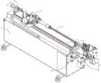
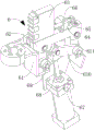
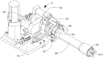
FIG. 1 is a schematic diagram of a main structure of a first embodiment of the present invention;
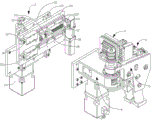
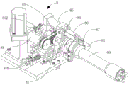
FIG. 2 is a schematic diagram showing a displacement structure and a separation structure of a pipe bending mechanism according to a first, second and third embodiment of the present invention;
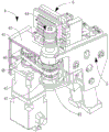
FIG. 3 is a schematic view of a first, second and third embodiment of the present invention with a partially cut-away view of the pipe bending mechanism;
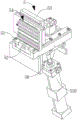
FIG. 4 is a schematic view showing the structure of the clamping mold part in the first, second and third embodiments of the present invention;
FIG. 5 is a schematic view showing the structure of the top clamping mold part in the first, second and third embodiments of the present invention;
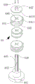
FIG. 6 is a schematic view of an exploded view of a first, second and third embodiment of the present invention;
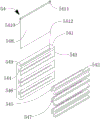
FIG. 7 is a schematic view of an exploded view of the clamping assembly in accordance with the first, second and third embodiments of the present invention;
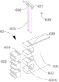
FIG. 8 is a schematic view of an explosion structure at the tightening assembly in the first, second and third embodiments of the present invention;
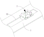
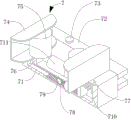
FIG. 9 is a schematic diagram of the structure of the deviation correcting and supporting assembly in the first, second and third embodiments of the present invention;
FIG. 10 is a schematic diagram showing a cross-sectional structure of a deviation correcting and supporting assembly according to a first, second and third embodiment of the present invention;
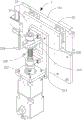
FIG. 11 is a schematic view showing the structure of a displacement structure according to the first, second and third embodiments of the present invention;
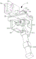
FIG. 12 is a schematic view showing a transmission structure of a clamping die part according to a third embodiment of the present invention;
FIG. 13 is a schematic view showing the structure of a feeding member according to a third embodiment of the present invention;
fig. 14 is a schematic view of a third embodiment of the present invention after the feeding member exits the housing.
In the figure: 1. a main frame; 2. a displacement structure; 3. a pipe bending mechanism; 4. a wheel mold part; 5. a clamping mold part; 6. a pressing die part; 7. a deviation rectifying and supporting component; 8. a feeding member; 11. a main slide rail; 12. a notch; 13. a support plate; 14. a cylinder; 15. a core rod sleeve; 21. a panel; 22. a vertical guide rail; 23. a vertical sliding seat; 24. an adjusting plate; 25. a transverse guide rail; 26. a horizontal sliding seat; 27. a transverse through groove; 28. a power plate; 29. a first gear motor; 210. a drive bevel gear; 211. a first screw rod; 212. a first threaded sleeve; 213. a driven bevel gear; 214. an inner plate; 215. a vertical through groove; 216. a lifting plate; 217. a second gear motor; 218. a second screw rod; 219. a second threaded sleeve; 41. a main board body; 42. a first frame; 43. a turntable; 44. a bent pipe assembly; 45. a third gear motor; 46. a drive sprocket; 47. a driven sprocket; 48. a drive chain; 441. a seat stand; 442. a profiled shaft; 443. a bent pipe grooved pulley; 444. a special-shaped hole; 445. a vertical rod; 446. a first jack; 447. a second jack; 448. a threaded column; 449. a nut; 4410. a top cover plate; 4411. a wheel mold groove plate; 51. a cross plate; 52. a sliding table; 53. a vertical plate; 54. a clamping assembly; 55. a first socket; 56. a first plunger; 57. a first locking bolt; 58. a second frame; 59. a through port; 510. a first hydraulic cylinder; 511. a special-shaped hinged support; 512. a rotating rod; 513. a driven hinged support; 541. a side plate; 542. clamping the groove plate; 543. positioning the notch; 544. a T-shaped groove; 545. a T-shaped strip; 546. a first port; 547. a second square opening; 548. installing a plugboard; 549. a top opening; 5410. a top strip; 5411. installing a bolt; 5412. a first threaded hole; 61. a third frame; 62. a mobile station; 63. a jacking component; 64. a second socket; 65. a second plunger; 66. a second locking bolt; 67. a second hydraulic cylinder; 68. a power hinged support; 69. a first link; 610. a second link; 613. a third link; 631. a plate body; 632. tightly pushing the groove plate; 633. a first through hole; 634. a second through hole; 635. inserting a column; 636. a clamping plate; 637. a threaded through hole; 638. a second threaded hole; 639. a side bolt; 6310. a mounting port; 71. a housing; 72. a clamping plate; 73. a third locking bolt; 74. a wheel seat; 75. deviation correcting wheels; 76. a slide bar; 77. a top sliding port; 78. a toothed plate; 79. a gear; 710. a return spring; 711. a riding wheel; 81. a slide plate seat; 82. a housing; 83. a feeding sleeve shaft; 84. an upper hinge support; 85. a third hydraulic cylinder; 86. a supporting rod; 87. a shifting fork; 88. a taper sleeve; 89. a fourth gear motor; 810. a driving pulley; 811. a driven pulley; 812. a transmission belt; 813. clamping jaw.
Description of the embodiments
The following description of the embodiments of the present invention will be made clearly and completely with reference to the accompanying drawings, in which it is apparent that the embodiments described are only some embodiments of the present invention, but not all embodiments. All other embodiments, which can be made by those skilled in the art based on the embodiments of the invention without making any inventive effort, are intended to be within the scope of the invention.
Examples
Referring to fig. 1-8, the present invention provides a technical solution: the full-automatic pipe bending machine comprises a main frame 1, wherein the top surface of the main frame 1 is fixedly connected with two main slide rails 11, the top surface of one side of the main frame 1 is vertically fixedly connected with a support plate 13, a cylinder 14 is fixedly connected to the support plate 13, one end of the cylinder 14 close to the feeding part 8 is fixedly connected with a core rod sleeve 15, one side of the main frame 1, which is far away from the support plate 13, is fixedly connected with a displacement structure 2, the displacement structure 2 is positioned at the outer side of the main frame 1 and fixedly connected with a pipe bending mechanism 3, the pipe bending mechanism 3 comprises a wheel mold part 4, a mold clamping part 5 and a mold jacking part 6, the wheel mold part 4 comprises a first frame 42, the top surface of the first frame 42 is rotationally connected with a turntable 43, the top surface of the turntable 43 is provided with a pipe bending assembly 44, the mold clamping part 5 comprises a transverse plate 51, the end part of the transverse plate 51 is fixedly connected to the top surface of the first frame 42, the top surface of the transverse plate 51 is movably connected with a sliding table 52, the top surface of the sliding table 52 is horizontally slidably connected with a vertical plate 53, the vertical plate 53 is fixedly connected with a clamping assembly 54 on one side of the wheel mold part 4, the mold part 6 comprises a third frame 61, the top surface of the third turntable 61 is fixedly connected to the outer side of the top surface of the turntable 43, the third frame 61 is movably connected with the top surface of the movable table 62, and the top surface of the movable table 62 is movably connected with the top surface of the movable table 62;
the elbow assembly 44 comprises a seat table 441 and a plurality of elbow grooved wheels 443, the seat table 441 is fixedly connected to the top surface of the turntable 43, the center position of the top surface of the seat table 441 is vertically fixedly connected with a special-shaped shaft 442, the center of the inner side of the elbow grooved wheels 443 is vertically provided with a special-shaped hole 444, the special-shaped holes 444 on the plurality of elbow grooved wheels 443 are sleeved on the outer side of the special-shaped shaft 442, the top end of the special-shaped shaft 442 is sleeved with a top cover plate 4410, the top surface of the seat table 441 is uniformly and vertically fixedly connected with a plurality of vertical rods 445 at the outer side of the special-shaped shaft 442, the plurality of elbow grooved wheels 443 are vertically provided with a plurality of first jacks 446 at the same vertical position of the plurality of elbow grooved wheels 443 corresponding to the plurality of vertical rods 445, the top cover plate 4410 is provided with a plurality of second jacks 447 corresponding to the same vertical position of the plurality of vertical rods 445, the vertical rods 445 pass through the plurality of first jacks 446 and the second jacks 447 and are fixedly connected with threaded columns 448, the threaded columns 448 are in threaded sleeves 449, one side of the elbow grooved wheels 443 is fixedly connected with a wheel mold groove plate 4411, and the elbow assembly 44 is simultaneously provided with the plurality of elbow grooved wheels 443;
the clamping assembly 54 comprises a side plate 541 and a plurality of clamping groove plates 542, wherein a plurality of positioning notches 543 are uniformly formed in one side of the side plate 541 close to the turntable 43, T-shaped grooves 544 are formed in the side walls of the positioning notches 543, T-shaped bars 545 are fixedly connected to the side walls of the clamping groove plates 542, the T-shaped bars 545 are inserted into the T-shaped grooves 544, second square openings 547 are vertically formed in the T-shaped bars 545, first square openings 546 are formed in the side plate 541 at the same vertical position corresponding to the second square openings 547, mounting inserting plates 548 are inserted into the first square openings 546 and the second square openings 547, top surfaces of the mounting inserting plates 548 are fixedly connected with top bars 5410, top openings 549 are formed in the top ends of the first square openings 546, the top bars 5410 are inserted into the top openings 549, two mounting bolts 5411 are vertically connected in a rotating mode, two first threaded holes 5412 are formed in the bottom surfaces of the two ends of the top openings 549, the mounting bolts 5411 are in threaded connection with the first threaded holes 5412, and the clamping assembly 54 is provided with a plurality of clamping groove plates 542 which can be matched with a plurality of grooved wheels 443;
the propping assembly 63 comprises a plate body 631 and a plurality of propping groove plates 632, the plate body 631 is slidably connected to the top surface of the moving table 62, a plurality of mounting holes 6310 are uniformly formed on one side, close to the turntable 43, of the plate body 631, the propping groove plates 632 are inserted in the mounting holes 6310, a plurality of second through holes 634 are vertically formed in the propping groove plates 632, the plate body 631 is positioned at the same vertical position of the plurality of second through holes 634, a plurality of first through holes 633 and a plurality of second through holes 634 are inserted in a plurality of inserting columns 635, top surfaces of the plurality of inserting columns 635 are fixedly connected with clamping plates 636, two sides of the clamping plates 636 are contacted with two sides of the top surface of the plate body 631, two threaded through holes 637 are formed on two sides of the clamping plates 636, two second threaded holes 638 are formed on two sides of the top surface of the plate body 631, a plurality of propping groove plates 632 are also arranged in the propping assembly 63 so as to be matched with a plurality of bent pipes 638 in a threaded connection mode.
Examples
Referring to fig. 2-11, in a second embodiment of the present invention, based on the previous embodiment, the displacement structure 2 includes a panel 21 fixedly connected to a side wall of the main frame 1, two vertical rails 22 are fixedly connected to a side of the panel 21 away from the main frame 1, a vertical sliding seat 23 is vertically slidably connected to the vertical rails 22, an adjusting plate 24 is fixedly connected to the vertical sliding seat 23, two horizontal rails 25 are horizontally fixedly connected to a side of the adjusting plate 24 away from the panel 21, a horizontal sliding seat 26 is slidably connected to the horizontal rails 25, a main board body 41 is fixedly connected to a side of the first frame 42, and the main board body 41 is fixedly connected to the horizontal sliding seat 26.
The inner plate 214 is fixedly connected to one side of the panel 21 in the main frame 1, the inner plate 214 and the panel 21 are vertically provided with a vertical through groove 215, the vertical through groove 215 is vertically connected with a lifting plate 216 in a sliding manner, the lifting plate 216 is fixedly connected to the side wall of the adjusting plate 24, the bottom surface of the inner plate 214 is fixedly connected with a second speed reducing motor 217, the rotating shaft end of the second speed reducing motor 217 is fixedly connected with a second screw rod 218, the lifting plate 216 is fixedly connected with a second threaded sleeve 219, the second screw rod 218 is in threaded connection with the second threaded sleeve 219, the second speed reducing motor 217 drives the second screw rod 218 to rotate, the adjusting plate 24 can be lifted and lowered, the pipe bending mechanism 3 is driven to lift, so that pipe bending grooved wheels 443, tight jacking grooved plates 632 and clamping grooved plates 542 at different height positions can be selected to perform pipe bending operation, the horizontal through groove 27 is horizontally formed in the adjusting plate 24, the power plate 28 is horizontally and dynamically connected in the horizontal through groove 27, the power plate 28 is fixedly connected with the main plate body 41, the outer side of the horizontal through groove 27 is horizontally and rotationally connected with the first screw rod 211, the power plate 28 is fixedly connected with the first threaded sleeve 212, the first screw rod 211 is in threaded connection with the first threaded sleeve 212, one side of the adjusting plate 24 is fixedly connected with the first gear motor 29, the rotating shaft end of the first gear motor 29 is fixedly connected with the driving bevel gear 210, the end part of the first screw rod 211 is fixedly connected with the driven bevel gear 213, the driving bevel gear 210 is in meshed connection with the driven bevel gear 213, and the first gear motor 29 is used for realizing fine adjustment of the horizontal position of the pipe bending mechanism 3.
The notch 12 is formed in the top surface of one side of the main frame 1, which is close to the pipe bending mechanism 3, the deviation rectifying and supporting component 7 is horizontally and movably connected in the notch 12, the deviation rectifying and supporting component 7 comprises a shell 71, two sides of the shell 71 are respectively and horizontally fixedly connected with two clamping plates 72, the clamping plates 72 are slidably sleeved at the edge of the notch 12, the top surfaces of the clamping plates 72 are in threaded connection with a third locking bolt 73, and the third locking bolt 73 is in contact with the top surface of the main frame 1.
The top surface of the shell 71 is horizontally provided with two top sliding ports 77, two sliding strips 76 are horizontally and movably connected in the two top sliding ports 77, the top surfaces of the two sliding strips 76 are respectively fixedly connected with two wheel seats 74, one sides of the two wheel seats 74 close to each other are respectively and rotatably connected with two deviation correcting wheels 75, the heights of the two sliding strips 76 are different, the bottom ends of the two sliding strips 76 are positioned in the shell 71 and are respectively and horizontally fixedly connected with two toothed plates 78, a gear 79 is rotatably connected between the two toothed plates 78 in the shell 71, the gear 79 is meshed and connected with the two toothed plates 78, two return springs 710 are respectively and fixedly connected between one sides of the two sliding strips 76 far away from each other and the end parts of the two top sliding ports 77, the center position of the top surface of the shell 71 is rotatably connected with a supporting wheel 711, under the action of the gear 79, the displacement of the two deviation correcting wheels 75 can occur in opposite directions, the stroke remains the same, and the limit on two sides of a pipe can be ensured when the pipe is clamped, and the two sides of the pipe can be positioned at the center of the two deviation correcting wheels 75.
Examples
Referring to fig. 2-14, in a third embodiment of the present invention, based on the two embodiments, the bottom surface of the first frame 42 is fixedly connected with a third gear motor 45, a rotating shaft end of the third gear motor 45 is located in the first frame 42 and fixedly connected with a driving sprocket 46, a rotating shaft end of the turntable 43 is located in the first frame 42 and fixedly connected with a driven sprocket 47, a transmission chain 48 is sleeved outside the driving sprocket 46 and the driven sprocket 47, and the third gear motor 45 realizes rotation of the turntable 43 to realize the pipe bending effect.
The bottom surface rigid coupling second frame 58 of diaphragm 51, second frame 58 bottom surface rotates and connects first pneumatic cylinder 510, first pneumatic cylinder 510 output top rigid coupling abnormal shape hinged support 511, abnormal shape hinged support 511 articulates bull stick 512, bull stick 512 free end articulates second frame 58, perpendicular through-hole 59 of seting up on the diaphragm 51, abnormal shape hinged support 511 articulates driven hinged support 513 one end, driven hinged support 513 passes through-hole 59 and rigid coupling slip table 52 bottom surface, during operation of first pneumatic cylinder 510, slip table 52 can be close to the tubular product, press from both sides tight tubular product, slip table 52 top surface rigid coupling first socket 55, first inserted link 56 is moved in the horizontal migration of first socket 55, first inserted link 56 tip rigid coupling riser 53 lateral wall, first socket 55 top surface threaded connection first locking bolt 57, first locking bolt 57 contacts first inserted link 56 surface, the horizontal position of convenient fine setting clamp assembly 54.
The bottom surface of third frame 61 rotates and connects second pneumatic cylinder 67, the top rigid coupling power hinge 68 of second pneumatic cylinder 67 output, power hinge 68 rotates and connects first connecting rod 69 and second connecting rod 610 one end, the first connecting rod 69 other end rotates and connects mobile station 62 bottom surface one end, the second connecting rod 610 other end rotates and connects third connecting rod 613 one end, the third connecting rod 613 other end rotates and connects mobile station 62 bottom surface other end, mobile station 62 top surface rigid coupling second socket 64, second socket 64 horizontal slip cup joints second inserted bar 65, second inserted bar 65 tip fixed plate body 631 lateral wall, second socket 64 top surface threaded connection second locking bolt 66, second locking bolt 66 bottom contact second inserted bar 65 surface, the horizontal position of convenient fine setting jack assembly 63.
The feeding component 8 comprises a sliding plate seat 81, the sliding plate seat 81 is connected with two main sliding rails 11 in a sliding manner, the top surface of the sliding plate seat 81 is fixedly connected with a casing 82, the casing 82 is rotationally connected with a feeding sleeve shaft 83, the feeding sleeve shaft 83 is sleeved with a taper sleeve 88 near the outer side of one end of the pipe bending mechanism 3, the circumference of the end part of the feeding sleeve shaft 83 is slidingly connected with a plurality of clamping jaws 813, the end part of the taper sleeve 88 is contacted with the outer side of the clamping jaws 813, the top surface of the casing 82 is fixedly connected with an upper hinge seat 84, the upper hinge seat 84 is rotationally connected with a third hydraulic cylinder 85, an output shaft of the third hydraulic cylinder 85 is fixedly connected with a supporting rod 86, the supporting rod 86 is rotationally connected with a shifting fork 87, the shifting fork 87 is rotationally connected with the outer side of the taper sleeve 88, a pipe is sleeved in the feeding sleeve shaft 83, and the fourth hydraulic cylinder 85 can drive the taper sleeve 88 to move when working, and the clamping jaws 813 can be used for clamping the pipe.
One side of the casing 82 is fixedly connected with a fourth gear motor 89, an output shaft of the fourth gear motor 89 is positioned in the casing 82 and fixedly connected with a driving belt pulley 810, a feeding sleeve shaft 83 is positioned in the casing 82, a driven belt pulley 811 is fixedly sleeved on the driving belt pulley 810 and the driven belt pulley 811, a transmission belt 812 is sleeved on the driving belt pulley 810 and the driven belt pulley 811, rotation of the feeding sleeve shaft 83 is achieved, and rotation of pipes is regulated.
Examples
Referring to fig. 1-14, in a fourth embodiment of the present invention, the present invention is based on the above three embodiments, when in use, a pipe is placed in a feeding sleeve 83, clamped by a clamping jaw 813, then the pipe end is sent into a pipe bending mechanism 3 by using an air cylinder 14 and a feeding component 8, the pipe enters a groove of a pipe bending groove wheel 443, meanwhile, a clamping component 54 in a clamping component 5 moves against the side wall of the pipe under the action of a first hydraulic cylinder 510, a tightening component 63 in a tightening component 6 moves against the pipe under the action of a second hydraulic cylinder 67, at this time, a tightening groove plate 632 and a wheel mold groove plate 4411 on the pipe bending groove wheel 443 are closed, the pipe is clamped, and then a turntable 43 rotates under the action of a third speed reducing motor 45, so as to realize pipe bending work; the pipe bending assembly 44 is provided with the pipe bending sheaves 443, the clamping assembly 54 is provided with the clamping groove plates 542, the jacking assembly 63 is provided with the jacking groove plates 632, and the pipe bending sheaves 443, the clamping groove plates 542 and the jacking groove plates 632 at different height positions can be adjusted to the pipe positions by matching with the lifting effect of the displacement structure 2, so that the pipe bending requirements of pipes with various diameters can be met, the operation requirements of rounding corners at different pipe bending positions can also be met, the adaptation force can be improved during single-batch operation, and the situation that the pipe bending sheaves 443 and the corresponding groove plates need to be replaced frequently during single-batch operation is avoided.
Although embodiments of the present invention have been shown and described, it will be understood by those skilled in the art that various changes, modifications, substitutions and alterations can be made therein without departing from the principles and spirit of the invention, the scope of which is defined in the appended claims and their equivalents.
Claims (10)
1. The utility model provides a full-automatic bending machine, includes main frame (1), two main slide rail (11) of main frame (1) top surface rigid coupling, two horizontal sliding connection pay-off part (8) on main slide rail (11), perpendicular rigid coupling extension board (13) of main frame (1) one side top surface, rigid coupling cylinder (14) on extension board (13), cylinder (14) are close to pay-off part (8) one end rigid coupling core bar cover (15), its characterized in that:
the novel plastic bending machine comprises a main frame (1), wherein one side of the main frame (1) is far away from a support plate (13), a displacement structure (2) is fixedly connected with a bent pipe mechanism (3) at the outer side of the main frame (1), the bent pipe mechanism (3) comprises a wheel mold part (4), a clamping mold part (5) and a jacking mold part (6), the wheel mold part (4) comprises a first frame (42), the top surface of the first frame (42) is rotationally connected with a turntable (43), the top surface of the turntable (43) is provided with a bent pipe assembly (44), the clamping mold part (5) comprises a transverse plate (51), the end part of the transverse plate (51) is fixedly connected with the top surface of the first frame (42), the top surface of the transverse plate (51) is movably connected with a sliding table (52), the top surface of the sliding table (52) is horizontally and slidably connected with a vertical plate (53), the vertical plate (53) is close to one side of the wheel mold part (4), the jacking mold part (6) comprises a third frame (61), the top surface of the third frame (61) is fixedly connected with the outer side of the turntable (43), and the top surface of the third frame (61) is movably connected with a movable table (62), and the top surface of the movable table (62) is movably connected with the movable table (63);
the pipe bending assembly (44) comprises a seat table (441) and a plurality of pipe bending grooved wheels (443), the seat table (441) is fixedly connected to the top surface of the rotary table (43), the center position of the top surface of the seat table (441) is vertically fixedly connected with a special-shaped shaft (442), the center of the inner side of the pipe bending grooved wheels (443) is vertically provided with a special-shaped hole (444), a plurality of special-shaped holes (444) on the pipe bending grooved wheels (443) are sleeved on the outer side of the special-shaped shaft (442), the top end of the special-shaped shaft (442) is sleeved with a top cover plate (4410), the top surface of the seat table (441) is uniformly and vertically fixedly connected with a plurality of vertical rods (445) at the outer side of the special-shaped shaft (442), a plurality of first jacks (446) are formed in the same vertical positions of the pipe bending grooved wheels (443), a plurality of second jacks (447) are formed in the same vertical positions of the top cover plate (4410) corresponding to the plurality of vertical rods (445), the vertical rods (445) penetrate through the first jacks (446) and the second jacks (448) and are fixedly connected with threaded columns (448), and the threaded columns (449) are fixedly connected with threaded columns (4411), and the threaded columns (4411) are fixedly connected with one side of the threaded columns (443);
the clamping assembly (54) comprises a side plate (541) and a plurality of clamping groove plates (542), wherein a plurality of positioning slots (543) are uniformly formed in one side, close to the turntable (43), of the side plate (541), T-shaped grooves (544) are formed in the side walls of the positioning slots (543), T-shaped strips (545) are fixedly connected to the side walls of the clamping groove plates (542), the T-shaped strips (545) are inserted into the T-shaped grooves (544), a second square opening (547) is vertically formed in the T-shaped strips (545), a first square opening (546) is formed in the side plate (541) corresponding to the second square opening (547) in the same vertical position, mounting inserting plates (548) are inserted into the first square opening (546) and the second square opening (547), top surfaces of the mounting inserting plates (548) are fixedly connected with top strips (5410), top openings (549) are formed in the top ends of the first square openings (546), the top strips (5410) are inserted into the top openings (549), two mounting bolts (5411) are vertically and rotatably connected to two sides of the top strips (5411), and two first threaded holes (5412) are formed in the first threaded holes (5412);
the tight subassembly (63) in top includes plate body (631) and a plurality of tight grooved plate (632) in top, plate body (631) sliding connection is at mobile station (62) top surface, a plurality of installing ports (6310) are evenly offered to plate body (631) near revolving stage (43) one side, tight grooved plate (632) are pegged graft in installing ports (6310), a plurality of second through-holes (634) are offered perpendicularly in tight grooved plate (632), plate body (631) are located a plurality of first through-holes (633) are offered in a plurality of second through-holes (634) same vertical position, a plurality of first through-holes (633) and a plurality of second through-holes (634) insert a plurality of inserted post (635), a plurality of inserted post (635) top surface rigid coupling cardboard (636), cardboard (636) both sides contact plate body (631) top surface both sides, two threaded through-holes (637) are offered to cardboard (636) both sides, two second threaded holes (638) are offered on plate body (631) top surface both sides, second threaded through-holes (638) and threaded bolt (639) side threaded connection bolt.
2. A fully automatic pipe bender according to claim 1, wherein: the displacement structure (2) comprises a panel (21) fixedly connected to the side wall of the main frame (1), two vertical guide rails (22) are fixedly connected to one side of the panel (21) away from the main frame (1), vertical sliding seats (23) are vertically and slidably connected to the vertical guide rails (22), regulating plates (24) are fixedly connected to the vertical sliding seats (23), two transverse guide rails (25) are horizontally and fixedly connected to one side of the regulating plates (24) away from the panel (21), transverse guide rails (26) are slidably connected to the transverse guide rails (25), a main board body (41) is fixedly connected to one side of the first frame (42), and the main board body (41) is fixedly connected to the transverse sliding seats (26).
3. A fully automatic pipe bender according to claim 2, wherein: the panel (21) is positioned on one side of the main frame (1) and fixedly connected with an inner plate (214), a vertical through groove (215) is vertically formed in the inner plate (214) and the panel (21), a lifting plate (216) is vertically and slidingly connected in the vertical through groove (215), the lifting plate (216) is fixedly connected on the side wall of an adjusting plate (24), a second speed reduction motor (217) is fixedly connected on the bottom surface of the inner plate (214), a second screw rod (218) is fixedly connected at the rotating shaft end of the second speed reduction motor (217), a second threaded sleeve (219) is fixedly connected in the lifting plate (216), a second screw rod (218) is in threaded connection with the second threaded sleeve (219), a horizontal through groove (27) is horizontally formed in the adjusting plate (24), a power plate (28) is fixedly connected with a main plate body (41), a first screw rod (211) is horizontally and rotationally connected with the outer side of the horizontal through groove (27), a first screw rod (211) is fixedly connected with a first threaded sleeve (212), the first screw rod (212) is in threaded connection with the first end of the first speed reduction motor (24), a bevel gear (29) is fixedly connected with the first end of the first screw rod (29), the drive bevel gear (210) is connected with the driven bevel gear (213) in a meshing manner.
4. A fully automatic pipe bender according to claim 1, wherein: notch (12) are offered to main frame (1) be close to return bend mechanism (3) one side top surface, horizontal movement connects in notch (12) and rectifies and hold up subassembly (7), rectify and hold up subassembly (7) including shell (71), two splint (72) of horizontal rigid coupling respectively in shell (71) both sides, splint (72) slip cup joint in notch (12) edge, splint (72) top surface threaded connection third locking bolt (73), third locking bolt (73) contact main frame (1) top surface.
5. The fully automatic pipe bender according to claim 4, wherein: two top sliding ports (77) are horizontally formed in the top surface of the shell (71), two sliding strips (76) are horizontally and movably connected in the top sliding ports (77), two top surfaces of the sliding strips (76) are fixedly connected with two wheel seats (74) respectively, two wheel seats (74) are mutually close to one side and are respectively connected with two deviation correcting wheels (75) in a rotating mode, the two sliding strips (76) are different in height, the bottom ends of the sliding strips (76) are located in the shell (71) and are respectively and horizontally fixedly connected with two toothed plates (78), a rotating connecting gear (79) is arranged between the two toothed plates (78) in the shell (71), the two toothed plates (78) are connected in a meshed mode, two reset springs (710) are fixedly connected between one side, away from each other, of the two sliding strips (76) and the end portions of the two top sliding ports (77), and the center position of the top surface of the shell (71) is rotatably connected with a supporting wheel (711).
6. A fully automatic pipe bender according to claim 1, wherein: the rotary table is characterized in that a third gear motor (45) is fixedly connected to the bottom surface of the first frame (42), the rotating shaft end of the third gear motor (45) is located in the first frame (42) and fixedly connected with a driving sprocket (46), the rotating shaft end of the rotary table (43) is located in the first frame (42) and fixedly connected with a driven sprocket (47), and a transmission chain (48) is sleeved on the outer sides of the driving sprocket (46) and the driven sprocket (47).
7. A fully automatic pipe bender according to claim 1, wherein: the utility model provides a horizontal plate (51) bottom surface rigid coupling second frame (58), first pneumatic cylinder (510) are connected in rotation of second frame (58) bottom surface, special-shaped hinged support (511) are connected on first pneumatic cylinder (510) output top rigid coupling, special-shaped hinged support (511) hinge bull stick (512), bull stick (512) free end hinge second frame (58), perpendicular opening (59) are offered on diaphragm (51), special-shaped hinged support (511) hinge driven hinged support (513) one end, driven hinged support (513) pass opening (59) and rigid coupling slip table (52) bottom surface, slip table (52) top surface rigid coupling first socket (55), horizontal moving in first socket (55) cup joints first inserted bar (56), first inserted bar (56) tip rigid coupling riser (53) lateral wall, first socket (55) top surface threaded connection first locking bolt (57), first locking bolt (57) contact first inserted bar (56) surface.
8. A fully automatic pipe bender according to claim 1, wherein: the third frame (61) bottom surface rotates and connects second pneumatic cylinder (67), second pneumatic cylinder (67) output top rigid coupling power hinge (68), power hinge (68) rotate and connect first connecting rod (69) and second connecting rod (610) one end, first connecting rod (69) other end rotates and connects mobile station (62) bottom surface one end, second connecting rod (610) other end rotates and connects third connecting rod (613) one end, third connecting rod (613) other end rotates and connects mobile station (62) bottom surface other end, mobile station (62) top surface rigid coupling second socket (64), second socket (64) horizontal slip cup joints second inserted bar (65), second inserted bar (65) tip fixed plate body (631) lateral wall, second socket (64) top surface threaded connection second locking bolt (66), second locking bolt (66) bottom contact second inserted bar (65) surface.
9. A fully automatic pipe bender according to claim 1, wherein: the feeding component (8) comprises a sliding plate seat (81), two main sliding rails (11) are connected with the sliding plate seat (81) in a sliding mode, a shell (82) is fixedly connected with the top surface of the sliding plate seat (81), a feeding sleeve shaft (83) is connected with the shell (82) in a rotating mode, a taper sleeve (88) is sleeved outside one end of the feeding sleeve shaft (83) close to a pipe bending mechanism (3), a plurality of clamping jaws (813) are connected with the circumference of the end portion of the feeding sleeve shaft (83) in a sliding mode, the end portion of the taper sleeve (88) is in contact with the outer side of the clamping jaws (813), a hinged support (84) is fixedly connected with the top surface of the shell (82), a third hydraulic cylinder (85) is connected with the upper hinged support (84) in a rotating mode, a shifting fork (87) is connected with the output shaft of the third hydraulic cylinder (85) in a fixed connection mode, and the shifting fork (87) is connected with the outer side of the taper sleeve (88) in a rotating mode.
10. The fully automatic pipe bender according to claim 9, wherein: the novel automatic feeding device is characterized in that a fourth gear motor (89) is fixedly connected to one side of the casing (82), an output shaft of the fourth gear motor (89) is located in the casing (82) and fixedly connected with a driving belt wheel (810), a feeding sleeve shaft (83) is located in the casing (82) and fixedly connected with a driven belt wheel (811), and a driving belt (812) is connected to the driving belt wheel (810) and the driven belt wheel (811) in a sleeved mode.
Priority Applications (1)
| Application Number | Priority Date | Filing Date | Title |
|---|---|---|---|
| CN202310383611.8A CN116274532A (en) | 2023-04-12 | 2023-04-12 | Full-automatic pipe bending machine |
Applications Claiming Priority (1)
| Application Number | Priority Date | Filing Date | Title |
|---|---|---|---|
| CN202310383611.8A CN116274532A (en) | 2023-04-12 | 2023-04-12 | Full-automatic pipe bending machine |
Publications (1)
| Publication Number | Publication Date |
|---|---|
| CN116274532A true CN116274532A (en) | 2023-06-23 |
Family
ID=86794207
Family Applications (1)
| Application Number | Title | Priority Date | Filing Date |
|---|---|---|---|
| CN202310383611.8A Withdrawn CN116274532A (en) | 2023-04-12 | 2023-04-12 | Full-automatic pipe bending machine |
Country Status (1)
| Country | Link |
|---|---|
| CN (1) | CN116274532A (en) |
Cited By (4)
| Publication number | Priority date | Publication date | Assignee | Title |
|---|---|---|---|---|
| CN118237499A (en) * | 2024-05-27 | 2024-06-25 | 龙口市通达油管有限公司 | Pipe bending equipment for engine oil pipe |
| CN118477924A (en) * | 2024-07-16 | 2024-08-13 | 江苏中创铝业科技有限公司 | Automatic pipe bending machine capable of feeding with follow-up and feeding method thereof |
| CN118595241A (en) * | 2024-07-31 | 2024-09-06 | 张家港市格雷斯机械有限公司 | A pipe bending device for pipes |
| CN120515858A (en) * | 2025-07-24 | 2025-08-22 | 湖北迪峰换热器股份有限公司 | A pipe bending equipment for heat exchanger production |
-
2023
- 2023-04-12 CN CN202310383611.8A patent/CN116274532A/en not_active Withdrawn
Cited By (5)
| Publication number | Priority date | Publication date | Assignee | Title |
|---|---|---|---|---|
| CN118237499A (en) * | 2024-05-27 | 2024-06-25 | 龙口市通达油管有限公司 | Pipe bending equipment for engine oil pipe |
| CN118477924A (en) * | 2024-07-16 | 2024-08-13 | 江苏中创铝业科技有限公司 | Automatic pipe bending machine capable of feeding with follow-up and feeding method thereof |
| CN118595241A (en) * | 2024-07-31 | 2024-09-06 | 张家港市格雷斯机械有限公司 | A pipe bending device for pipes |
| CN118595241B (en) * | 2024-07-31 | 2024-12-10 | 张家港市格雷斯机械有限公司 | Pipe bending equipment for pipe |
| CN120515858A (en) * | 2025-07-24 | 2025-08-22 | 湖北迪峰换热器股份有限公司 | A pipe bending equipment for heat exchanger production |
Similar Documents
| Publication | Publication Date | Title |
|---|---|---|
| CN113134527B (en) | Intelligent numerical control bending machine and bending processing method | |
| CN118808978B (en) | Positioning device and positioning method for welding three-way valve | |
| CN214719710U (en) | Stamping equipment for precision machining with guide structure | |
| CN215470405U (en) | Aluminum alloy extrusion side pipe inner wall burnishing device | |
| CN115173019A (en) | Waveguide processing apparatus | |
| CN222133523U (en) | A non-standard automatic drilling machine | |
| CN116441394B (en) | Adjustable stamping equipment is used in digit control machine tool processing | |
| CN219336035U (en) | Punching device for annular copper sheet | |
| CN213470334U (en) | Auxiliary clamp for workbench of control machine tool | |
| CN212918253U (en) | Thin-wall cylinder assembling and welding fixture | |
| CN213857477U (en) | High-precision large-scale double-servo tapping machine tool for two side faces of cylinder body | |
| CN213226025U (en) | Automatic device of screwing up of hydraulic cylinder uide bushing | |
| CN115972601A (en) | A Twisting Cap Device for Improving Assembly Efficiency | |
| CN115179064A (en) | Agricultural machinery gear box machining center | |
| CN223616898U (en) | Automatic clamping mechanism for numerical control drilling and tapping machine | |
| CN218476325U (en) | Adjustable workbench for drilling machine | |
| CN219027082U (en) | Polishing equipment for machining mechanical parts | |
| CN219074065U (en) | Positioning device for stamping plate of press machine | |
| CN222511563U (en) | A round belt wheel batch drilling device | |
| CN116037982B (en) | Metal product processing device and processing method | |
| CN220863766U (en) | Cylinder bottom processing clamp | |
| CN220782743U (en) | Fixing device for spot welding of aluminum alloy workpiece | |
| CN223749109U (en) | Automatic change clamp location processingequipment | |
| CN222100032U (en) | Steel heat treatment quenching lifting appliance | |
| CN222199911U (en) | Deburring device for part machining |
Legal Events
| Date | Code | Title | Description |
|---|---|---|---|
| PB01 | Publication | ||
| PB01 | Publication | ||
| SE01 | Entry into force of request for substantive examination | ||
| SE01 | Entry into force of request for substantive examination | ||
| WW01 | Invention patent application withdrawn after publication | ||
| WW01 | Invention patent application withdrawn after publication |
Application publication date: 20230623 |