CN116267064A - Multifunctional transplanter for tobacco - Google Patents
Multifunctional transplanter for tobacco Download PDFInfo
- Publication number
- CN116267064A CN116267064A CN202310195433.6A CN202310195433A CN116267064A CN 116267064 A CN116267064 A CN 116267064A CN 202310195433 A CN202310195433 A CN 202310195433A CN 116267064 A CN116267064 A CN 116267064A
- Authority
- CN
- China
- Prior art keywords
- seedling
- transplanting
- sprocket
- crank
- frame
- Prior art date
- Legal status (The legal status is an assumption and is not a legal conclusion. Google has not performed a legal analysis and makes no representation as to the accuracy of the status listed.)
- Granted
Links
Images


Classifications
-
- A—HUMAN NECESSITIES
- A01—AGRICULTURE; FORESTRY; ANIMAL HUSBANDRY; HUNTING; TRAPPING; FISHING
- A01B—SOIL WORKING IN AGRICULTURE OR FORESTRY; PARTS, DETAILS, OR ACCESSORIES OF AGRICULTURAL MACHINES OR IMPLEMENTS, IN GENERAL
- A01B49/00—Combined machines
- A01B49/04—Combinations of soil-working tools with non-soil-working tools, e.g. planting tools
- A01B49/06—Combinations of soil-working tools with non-soil-working tools, e.g. planting tools for sowing or fertilising
- A01B49/065—Combinations of soil-working tools with non-soil-working tools, e.g. planting tools for sowing or fertilising the soil-working tools being actively driven
-
- A—HUMAN NECESSITIES
- A01—AGRICULTURE; FORESTRY; ANIMAL HUSBANDRY; HUNTING; TRAPPING; FISHING
- A01B—SOIL WORKING IN AGRICULTURE OR FORESTRY; PARTS, DETAILS, OR ACCESSORIES OF AGRICULTURAL MACHINES OR IMPLEMENTS, IN GENERAL
- A01B33/00—Tilling implements with rotary driven tools, e.g. in combination with fertiliser distributors or seeders, with grubbing chains, with sloping axles, with driven discs
- A01B33/02—Tilling implements with rotary driven tools, e.g. in combination with fertiliser distributors or seeders, with grubbing chains, with sloping axles, with driven discs with tools on horizontal shaft transverse to direction of travel
- A01B33/021—Tilling implements with rotary driven tools, e.g. in combination with fertiliser distributors or seeders, with grubbing chains, with sloping axles, with driven discs with tools on horizontal shaft transverse to direction of travel with rigid tools
-
- A—HUMAN NECESSITIES
- A01—AGRICULTURE; FORESTRY; ANIMAL HUSBANDRY; HUNTING; TRAPPING; FISHING
- A01B—SOIL WORKING IN AGRICULTURE OR FORESTRY; PARTS, DETAILS, OR ACCESSORIES OF AGRICULTURAL MACHINES OR IMPLEMENTS, IN GENERAL
- A01B33/00—Tilling implements with rotary driven tools, e.g. in combination with fertiliser distributors or seeders, with grubbing chains, with sloping axles, with driven discs
- A01B33/08—Tools; Details, e.g. adaptations of transmissions or gearings
-
- A—HUMAN NECESSITIES
- A01—AGRICULTURE; FORESTRY; ANIMAL HUSBANDRY; HUNTING; TRAPPING; FISHING
- A01B—SOIL WORKING IN AGRICULTURE OR FORESTRY; PARTS, DETAILS, OR ACCESSORIES OF AGRICULTURAL MACHINES OR IMPLEMENTS, IN GENERAL
- A01B35/00—Other machines for working soil
- A01B35/18—Other machines for working soil with both rotating and non-rotating tools
-
- A—HUMAN NECESSITIES
- A01—AGRICULTURE; FORESTRY; ANIMAL HUSBANDRY; HUNTING; TRAPPING; FISHING
- A01B—SOIL WORKING IN AGRICULTURE OR FORESTRY; PARTS, DETAILS, OR ACCESSORIES OF AGRICULTURAL MACHINES OR IMPLEMENTS, IN GENERAL
- A01B35/00—Other machines for working soil
- A01B35/20—Tools; Details
- A01B35/22—Non-rotating tools; Resilient or flexible mounting of rigid tools
- A01B35/26—Rigid tools
-
- A—HUMAN NECESSITIES
- A01—AGRICULTURE; FORESTRY; ANIMAL HUSBANDRY; HUNTING; TRAPPING; FISHING
- A01B—SOIL WORKING IN AGRICULTURE OR FORESTRY; PARTS, DETAILS, OR ACCESSORIES OF AGRICULTURAL MACHINES OR IMPLEMENTS, IN GENERAL
- A01B49/00—Combined machines
- A01B49/02—Combined machines with two or more soil-working tools of different kind
- A01B49/022—Combined machines with two or more soil-working tools of different kind at least one tool being actively driven
-
- A—HUMAN NECESSITIES
- A01—AGRICULTURE; FORESTRY; ANIMAL HUSBANDRY; HUNTING; TRAPPING; FISHING
- A01B—SOIL WORKING IN AGRICULTURE OR FORESTRY; PARTS, DETAILS, OR ACCESSORIES OF AGRICULTURAL MACHINES OR IMPLEMENTS, IN GENERAL
- A01B49/00—Combined machines
- A01B49/02—Combined machines with two or more soil-working tools of different kind
- A01B49/022—Combined machines with two or more soil-working tools of different kind at least one tool being actively driven
- A01B49/025—Combined machines with two or more soil-working tools of different kind at least one tool being actively driven about a substantially vertical axis
-
- A—HUMAN NECESSITIES
- A01—AGRICULTURE; FORESTRY; ANIMAL HUSBANDRY; HUNTING; TRAPPING; FISHING
- A01B—SOIL WORKING IN AGRICULTURE OR FORESTRY; PARTS, DETAILS, OR ACCESSORIES OF AGRICULTURAL MACHINES OR IMPLEMENTS, IN GENERAL
- A01B49/00—Combined machines
- A01B49/04—Combinations of soil-working tools with non-soil-working tools, e.g. planting tools
-
- A—HUMAN NECESSITIES
- A01—AGRICULTURE; FORESTRY; ANIMAL HUSBANDRY; HUNTING; TRAPPING; FISHING
- A01C—PLANTING; SOWING; FERTILISING
- A01C11/00—Transplanting machines
- A01C11/006—Other parts or details or planting machines
-
- A—HUMAN NECESSITIES
- A01—AGRICULTURE; FORESTRY; ANIMAL HUSBANDRY; HUNTING; TRAPPING; FISHING
- A01C—PLANTING; SOWING; FERTILISING
- A01C11/00—Transplanting machines
- A01C11/02—Transplanting machines for seedlings
-
- A—HUMAN NECESSITIES
- A01—AGRICULTURE; FORESTRY; ANIMAL HUSBANDRY; HUNTING; TRAPPING; FISHING
- A01C—PLANTING; SOWING; FERTILISING
- A01C11/00—Transplanting machines
- A01C11/02—Transplanting machines for seedlings
- A01C11/025—Transplanting machines using seedling trays; Devices for removing the seedlings from the trays
-
- A—HUMAN NECESSITIES
- A01—AGRICULTURE; FORESTRY; ANIMAL HUSBANDRY; HUNTING; TRAPPING; FISHING
- A01C—PLANTING; SOWING; FERTILISING
- A01C15/00—Fertiliser distributors
-
- A—HUMAN NECESSITIES
- A01—AGRICULTURE; FORESTRY; ANIMAL HUSBANDRY; HUNTING; TRAPPING; FISHING
- A01C—PLANTING; SOWING; FERTILISING
- A01C15/00—Fertiliser distributors
- A01C15/16—Fertiliser distributors with means for pushing out the fertiliser, e.g. by a roller
-
- A—HUMAN NECESSITIES
- A01—AGRICULTURE; FORESTRY; ANIMAL HUSBANDRY; HUNTING; TRAPPING; FISHING
- A01C—PLANTING; SOWING; FERTILISING
- A01C5/00—Making or covering furrows or holes for sowing, planting or manuring
- A01C5/04—Machines for making or covering holes for sowing or planting
-
- A—HUMAN NECESSITIES
- A01—AGRICULTURE; FORESTRY; ANIMAL HUSBANDRY; HUNTING; TRAPPING; FISHING
- A01G—HORTICULTURE; CULTIVATION OF VEGETABLES, FLOWERS, RICE, FRUIT, VINES, HOPS OR SEAWEED; FORESTRY; WATERING
- A01G13/00—Protection of plants
- A01G13/30—Ground coverings
- A01G13/37—Arrangements for laying out or removing ground coverings
-
- A—HUMAN NECESSITIES
- A01—AGRICULTURE; FORESTRY; ANIMAL HUSBANDRY; HUNTING; TRAPPING; FISHING
- A01G—HORTICULTURE; CULTIVATION OF VEGETABLES, FLOWERS, RICE, FRUIT, VINES, HOPS OR SEAWEED; FORESTRY; WATERING
- A01G13/00—Protection of plants
- A01G13/30—Ground coverings
- A01G13/38—Anchoring means for ground coverings
-
- A—HUMAN NECESSITIES
- A01—AGRICULTURE; FORESTRY; ANIMAL HUSBANDRY; HUNTING; TRAPPING; FISHING
- A01G—HORTICULTURE; CULTIVATION OF VEGETABLES, FLOWERS, RICE, FRUIT, VINES, HOPS OR SEAWEED; FORESTRY; WATERING
- A01G25/00—Watering gardens, fields, sports grounds or the like
- A01G25/09—Watering arrangements making use of movable installations on wheels or the like
Landscapes
- Life Sciences & Earth Sciences (AREA)
- Environmental Sciences (AREA)
- Soil Sciences (AREA)
- Engineering & Computer Science (AREA)
- Mechanical Engineering (AREA)
- Health & Medical Sciences (AREA)
- General Health & Medical Sciences (AREA)
- Toxicology (AREA)
- Water Supply & Treatment (AREA)
- Transplanting Machines (AREA)
Abstract
本发明涉及烟草移栽技术领域,具体涉及一种烟草用多功能移栽机,可以实现旋耕、起垄、打塘、栽植、浇水、施肥以及覆膜等多个工序的集成作业,操作更加方便,大幅度减少了人工栽植参与,多环节作业中均提高了工作效率,并且可以减少秧苗的损伤,改善秧苗的成活率。所述打塘装置、移栽装置、浇水装置、环状施肥装置依次之间的间距相等均为一个株距,有效改善株距不一致问题;通过打塘装置和移栽装置改进后,可以保证秧苗在栽植过程中保持直立状态,保证秧苗成活率;通过对浇水装置进行改进后可以实现定量定点浇水,根据不同秧苗进行调整,适用性更强,同时环形施肥口和环形浇水口可以对秧苗进行保护,减少对秧苗的损伤,提高成活率。
The invention relates to the technical field of tobacco transplanting, in particular to a multifunctional tobacco transplanting machine, which can realize the integrated operation of multiple processes such as rotary tillage, ridging, pond making, planting, watering, fertilizing, and film covering. It is more convenient, greatly reduces the participation of manual planting, improves work efficiency in multi-link operations, and can reduce damage to seedlings and improve the survival rate of seedlings. The spacing between the pond-making device, transplanting device, watering device, and annular fertilizing device is equal to one plant distance, which effectively improves the problem of inconsistent plant-to-plant spacing; after the improvement of the pond-making device and transplanting device, it can ensure that the seedlings are in the same position. Keep upright during the planting process to ensure the survival rate of seedlings; through the improvement of the watering device, quantitative and fixed-point watering can be realized, adjusted according to different seedlings, and the applicability is stronger. Carry out protection, reduce the damage to rice seedling, improve survival rate.
Description
技术领域technical field
本发明涉及烟草移栽技术领域,具体涉及一种烟草用多功能移栽机。The invention relates to the technical field of tobacco transplanting, in particular to a multifunctional transplanting machine for tobacco.
背景技术Background technique
我国的烟草种植面积广泛,产量居世界首位,占世界总产量的30%左右,因此秧苗移栽的需求较大,同时为了更好的保证秧苗的成活率,移栽过程中通常包括秧苗移栽、浇水、施肥等多项作业过程。但是由于我国的移栽设备研发起步较晚,目前我国旱地移栽大多仍然依靠人工完成,如按照株距人工进行刨坑并进行栽种、施肥等工作,人工移栽方式劳动强度较大,费时费力,效率较低;或现有技术中也有采用移栽机辅助作业,但目前移栽机多为半自动移栽机即仅能完成其中为数不多的一项或两项作业,且移栽质量得不到较好的保障,在移栽过程中容易出现损伤秧苗、秧苗的直立度不够、秧苗株距与深度不一致的情况,影响秧苗移栽效率和成活情况。因此现有技术中烟草移栽机有待进一步改进。my country's tobacco planting area is extensive, and its output ranks first in the world, accounting for about 30% of the world's total output. Therefore, the demand for transplanting rice seedlings is relatively large. At the same time, in order to better ensure the survival rate of seedlings, the transplanting process usually includes transplanting , watering, fertilizing and many other operations. However, due to the late start of research and development of transplanting equipment in my country, most of the dry land transplanting in my country still relies on manual work. For example, manual digging, planting, fertilization, etc. are carried out according to the distance between plants. Manual transplanting is labor-intensive and time-consuming. Efficiency is lower; Or also have to adopt transplanting machine auxiliary operation in the prior art, but at present transplanting machine mostly is semi-automatic transplanting machine and promptly can only finish one or two operations wherein few in number, and transplanting quality is not enough. In the process of transplanting, it is easy to damage the seedlings, the uprightness of the seedlings is not enough, and the spacing and depth of the seedlings are inconsistent, which will affect the transplanting efficiency and survival of the seedlings. Therefore tobacco transplanting machine in the prior art needs further improvement.
发明内容Contents of the invention
本发明的目的在于提供一种烟草用多功能移栽机,以解决上述背景技术中存在的现有技术问题。The object of the present invention is to provide a multi-functional transplanter for tobacco to solve the existing technical problems in the above-mentioned background technology.
为解决上述的技术问题,本发明提供的技术方案为:提供了一种烟草用多功能移栽机,包括机架、地轮、旋耕起垄装置、打塘装置、移栽装置、秧苗输送装置、苗盘输送装置、苗盘回收装置、浇水装置、环状施肥装置以及覆膜覆土装置,所述机架首端设置有悬挂架,所述地轮对称设置在机架底端且后轮旋转提供动力;所述旋耕起垄装置设置在机架的一端且位于悬挂架的一侧,用于对土壤进行破土起垄;所述打塘装置、移栽装置依次设置旋耕起垄装置后端的机架上,用于打塘和秧苗移栽;所述秧苗输送装置设置在移栽装置的上方,用于多秧苗连续输送至移栽装置,所述苗盘输送装置设置在秧苗输送装置的一侧,用于输送装有秧苗的苗盘,所述苗盘回收装置设置在苗盘输送装置的下方,用于苗盘的回收;所述浇水装置、环状施肥装置依次设置在移栽装置的后端,用于对移栽后的秧苗进行浇水和施肥;所述覆膜覆土装置设置机架末端,用于秧苗的覆膜和覆土作业。In order to solve the above-mentioned technical problems, the technical solution provided by the present invention is: a multifunctional transplanter for tobacco is provided, including a frame, a ground wheel, a rotary tillage ridging device, a pond making device, a transplanting device, and a seedling transporting device. device, seedling tray conveying device, seedling tray recovery device, watering device, annular fertilization device and film and soil covering device, the head end of the frame is provided with a suspension frame, and the ground wheels are symmetrically arranged at the bottom of the frame and rear Wheel rotation provides power; the rotary tillage and ridging device is arranged at one end of the frame and on one side of the suspension frame, and is used to break and rid the soil; On the frame at the rear end of the device, it is used for making ponds and transplanting rice shoots; the seedling conveying device is arranged above the transplanting device, and is used for continuously conveying multiple seedlings to the transplanting device, and the seedling tray conveying device is arranged on the seedling conveying device. One side of the device is used to transport the seedling trays with seedlings, and the seedling tray recovery device is arranged under the seedling tray conveying device for the recovery of the seedling trays; the watering device and the annular fertilization device are arranged in sequence The rear end of the transplanting device is used for watering and fertilizing the transplanted seedlings; the film-covering and soil-covering device is provided at the end of a frame for film-covering and soil-covering operations of the seedlings.
优选的,所述打塘装置包括第一安装板、第一曲柄连杆机构、打塘电机以及打塘钻头,所述第一安装板固定设置在机架上且位于旋耕起垄装置的一侧,所述第一曲柄连杆机构设置在第一安装板上且由动力装置驱动运动,所述打塘电机由第一曲柄连杆机构驱动上下运动,所述打塘钻头由打塘电机驱动转动。Preferably, the pond-making device includes a first mounting plate, a first crank-link mechanism, a pond-making motor and a pond-making drill bit, and the first mounting plate is fixedly arranged on the frame and located on one side of the rotary tillage and ridging device. On the other hand, the first crank-link mechanism is arranged on the first mounting plate and is driven by the power device to move, the pond-making motor is driven to move up and down by the first crank-link mechanism, and the pond-making drill bit is driven by the pond-making motor turn.
优选的,所述动力装置包括地轮链轮、传动链轮、第一链轮、第二链轮以及第三链轮,所述地轮链轮与地轮同轴设置同步转动,所述传动链轮通过链条由地轮链轮驱动转动且套设在动力轴上,所述动力轴一端转动连接在机架上,另一端连接有第一链轮,所述第一链轮、第二链轮、第三链轮均转动连接在第一安装板上且相互之间通过链条连接;Preferably, the power device includes a ground wheel sprocket, a transmission sprocket, a first sprocket, a second sprocket and a third sprocket, the ground wheel sprocket and the ground wheel are arranged to rotate synchronously, and the transmission The sprocket is driven to rotate by the ground wheel sprocket through the chain and is sleeved on the power shaft. One end of the power shaft is rotatably connected to the frame, and the other end is connected to the first sprocket. The first sprocket, the second chain The wheel and the third sprocket are both rotatably connected to the first mounting plate and connected to each other through a chain;
所述第一曲柄连杆机构包括主动曲柄、横杆、连杆以及从动曲柄,所述主动曲柄一端同轴设置在第二链轮上且驱动主动曲柄转动,另一端与横杆的一端铰接,所述横杆的另一端固定设置有打塘电机,所述连杆的底端铰接在横杆上,顶端与从动曲柄一端铰接,从动曲柄的另一端同轴设置在第三链轮上且驱动从动曲柄转动。The first crank linkage mechanism includes a driving crank, a cross bar, a connecting rod and a driven crank, one end of the driving crank is coaxially arranged on the second sprocket and drives the driving crank to rotate, and the other end is hinged to one end of the cross bar , the other end of the cross bar is fixedly equipped with a motor for making ponds, the bottom end of the connecting rod is hinged on the cross bar, the top end is hinged with one end of the driven crank, and the other end of the driven crank is coaxially arranged on the third sprocket and drive the driven crank to rotate.
优选的,所述移栽装置包括第二安装板、第二曲柄连杆机构、鸭嘴式移栽筒、凸轮以及拉杆,所述第二曲柄连杆机构设置在第二安装板上且由打塘装置通过第一联动机构驱动运动,所述第二曲柄连杆机构与第一曲柄连杆机构结构相同,所述鸭嘴式移栽筒由第二曲柄连杆机构驱动上下运动,所述鸭嘴式移栽筒顶端设置有接苗筒,底端由对称设置的鸭嘴片扣合形成,所述凸轮与第二曲柄连杆机构的第三链轮同轴设置且驱动转动,所述拉杆铰接在第二安装板上且设置在凸轮一侧,所述拉杆通过拉线与鸭嘴片连接。Preferably, the transplanting device includes a second mounting plate, a second crank link mechanism, a duckbill transplanting cylinder, a cam and a pull rod, the second crank link mechanism is arranged on the second mounting plate and is driven by a The pond device is driven to move by the first linkage mechanism. The second crank-link mechanism has the same structure as the first crank-link mechanism. The duckbill transplanting cylinder is driven to move up and down by the second crank-link mechanism. The top of the mouth-type transplanting tube is provided with a seedling tube, and the bottom end is formed by buckling symmetrically arranged duckbill pieces. The cam is coaxially set and driven to rotate with the third sprocket of the second crank linkage mechanism. The pull rod Hinged on the second mounting plate and arranged on one side of the cam, the pull rod is connected with the duckbill piece through a pull wire.
优选的,所述秧苗输送装置包括苗筒转盘、苗筒、上挡圈、下挡圈以及导苗筒,所述苗筒转盘通过换向箱与第二联动机构由移栽装置驱动转动,所述苗筒沿苗筒转盘周向均匀设置有多个,所述苗筒转盘的外侧壁与苗筒外侧壁结构相适配且带动苗筒转动,所述上挡圈套设置多个苗筒的外侧,所述下挡圈固定设置在机架上且设置有空段部,所述导苗筒对应设置在空段部的下方。Preferably, the seedling conveying device includes a seedling tube turntable, a seedling tube, an upper retaining ring, a lower retaining ring and a seedling guide tube, and the seedling tube turntable is driven to rotate by the transplanting device through a reversing box and a second linkage mechanism, so that A plurality of seedling tubes are evenly arranged along the circumference of the seedling tube turntable, the outer wall of the seedling tube turntable is adapted to the structure of the outer wall of the seedling tube and drives the seedling tube to rotate, and the upper retaining ring is set on the outer side of a plurality of seedling tubes. , the lower retaining ring is fixedly arranged on the frame and is provided with an empty section, and the seedling guide tube is correspondingly arranged below the empty section.
优选的,所述苗盘输送装置包括侧端板、移动平台、移动机构、传动机构以及挡杆,所述侧端板对称设置在机架上,所述侧端板之间固定设置有支撑架,所述移动平台通过移动机构在与支撑架上滑动连接,所述传动机构设置在侧端板上且驱动档杆移动。Preferably, the seedling tray conveying device includes a side end plate, a mobile platform, a moving mechanism, a transmission mechanism and a blocking rod, the side end plates are symmetrically arranged on the frame, and a support frame is fixedly arranged between the side end plates , the mobile platform is slidably connected to the support frame through a moving mechanism, and the transmission mechanism is arranged on the side end plate and drives the gear lever to move.
优选的,所述苗盘回收装置包括第一导向板、传动带机构、第二导向板以及回收箱,所述传送带机构设置在苗盘输送装置的下方且传送带与机架转动连接,所述第一导向板设置在传送带的首端,所述第二导向板设置在传送带的末端,所述第一导向板与第二导向板均与传送带倾斜设置,所述回收箱设置在第二导向板的末端。Preferably, the seedling tray recovery device includes a first guide plate, a transmission belt mechanism, a second guide plate and a recovery box, the conveyor belt mechanism is arranged below the seedling tray conveying device and the conveyor belt is rotatably connected to the frame, and the first The guide plate is arranged at the head end of the conveyor belt, the second guide plate is arranged at the end of the conveyor belt, the first guide plate and the second guide plate are both inclined to the conveyor belt, and the recovery box is arranged at the end of the second guide plate .
优选的,所述浇水装置包括泵体、进水弹簧、进水阀球、出水阀球、出水弹簧、活塞以及驱动机构,所述泵体上设置有进水口与出水口,所述进水口与泵体内第一腔室连通,所述进水弹簧底端固定设置在第一腔室内侧壁上,顶端固定设置有进水阀球,所述进水阀球抵接在进水口末端;所述出水口与第二腔室连通,所述出水阀球顶端抵接在第一腔室与第二腔室之间,所述出水弹簧一端固定设置在出水阀球上,另一端固定设置在第二腔室的内侧壁上;所述活塞与第一腔室滑动连接且由驱动机构驱动滑动。Preferably, the watering device includes a pump body, a water inlet spring, a water inlet valve ball, a water outlet valve ball, a water outlet spring, a piston and a driving mechanism, the pump body is provided with a water inlet and a water outlet, and the water inlet It communicates with the first chamber in the pump body, the bottom end of the water inlet spring is fixedly arranged on the inner side wall of the first chamber, and the top end is fixedly arranged with a water inlet valve ball, and the water inlet valve ball abuts against the end of the water inlet; The water outlet is in communication with the second chamber, the top of the water outlet valve ball abuts between the first chamber and the second chamber, one end of the water outlet spring is fixedly arranged on the water outlet valve ball, and the other end is fixedly arranged on the second chamber. On the inner side wall of the second chamber; the piston is slidably connected with the first chamber and driven to slide by the driving mechanism.
优选的,所述浇水装置包括水箱一、存水仓以及拨水轮,所述水箱一固定设置在机架上,所述存水仓首端与水箱一连接,末端设置有浇水口,所述拨水轮转动设置在存水仓内且由驱动电机驱动转动。Preferably, the watering device includes a
优选的,所述环状施肥装置包括肥料箱、分肥箱、施肥管以及环状施肥口,所述分肥箱贯通连接在肥料箱的底端,所述施肥管一端连接在分肥箱上,另一端设置在环状施肥口上,所述环状施肥口上设置有凸缘,所述施肥管的末端抵接在凸缘上,所述施肥管上还设置有带动施肥管上下运动的提拉机构。Preferably, the annular fertilization device includes a fertilizer box, a fertilizer distribution box, a fertilization pipe and an annular fertilization opening, the fertilizer distribution box is connected through the bottom end of the fertilizer box, and one end of the fertilization pipe is connected to the fertilizer distribution box , the other end is set on the ring-shaped fertilization port, the ring-shaped fertilization port is provided with a flange, the end of the fertilization pipe is abutted on the flange, and the fertilization pipe is also provided with a lifting device that drives the fertilization pipe to move up and down. mechanism.
本发明提供的技术方案产生的有益效果在于:The beneficial effect that the technical solution provided by the invention produces is:
本发明提供的移栽机,实现旋耕、起垄、打塘、栽植、浇水、施肥以及覆膜等多个工序的集成作业,操作更加方便,大幅度减少了人工栽植参与,多环节作业中均提高了工作效率,并且可以减少秧苗的损伤,改善秧苗的成活率。所述打塘装置、移栽装置、浇水装置、环状施肥装置依次之间的间距相等均为一个株距,有效改善株距不一致问题;通过打塘装置和移栽装置改进后,可以保证秧苗在栽植过程中保持直立状态,保证秧苗成活率;通过对浇水装置进行改进后可以实现定量定点浇水,移栽完成后根据株距进行定点浇水,出水量根据不同秧苗进行调整控制,适用性更强,同时环形施肥口和环形浇水口可以对秧苗进行保护,减少对秧苗的损伤,提高成活率。The transplanting machine provided by the present invention realizes the integrated operation of multiple processes such as rotary tillage, ridging, pond making, planting, watering, fertilizing, and film covering, and is more convenient to operate, greatly reducing the participation of manual planting, and multi-link operations Both improve the working efficiency, reduce the damage of seedlings, and improve the survival rate of seedlings. The spacing between the pond-making device, transplanting device, watering device, and annular fertilizing device is equal to one plant distance, which effectively improves the problem of inconsistent plant-to-plant spacing; after the improvement of the pond-making device and transplanting device, it can ensure that the seedlings are in the same position. Maintain an upright state during the planting process to ensure the survival rate of seedlings; through the improvement of the watering device, quantitative fixed-point watering can be realized. After transplanting, fixed-point watering is performed according to the distance between the plants, and the water output is adjusted and controlled according to different seedlings. The applicability is more Strong, and at the same time, the ring-shaped fertilization port and the ring-shaped watering port can protect the seedlings, reduce damage to the seedlings, and improve the survival rate.
附图说明Description of drawings
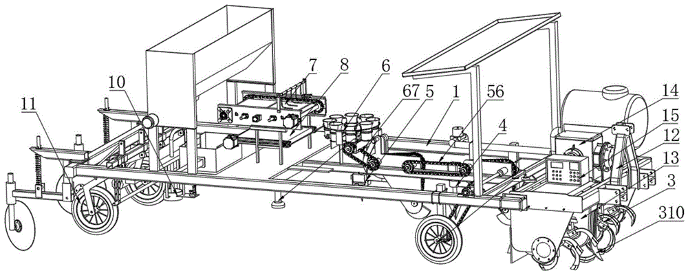
图1是本发明的整体结构示意图;Fig. 1 is the overall structural representation of the present invention;
图2是本发明中旋耕起垄装置的结构示意图;Fig. 2 is the structural representation of rotary tillage ridge-riding device in the present invention;
图3是本发明中打塘装置、移栽装置、秧苗输送装置、苗盘输送装置以及苗盘回收装置的立体结构示意图;Fig. 3 is the three-dimensional structure schematic diagram of pond making device, transplanting device, seedling conveying device, seedling tray conveying device and seedling tray recovery device in the present invention;
图4是本发明中打塘装置、移栽装置、秧苗输送装置、苗盘输送装置以及苗盘回收装置另一角度的立体结构示意图;Fig. 4 is a three-dimensional structural schematic view of another angle of the pond making device, the transplanting device, the seedling conveying device, the seedling tray conveying device and the seedling tray recovery device in the present invention;
图5是本发明中秧苗输送装置的结构示意图;Fig. 5 is the structural representation of rice shoot conveying device among the present invention;
图6是本发明中苗盘输送装置以及苗盘回收装置的结构示意图;Fig. 6 is the structural representation of seedling tray conveying device and seedling tray recovery device in the present invention;
图7是本发明中苗盘输送装置的仰视图;Fig. 7 is the bottom view of the seedling tray conveying device in the present invention;
图8是本发明实施例一中浇水装置的结构示意图;Fig. 8 is a schematic structural view of the watering device in
图9是本发明实施例一中浇水装置的内部剖视图;Fig. 9 is an internal cross-sectional view of the watering device in
图10是本发明实施例二中浇水装置的结构示意图;Fig. 10 is a schematic structural view of a watering device in Embodiment 2 of the present invention;
图11是本发明实施例二中浇水装置的内部剖视图;Fig. 11 is an internal sectional view of the watering device in Embodiment 2 of the present invention;
图12是本发明实施例三中浇水装置的结构示意图;12 is a schematic structural view of the watering device in
图13是本发明中环状施肥装置的结构示意图;Fig. 13 is the structural representation of annular fertilization device among the present invention;
图14是本发明中提拉机构的结构示意图;Fig. 14 is a schematic structural view of the lifting mechanism in the present invention;
图15是本发明中覆膜覆土装置的结构示意图;Fig. 15 is a schematic structural view of a film-covering and soil-covering device in the present invention;
具体实施方式Detailed ways
下面结合附图和实施例对本发明作进一步说明:Below in conjunction with accompanying drawing and embodiment the present invention will be further described:
在本发明中,除非另有明确的规定和限定,术语“安装”、“相连”、“连接”、“固定”等术语应做广义理解,例如,可以是固定连接,也可以是可拆卸连接,或成一体;可以是直接相连,也可以通过中间媒介间接相连,可以是两个元件内部的连通或两个元件的相互作用关系。对于本领域的普通技术人员而言,可以根据具体情况理解上述术语在本发明中的具体含义。In the present invention, unless otherwise clearly specified and limited, terms such as "installation", "connection", "connection" and "fixation" should be understood in a broad sense, for example, it can be a fixed connection or a detachable connection , or integrated; it can be directly connected or indirectly connected through an intermediary, it can be the internal communication of two elements or the interaction relationship between two elements. Those of ordinary skill in the art can understand the specific meanings of the above terms in the present invention according to specific situations.
在本发明的描述中,需要理解的是,术语“左”、“右”、“前”、“后”、“顶”、“底”、等指示的方位或位置关系均为基于附图所示的方位或位置关系,仅是为了便于描述本发明和简化描述,而不是指示或暗示所指的装置或元件必须具有特定的方位、以特定的方位构造和操作,因此不能理解为对本发明的限制。In the description of the present invention, it should be understood that the orientations or positional relationships indicated by the terms "left", "right", "front", "rear", "top", "bottom", etc. are based on the drawings. The orientation or positional relationship shown is only for the convenience of describing the present invention and simplifying the description, but does not indicate or imply that the device or element referred to must have a specific orientation, be constructed and operated in a specific orientation, and therefore cannot be construed as limiting the scope of the present invention. limit.
实施例1Example 1
如图1至图15所示,一种烟草用多功能移栽机,包括机架1、地轮2、旋耕起垄装置3、打塘装置4、移栽装置5、秧苗输送装置6、苗盘输送装置7、苗盘回收装置8、浇水装置9、环状施肥装置10以及覆膜覆土装置11,所述机架1首端设置有悬挂架12,所述地轮2对称设置在机架1底端且后轮2旋转提供动力;所述旋耕起垄装置3设置在机架1的一端且位于悬挂架12的一侧,用于对土壤进行破土起垄;所述打塘装置4、移栽装置5依次设置旋耕起垄装置3后端的机架1上,用于打塘和秧苗移栽;所述秧苗输送装置6设置在移栽装置5的上方,用于多秧苗连续输送至移栽装置5,所述苗盘输送装置7设置在秧苗输送装置6的一侧,用于输送装有秧苗的苗盘,所述苗盘回收装置8设置在苗盘输送装置7的下方,用于苗盘的回收;所述浇水装置9、环状施肥装置10依次设置在移栽装置5的后端,用于对移栽后的秧苗进行浇水和施肥;所述覆膜覆土装置11设置机架1末端,用于秧苗的覆膜和覆土作业。As shown in Figures 1 to 15, a multifunctional transplanter for tobacco includes a frame 1, a ground wheel 2, a rotary tillage ridging device 3, a pond making device 4, a transplanting device 5, a seedling conveying device 6, Seedling tray conveying device 7, seedling tray recovery device 8, watering device 9, annular fertilization device 10 and film covering soil device 11, the head end of the frame 1 is provided with a suspension frame 12, and the ground wheel 2 is symmetrically arranged on The bottom end of the frame 1 and the rotation of the rear wheel 2 provide power; the rotary tillage and ridging device 3 is arranged at one end of the frame 1 and on one side of the suspension frame 12, and is used to break the soil and ridge the soil; The device 4 and the transplanting device 5 are successively arranged on the frame 1 at the rear end of the rotary tillage and ridging device 3 for making ponds and transplanting seedlings; the seedling conveying device 6 is arranged above the transplanting device 5 for multiple seedlings Continuously transported to the transplanting device 5, the seedling tray conveying device 7 is arranged on one side of the rice shoot conveying device 6, and is used to transport the seedling tray that the seedlings are housed, and the seedling tray recovery device 8 is arranged on the side of the seedling tray conveying device 7 The bottom is used for the recovery of seedling trays; the watering device 9 and the annular fertilizing device 10 are arranged at the rear end of the transplanting device 5 in sequence, and are used to water and fertilize the transplanted seedlings; the film covering Covering soil device 11 is provided with frame 1 end, is used for covering film and covering soil operation of rice seedling.
所述机架1上的悬挂架12用于连接驱动设备如拖拉机等设备提供动力来源,驱动设备带动移栽机的地轮2转动,地轮2转动过程中通过动力装置将动力传递至打塘装置4,打塘装置4同步通过多个联动机构传递给秧苗输送装置7和移栽装置5,在整体的工作过程中,所述打塘装置4与移栽装置5之间的间距、所述移栽装置5与浇水装置9之间的间距、浇水装置9与环状施肥装置10之间的间距相等且为一个株距,有效改善株距不一致问题。多个装置同时进行工作相互配合完成移栽作业,具体的,通过旋耕起垄装置3对土壤进行破土碎土并形成烟垄,然后打塘装置4进行打塘,方便后续移栽;苗盘输送装置7将装有秧苗的苗盘输送至秧苗输送装置6的一侧,将秧苗放置在秧苗输送装置6的多个苗筒内,然后落入移栽装置5中进行移栽,取完后的苗盘通过苗盘回收装置8进行回收,使用更加方便;其中本发明提供的打塘装置4和移栽装置5改进后可以更好的打塘的直立性以及秧苗移栽的直立状态,更好的改善秧苗的成活率。移栽装置5完成栽植工作后,使用浇水装置9和环状施肥装置10对秧苗进行浇水和施肥作业,更优选的,所述浇水装置9和环状施肥装置10中的环形结构,可以保证浇水和施肥时在秧苗的四周完成,减少对秧苗的损伤,改善成活率;最后使用覆膜覆土装置11对秧苗进行覆膜并用土将覆膜固定压紧。因此通过本发明中提供的移栽机,实现旋耕、起垄、打塘、栽植、浇水、施肥以及覆膜等多个工序的集成作业,操作更加方便,大幅度减少了人工栽植参与,多环节作业中均提高了工作效率,并且可以减少秧苗的损伤,改善秧苗的成活率。上述提及的前端后端、首端末端均是根据移栽机的运行方向以及移栽的工作流程进行定义的,仅是为了方便对本技术方案的理解,并不构成对本技术方案的限制。The
在上述技术方案基础上,所述旋耕起垄装置3包括旋耕刀片31、旋耕刀轴32、上起垄板33以及侧起垄板34,所述旋耕刀片31固定设置在旋耕刀轴32上且沿轴向均匀分布,所述旋耕刀轴32转动连接在机架1上且由齿轮箱13驱动转动,所述上起垄板33设置在机架1上且位于旋耕刀轴32的内侧,所述侧起垄板34对称设置在上起垄板33的两侧且与上起垄板33围合形成梯形空间。旋耕起垄装置3在工作时,旋耕刀轴32通过齿轮箱13驱动其转动,旋耕刀片31相应进行转动对土壤进行旋耕,土在旋耕后变松,在上起垄板33与两侧侧起垄板34的作用下形成不同规格的烟垄。同时可以理解的是,所述机架1上设置有变速箱14,所述变速箱14的一侧设置有电控箱15,所述电控箱15内安装有PLC,用于控制整机的驱动电机、气缸、电缸配合工作,变速箱14下设置有齿轮箱13,所述齿轮箱13内设置有齿轮将变速箱动力传输到旋耕刀轴32上,从而驱动其转动。On the basis of the above technical solution, the rotary
优选的,所述旋转刀轴32的两侧对称设置有侧挡板35,所述侧挡板35的顶端固定设置有上挡板36。通过在旋转刀轴32的外侧设置有侧挡板35和上挡板36,可以使得旋耕后的土起到限位作用即旋耕后变松的土不会向两边扩散,这样土就会通过侧起垄板34和上起垄板33之间,形成所需垄的形状。Preferably, side baffles 35 are arranged symmetrically on both sides of the
优选的,所述旋耕起垄装置3还包括用于调节垄高的调节机构,所述调节机构包括调节手柄37、第一连接件38以及第二连接件39,所述第一连接件38固定设置在机架1上,所述第二连接件39固定设置在上起垄板33外侧壁上,所述调节手柄37依次贯穿第一连接件38以及第二连接件39且与第二连接件39螺纹连接。通过设置有调节机构,可以调节上起垄板33的高度,具体的,通过旋动调节手柄37,在调节手柄37与第二连接件39螺纹连接的作用,上起垄板33的位置可进行调节,形成不同高度的烟垄。优选的,所述侧起垄板与机架之间通过螺栓实现可拆卸连接,根据实际需要的烟垄的宽度对两侧的侧起垄板34之间的间距进行调节,配合调节机构对烟垄高度的调节,从而形成不同规格的烟垄,提高移栽机的适用性。Preferably, the rotary
优选的,所述齿轮箱13的外侧壁上固定设置有旋耕犁310。通过设置有旋耕犁310且位于旋耕刀轴32的外侧,可以辅助对土壤进行旋耕,同时也可以对齿轮箱13起到较好的保护作用。Preferably, a
在上述技术方案基础上,所述打塘装置4包括第一安装板41、第一曲柄连杆机构42、打塘电机43以及打塘钻头44,所述第一安装板41固定设置在机架1上且位于旋耕起垄装置3的一侧,所述第一曲柄连杆机构42设置在第一安装板41上且由动力装置45驱动运动,所述打塘电机43由第一曲柄连杆机构42驱动上下运动,所述打塘钻头44由打塘电机43驱动转动。On the basis of the above technical solution, the pond making device 4 includes a first mounting
在上述技术方案基础上,所述动力装置45包括地轮链轮451、传动链轮452、第一链轮453、第二链轮454以及第三链轮455,所述地轮链轮451与地轮2同轴设置同步转动,所述传动链轮452通过链条由地轮链轮451驱动转动且套设在动力轴456上,所述动力轴456一端转动连接在机架1上,另一端连接有第一链轮453,所述第一链轮453、第二链轮454、第三链轮455均转动连接在第一安装板41上且相互之间通过链条连接;On the basis of the above technical solution, the
在上述技术方案基础上,所述第一曲柄连杆机构42包括主动曲柄421、横杆422、连杆423以及从动曲柄424,所述主动曲柄421一端同轴设置在第二链轮454上且驱动主动曲柄421转动,另一端与横杆422的一端铰接,所述横杆422的另一端固定设置有打塘电机43,所述连杆423的底端铰接在横杆422上,顶端与从动曲柄424一端铰接,从动曲柄424的另一端同轴设置在第三链轮455上且驱动从动曲柄424转动。On the basis of the above technical solution, the first crank-link mechanism 42 includes a driving crank 421, a cross bar 422, a connecting
打塘装置4在工作时,地轮2转动通过地轮链轮451以及链条将动力传递至传动链轮452上,传动链轮453套设在动力轴456上即驱动动力轴456以及第一链轮453转动,其中第一安装板41设置为三角形,如图所示,所述第一链轮453、第二链轮454以及第三链轮455分别设置在三角形第一安装板41的三个角上,所述第二链轮454以及第三链轮455通过链条由主动链轮即第一链轮453驱动转动。When the pond making device 4 is working, the ground wheel 2 rotates and transmits power to the drive sprocket 452 through the ground wheel sprocket 451 and the chain, and the drive sprocket 453 is sleeved on the
其中第二曲柄连杆机构与第一曲柄连杆机构的的工作原理相同,下述以第一曲柄连杆机构为例,具体的工作过程为:如图3和图4所示,所述主动曲柄421下安装孔与第二链轮454同轴设置即在第二链轮454的驱动下做圆周运动,主动曲柄421上安装孔与横杆422左安装孔铰接,横杆422的右侧末端固定设置有打塘电机43,打塘电机43驱动打塘钻头44转动,横杆422的中部设置有连杆423安装孔,连杆423下安装孔与横杆422铰接,连杆423上安装孔与从动曲柄424上安装孔铰接,从动曲柄424下安装孔与第三链轮455同轴设置且由第三链轮455驱动转动;工作时,所述主动曲柄421、横杆422、连杆423以及从动曲柄424构成平行四边形机构,所述主动曲柄421、从动曲柄424在安装板41上做圆周运动,带动横杆422在水平方向上运动,连杆523在竖直方向上运动,从而保证在前进过程中打塘钻头44插入土壤时为直立状态。上述指示方向的描述仅基于图示中的方向,仅是为了方便对打塘装置进行描述和理解,并不构成对本发明的限制。The working principle of the second crank-link mechanism is the same as that of the first crank-link mechanism. Taking the first crank-link mechanism as an example, the specific working process is as follows: as shown in Figures 3 and 4, the active The mounting hole under the crank 421 is set coaxially with the
在上述技术方案基础上,所述移栽装置5包括第二安装板51、第二曲柄连杆机构52、鸭嘴式移栽筒53、凸轮54以及拉杆55,所述第二曲柄连杆机构52设置在第二安装板上51且由打塘装置4通过第一联动机构56驱动运动,所述第二曲柄连杆机构52与第一曲柄连杆机构42结构相同,所述鸭嘴式移栽筒53由第二曲柄连杆机构52驱动上下运动,所述鸭嘴式移栽筒53顶端设置有接苗筒531,底端由对称设置的鸭嘴片532扣合形成,所述凸轮54与第二曲柄连杆机构52的第三链轮同轴设置且驱动转动,所述拉杆55铰接在第二安装板51上且设置在凸轮54一侧,所述拉杆55通过拉线与鸭嘴片532连接。On the basis of the above technical solution, the transplanting device 5 includes a second mounting
所述移栽装置5通过第一联动机构56由打塘装置4驱动运动,具体的,所述第一联动机构56包括第一联动链轮561以及第二联动链轮562,所述第一联动链轮561与第二链轮454同轴设置且设置在第一安装板41另一侧,所述第二联动链轮562设置在第二安装板51上,驱动第二曲柄连杆机构52工作即由地轮2输出的动力驱动打塘装置4工作的同时也同步驱动移栽装置5工作。工作时,第二曲柄连杆机构52与第一曲柄连杆机构结构42相同,工作原理也相同,如上所述;通过第二曲柄连杆机构52可以驱动鸭嘴式移栽筒53实现上下运动,保证在插入土壤时保持直立状态,即工作原理同打塘装置4中的第一曲柄连杆机构42驱动打塘钻头44插入土壤时保持直立状态;在烟苗插入土壤时,凸轮54由第二曲柄连杆机构52中的第三链轮驱动转动,推动安装在第二安装板51上的拉杆55转动,此时拉杆将鸭嘴片532打开,将烟苗栽植到土壤内。同时可以理解的是,两侧的鸭嘴片532在由拉线连接,控制鸭嘴张开闭合,两个鸭嘴片532之间设置有复位弹簧,即凸轮54在推程区时,逐渐推动拉杆55并带动拉线将鸭嘴片532打开,复位弹簧紧缩,凸轮54在远休止区时鸭嘴片532张开到极限位置,随后凸轮54到达回程区,拉线拉力减小,复位弹簧逐渐复位,凸轮54到达近休止区时复位弹簧完全复位,鸭嘴片532闭合。The transplanting device 5 is driven by the pond making device 4 through the
在上述技术方案基础上,所述秧苗输送装置6包括苗筒转盘61、苗筒62、上挡圈63、下挡圈64以及导苗筒65,所述苗筒转盘61通过换向箱66与第二联动机构67由移栽装置5驱动转动,所述苗筒62沿苗筒转盘61周向均匀设置有多个,所述苗筒转盘61的外侧壁与苗筒62外侧壁结构相适配且带动苗筒62转动,所述上挡圈63套设置多个苗筒62的外侧,所述下挡圈63固定设置在机架1上且设置有空段部,所述导苗筒65对应设置在空段部的下方。On the basis of the above-mentioned technical scheme, the seedling conveying device 6 includes a seedling
所述秧苗输送装置6由移栽装置5通过第二联动机构67驱动运动,具体的,所述第二联动机构67包括第三联动链轮671以及第四联动链轮672,所述第三联动链轮671与第二曲柄连杆机构52中的第三链轮同轴设置同步转动,所述第四联动链轮672通过链条由第三联动链轮671驱动转动,所述第四联动链轮672通过换向箱66驱动苗筒转盘61转动。工作时,苗盘转盘61带动多个苗筒62在下挡圈64上滑动,所述下挡圈64在与导苗筒65对应部分设置有空段部,苗筒62运动到空段部时,苗筒62底端的苗筒盖打开,烟苗落入导苗筒65内,从而落入移栽装置5的接苗筒531内,进行栽植工作。The seedling conveying device 6 is driven by the transplanting device 5 through the
在上述技术方案基础上,所述苗盘输送装置7包括侧端板71、移动平台72、移动机构73、传动机构74以及挡杆75,所述侧端板71对称设置在机架1上,所述侧端板71之间固定设置有支撑架76,所述移动平台72通过移动机构73在与支撑架76上滑动连接,所述传动机构74设置在侧端板71上且驱动档杆75移动。On the basis of the above-mentioned technical scheme, the seedling tray conveying device 7 includes a
更优选的,所述传动机构74包括传动轴741、传动齿轮742以及传动链条743,所述侧端板71的两端转动连接有传动轴741,所述传动轴741由驱动电机驱动转动,所述传动齿轮742套设在传动轴741上,所述传动链条743通过传动齿轮742由传动轴741驱动转动,所述传动链条743上设置有固定片744,所述固定片744上固定设置有档杆75。更优选的,固定片744及档杆75配合结构在传动链条743上设置有多组,方便移动平台72上多个苗盘的移动。More preferably, the transmission mechanism 74 includes a
更优选的,所述移动机构73包括气缸731、推杆732以及固定座733,所述气缸731设置在侧端板71的外侧,所述推杆732一端固定设置在气缸731的输出端,另一端固定设置在固定座733上,所述固定座733固定设置在移动平台72的底端。More preferably, the moving
更优选的,所述推杆732的两侧对称设置有移动轴734,所述移动轴734通过固定座733与移动平台72底端固定连接,所述移动轴734的两端通过直线轴承735滑动设置在侧端板71上。More preferably, both sides of the
苗盘输送装置7在工作时,启动传动机构74,驱动电机驱动传动轴741转动,通过传动齿轮742带动传动链条743转动,由于固定片744设置在传动链条743上,传动链条743在转动过程中带动固定片744及挡杆75运动,苗盘放置在移动平台72上且位于两个档杆75之间,挡杆75推动苗盘在移动平台72上移动;更优选的,所述侧端板71上设置有微动开关,苗盘在移动移动过程中到达微动开关时,触发微动开关,微动开关向上述电控箱15内的PLC发出警报,提示可以开始取苗工作。Seedling dish conveying device 7 is when working, and starts transmission mechanism 74, and drive motor
此外,移动平台72的底端设置有固定座733,启动气缸731工作,通过推杆732带动移动平台72的移动,并且与直线轴承735和移动轴734配合使用,使得移动平台72的移动更加平稳,方便调节苗盘的位置。其中可以理解的是,根据图中的方向,移动平台72相对于机架1做前后方向的移动,苗盘相对与移动平台72做左右方向的移动,即两者的运动方向是垂直的,同时此处的方向描述仅是根据图示中结构的相对方向进行描述的,仅是为了方便对本技术方案的理解,并不构成对本申请保护范围的限制。In addition, the bottom end of the
更优选的,所述苗盘输送装置7还包括压盘架77、压盘横杆78以及压杆79,所述压盘架77底端固定设置在侧端板71上,顶端设置有压盘横杆78,所述压盘横杆78上均匀设置有多个压杆79。具体的,如图所示,所述压杆79成L型设置,底端设置在移动平台72的上方,在压盘横杆78上均匀等距设置有多个压杆79,用于在取苗的过程中限制苗盘的上下移动。More preferably, the seedling tray conveying device 7 also includes a
在上述技术方案基础上,所述苗盘回收装置8包括第一导向板81、传动带机构82、第二导向板83以及回收箱84,所述传送带机构82设置在苗盘输送装置7的下方且传送带821与机架1转动连接,所述第一导向板81设置在传送带821的首端,所述第二导向板83设置在传送带821的末端,所述第一导向板81与第二导向板83均与传送带821倾斜设置,所述回收箱84设置在第二导向板83的末端。具体的,所述传送带机构82包括驱动电机、主动轴、从动轴以及传送带821,所述驱动电机驱动主动轴转动,所述主动轴通过传送带821驱动从动轴转动,通过传送带821对其上空苗盘进行转移和输送。苗盘回收装置8在工作时,上述苗盘输送装置7中移动平台72上被取苗之后的空苗盘从移动平台72上通过第一导向板81输送至传送带821上,通过传送带821以及第二导向板83输送至回收箱84内,空苗盘回收更加方便。需要说明的是,此处提及的首端和末端是根据苗盘的运动方向进行定义的,仅是为了方便对本申请技术方案的理解,并不构成对本发明的限制。On the basis of the above technical solution, the seedling tray recovery device 8 includes a
在上述技术方案基础上,所述浇水装置9包括泵体901、进水弹簧902、进水阀球903、出水阀球904、出水弹簧905、活塞906以及驱动机构907,所述泵体901上设置有进水口908与出水口909,所述进水口908与泵体901内第一腔室9011连通,所述进水弹簧902底端固定设置在第一腔室9011内侧壁上,顶端固定设置有进水阀球903,所述进水阀球903抵接在进水口908末端;所述出水口909与第二腔室9012连通,所述出水阀球904顶端抵接在第一腔室9011与第二腔室9012之间,所述出水弹簧905一端固定设置在出水阀球904上,另一端固定设置在第二腔室9012的内侧壁上;所述活塞906与第一腔室9012滑动连接且由驱动机构907驱动滑动。On the basis of the above technical solution, the watering device 9 includes a
所述驱动机构907设置为曲柄连杆机构,包括曲柄9071以及第二连杆9072,所述曲柄9071一端连接有驱动电机,另一端与第二连杆9072铰接,所述第二连杆9072的另一端与活塞906滑块铰接,所述曲柄9071由驱动电机驱动作圆周运动,通过铰接的第二连杆9072带动活塞906滑块在泵体901内滑动,此时泵体901内的空气压力的作用下实现吸水和出水;具体的,浇水装置9在工作时,通过驱动机构907驱动活塞906在第一腔室9011内做往复运动,活塞906进行吸水冲程时,在空气压力的作用下进水阀球903克服弹簧力做功,水进入泵体901的第一腔室9011内,此时出水阀球904在出水弹簧905以及空气压力的作用下,密切抵接在第一腔室9011与第二腔室9012之间开设的连通孔上,保持密封;活塞906进行排水冲程时,进水阀球903在进水弹簧902和空气压力的作用下抵接在进水口908上,保持密封状态,出水阀球904克服弹簧力做功,水从第一腔室9011,穿过连通孔进入第二腔室9012,从出水口909流出,对烟苗完成一次浇水作业;重复上述步骤,可以实现对多株烟苗进行浇水,利用空气压力进行浇水,水流速增大,使得水可以更快速的流出,浇水量稳定,从而保证整机的前进速度;同时根据不同秧苗的需水量的大小对一次活塞冲程的大小进行调整,实现对秧苗的定量浇水,适应性更强,且可有效改善秧苗的成活率。The driving mechanism 907 is set as a crank linkage mechanism, including a
更优选的,所述浇水装置还可以实现定点浇水,具体的,鸭嘴处设置有限位开关,当鸭嘴移栽下一颗秧苗时,触发限位开关(图中未示出),出水口打开,浇水装置对上一颗秧苗进行浇水,鸭嘴片与出水口的距离为一个株距,因此这样可以实现定点浇水,使用更加方便;与上述定量浇水配合实现对每个秧苗的定点定量浇水。More preferably, the watering device can also realize fixed-point watering. Specifically, a limit switch is arranged at the duckbill, and when the duckbill transplants the next seedling, the limit switch (not shown in the figure) is triggered, The water outlet is opened, and the watering device waters the last seedling. The distance between the duckbill and the water outlet is a plant distance, so fixed-point watering can be realized in this way, and it is more convenient to use; cooperate with the above-mentioned quantitative watering to realize watering for each seedling. Fixed-point quantitative watering of seedlings.
在上述技术方案基础上,所述环状施肥装置10包括肥料箱101、分肥箱102、施肥管103以及环状施肥口104,所述分肥箱102贯通连接在肥料箱101的底端,所述施肥管103一端连接在分肥箱102上,另一端设置在环状施肥口104上,所述环状施肥口104上设置有凸缘105,所述施肥管103的末端抵接在凸缘105上,所述施肥管103上还设置有带动施肥管103上下运动的提拉机构106。On the basis of the above technical solution, the
优选的,所述提拉机构106包括电缸1061、拉杆支架1062以及拉杆1063,所述环状施肥口104的外侧壁上固定设置有固定板1064,所述电缸1061固定设置在固定板1064上,所述拉杆支架1062底端固定设置在固定板1064上,顶端与拉杆1063铰接,所述拉杆1063一端与电缸1061活塞杆铰接,另一端设置有U型架1065与施肥管103铰接。Preferably, the pulling
更优选的,所述分肥箱102内设置有拨肥轮1021,所述拨肥轮1021通过轮轴1022由驱动电机驱动转动。More preferably, the
所述环状施肥装置10在工作时,施肥箱101内的肥料进入分肥箱102,并通过分肥箱102内的拨肥轮1021转动对肥料进行输送,然后分肥箱102内的肥料进入输肥管103内,由于环状施肥口104顶端设置有锥形的凸缘105,施肥管103的末端与锥形的凸缘105相适配则施肥管103的末端与锥形凸缘105形成封闭的储肥空间;然后通过提拉机构106工作,电缸1061驱动活塞杆收缩,拉杆1063带动施肥管103向上提拉,此时肥料从施肥管103内进入环状施肥口104内,环状施肥口104的底端设置有呈环状排列的出肥口,肥料即从多个出肥口内流出流至烟苗的四周,可以有效避免直接施肥至烟苗上出现烧苗的现象。When the
在上述技术方案基础上,所述覆膜覆土装置11包括安装架111、地膜轴112、柔性压膜轮113、后地轮114以及覆土轮115,所述安装架111固定设置在机架1上且位于环状施肥装置10的后方,所述地膜轴112通过环形支架116设置在安装架111上,所示柔性压膜轮113转动设置在安装架111上且位于地膜轴112的后方,所述后地轮114通过后地轮支架117设置在安装架111上且位于柔性压膜轮113的两侧,所述覆土轮115转动设置在后地轮114的后方。On the basis of the above technical solution, the film and soil covering device 11 includes a mounting
更优选的,还包括限位杆118,所述限位杆118一端铰接在安装架111上,另一端抵接在后地轮支架117上。更优选的,所述覆土轮115通过覆土轮支架119与安装架111铰接,所述安装架111与覆土轮支架119之间设置有销轴1110,所述销轴1110一端与覆土轮支架119铰接,另一端贯穿安装架111且由销固定,所述销轴1110上套设有弹簧1111。More preferably, a limiting
覆膜覆土装置11在工作时,地膜轴112上的地膜对移栽的烟苗进行覆膜,后地轮114用于将地膜覆于烟垄上,覆膜后通过柔性压膜轮113将地膜覆平,然后通过覆土轮115将烟垄两边的土壤覆于地膜两边,将地膜固定,具体的,所述覆土轮115与后地轮114的位置对应设置且覆土轮115倾斜设置,更加方便将土聚拢至地膜上。更优选的,在后地轮114的上方还设置有限位杆118,可以调整限制后地轮114的高度;同时在覆土轮115的上方通过销轴1110、弹簧1111和销配合作用,可以用于调整限制覆土轮115的高度,更好的改善移栽机的适用性。When the film-covering and soil-covering device 11 is working, the plastic film on the
实施例2Example 2
与实施例一技术方案不同的是,所述浇水装置9包括水箱一911、存水仓912以及拨水轮913,所述水箱一911固定设置在机架1上,所述存水仓912首端与水箱一911连接,末端设置有浇水口914,所述拨水轮913转动设置在存水仓912内且由驱动电机驱动转动。The difference from the technical solution of
本实施例中的浇水装置9拨水轮913通过驱动电机和轴配合驱动,即在拨水轮913中心固定设置有轴且通过驱动电机驱动转动,在转动过程中将水箱一911流入存水仓912内的水通过拨水轮913的叶片定量的从浇水口914输出,实现对烟苗的定量浇水。更优选的,还可以在浇水口914上设置有环形浇水口,防止水直接对烟苗进行输出,损伤烟苗。The watering device 9
实施例3Example 3
与实施例一技术方案不同的是,所述浇水装置9包括水箱二921、水管922、电磁阀923、流量传感器924以及环形出水口925,所述水箱二921固定设置在机架1上,所述环形出水口925与水箱二921通过水管922连接,所述水管922上还设置有电磁阀923和流量传感器924。The difference from the technical solution of
本实施例的浇水装置中,水箱架926固定设置在机架1上且位于旋耕起垄装置3上挡板33的上方,所述水箱二921安装于水箱架926上,通过水管922将水流输送到电磁阀923一端,电磁阀923另一端通过水管922连接于流量传感器924一端,流量传感器924另一端连接与环状出水口925;更优选的,出水口设计为环状四周出水,避免将水流直接冲击到烟草幼苗,对幼苗造成损害,由流量传感器924控制和电磁阀923控制出水量,出水量达到设定量时流量传感器向PLC发出信号,PLC控制电磁阀923关闭阀口,出水口停止出水。In the watering device of the present embodiment, the water tank frame 926 is fixedly arranged on the
更优选的,本实施例中的浇水装置也可以实现定点浇水,移栽装置的鸭嘴与出水口之间的距离为一个株距浇水,到浇水点位时通过PLC控制电磁阀打开,配合上述定量浇水,实现对秧苗的自动定点定量浇水。More preferably, the watering device in this embodiment can also realize fixed-point watering, the distance between the duckbill of the transplanting device and the water outlet is a distance between plants to water, and when the watering point is reached, the electromagnetic valve is controlled by PLC to open , in conjunction with the above-mentioned quantitative watering, the automatic fixed-point quantitative watering of the seedlings is realized.
以上显示和描述了本发明的基本原理和主要特征,对于本领域技术人员而言,显然本发明不限于上述示范性实施例的细节,因此应将实施例看作是示范性的,而且是非限制性的,本发明的范围由所附权利要求而不是上述说明限定,因此旨在将落在权利要求的等同要件的含义和范围内的所有变化囊括在本发明内。The basic principles and main features of the present invention have been shown and described above, and it will be obvious to those skilled in the art that the present invention is not limited to the details of the exemplary embodiments described above, and therefore the embodiments should be regarded as exemplary and non-limiting Rather, the scope of the invention is defined by the appended claims rather than the above description, and all changes that come within the meaning and range of equivalents to the claims are therefore intended to be embraced in the present invention.
此外,应当理解,虽然本说明书按照实施方式加以描述,但并非每个实施方式仅包含一个独立的技术方案,说明书的这种叙述方式仅仅是为清楚起见,本领域技术人员应当将说明书作为一个整体,各实施例中的技术方案也可以经适当组合,形成本领域技术人员可以理解的其他实施方式。In addition, it should be understood that although this specification is described according to implementation modes, not each implementation mode only includes an independent technical solution, and this description in the specification is only for clarity, and those skilled in the art should take the specification as a whole , the technical solutions in the various embodiments can also be properly combined to form other implementations that can be understood by those skilled in the art.
Claims (10)
Priority Applications (1)
| Application Number | Priority Date | Filing Date | Title |
|---|---|---|---|
| CN202310195433.6A CN116267064B (en) | 2023-03-02 | 2023-03-02 | Multifunctional tobacco transplanter |
Applications Claiming Priority (1)
| Application Number | Priority Date | Filing Date | Title |
|---|---|---|---|
| CN202310195433.6A CN116267064B (en) | 2023-03-02 | 2023-03-02 | Multifunctional tobacco transplanter |
Publications (2)
| Publication Number | Publication Date |
|---|---|
| CN116267064A true CN116267064A (en) | 2023-06-23 |
| CN116267064B CN116267064B (en) | 2024-08-16 |
Family
ID=86823415
Family Applications (1)
| Application Number | Title | Priority Date | Filing Date |
|---|---|---|---|
| CN202310195433.6A Active CN116267064B (en) | 2023-03-02 | 2023-03-02 | Multifunctional tobacco transplanter |
Country Status (1)
| Country | Link |
|---|---|
| CN (1) | CN116267064B (en) |
Cited By (7)
| Publication number | Priority date | Publication date | Assignee | Title |
|---|---|---|---|---|
| CN116941395A (en) * | 2023-07-28 | 2023-10-27 | 中国热带农业科学院农业机械研究所 | Big ridge double row potato seedling transplanter |
| CN116982444A (en) * | 2023-08-09 | 2023-11-03 | 四川省农业机械科学研究院 | Self-propelled transplanter based on red sage root |
| CN118077382A (en) * | 2024-04-12 | 2024-05-28 | 聊城市厚德机电有限公司 | Self-propelled pond-digging and seedling-planting integrated transplanting machine and working method thereof |
| CN118370060A (en) * | 2024-05-27 | 2024-07-23 | 昆明理工大学 | A DC electric tobacco seedling transplanting composite machine |
| CN118985413A (en) * | 2024-09-06 | 2024-11-22 | 中联农业机械股份有限公司 | Watering device and transplanter |
| CN119678691A (en) * | 2025-02-27 | 2025-03-25 | 赣南科技学院 | An integrated equipment for crop planting and fertilization automation |
| CN120858716A (en) * | 2025-09-29 | 2025-10-31 | 东海县农业技术推广中心 | Be used for strawberry seedling to plant and use transplanter |
Citations (19)
| Publication number | Priority date | Publication date | Assignee | Title |
|---|---|---|---|---|
| CN2377805Y (en) * | 1999-07-01 | 2000-05-17 | 马金宝 | Multifunction cultivator conveyor |
| JP2000139120A (en) * | 1998-11-16 | 2000-05-23 | Kubota Corp | Transplant machine |
| JP2008029212A (en) * | 2006-07-26 | 2008-02-14 | Iseki & Co Ltd | Agricultural machine |
| CN104472312A (en) * | 2014-12-15 | 2015-04-01 | 湖北工业大学 | Plantlet transplanting method and plantlet transplanting machine thereof |
| CN104686034A (en) * | 2013-12-10 | 2015-06-10 | 孙滕安 | Multifunctional tobacco seedling transplanter |
| CN104798467A (en) * | 2015-04-29 | 2015-07-29 | 甘肃省水利科学研究院 | Ridging, pesticide spraying, under-film water applying, earthing and hole sowing combined machine |
| CN105247998A (en) * | 2015-11-23 | 2016-01-20 | 山东农业大学 | Wide-seedling-strip wheat precision planter achieving both minimal tillage and fertilizer and work method thereof |
| CN105409407A (en) * | 2015-12-11 | 2016-03-23 | 温州大学 | Transplanter for greenhouse vegetable seedlings |
| CN107996093A (en) * | 2017-12-11 | 2018-05-08 | 长治市农业机械研究所 | A kind of vegetables in greenhouse booth rice seedling transplanter |
| CN207692315U (en) * | 2017-12-20 | 2018-08-07 | 农业部南京农业机械化研究所 | Rotary tillage, ridging dibbling point water dispenser |
| CN209527142U (en) * | 2018-11-27 | 2019-10-25 | 围场满族蒙古族自治县华然机械制造有限公司 | A kind of multi-functional rice seedling transplanter |
| JP2020202797A (en) * | 2019-06-18 | 2020-12-24 | 株式会社クボタ | Transplanter |
| CN112166722A (en) * | 2020-09-30 | 2021-01-05 | 青岛农业大学 | Multifunctional sweet potato transplanter |
| CN213152808U (en) * | 2020-08-21 | 2021-05-11 | 北京市农林科学院 | multifunctional planter |
| CN113115614A (en) * | 2021-03-08 | 2021-07-16 | 云南省烟草公司文山州公司 | Tobacco seedling planting and pond-digging transplanter |
| CN213991628U (en) * | 2020-09-02 | 2021-08-20 | 王辉 | Seedling transplanter |
| US20210329831A1 (en) * | 2018-02-02 | 2021-10-28 | Jiangsu University | Plug seedling automatic transplanting machine and its control method |
| CN216087588U (en) * | 2021-07-20 | 2022-03-22 | 江苏大学 | A baffle type seedling tray automatic recovery device |
| CN114982438A (en) * | 2022-07-14 | 2022-09-02 | 山东农业大学 | A traction type automatic vegetable transplanter |
-
2023
- 2023-03-02 CN CN202310195433.6A patent/CN116267064B/en active Active
Patent Citations (19)
| Publication number | Priority date | Publication date | Assignee | Title |
|---|---|---|---|---|
| JP2000139120A (en) * | 1998-11-16 | 2000-05-23 | Kubota Corp | Transplant machine |
| CN2377805Y (en) * | 1999-07-01 | 2000-05-17 | 马金宝 | Multifunction cultivator conveyor |
| JP2008029212A (en) * | 2006-07-26 | 2008-02-14 | Iseki & Co Ltd | Agricultural machine |
| CN104686034A (en) * | 2013-12-10 | 2015-06-10 | 孙滕安 | Multifunctional tobacco seedling transplanter |
| CN104472312A (en) * | 2014-12-15 | 2015-04-01 | 湖北工业大学 | Plantlet transplanting method and plantlet transplanting machine thereof |
| CN104798467A (en) * | 2015-04-29 | 2015-07-29 | 甘肃省水利科学研究院 | Ridging, pesticide spraying, under-film water applying, earthing and hole sowing combined machine |
| CN105247998A (en) * | 2015-11-23 | 2016-01-20 | 山东农业大学 | Wide-seedling-strip wheat precision planter achieving both minimal tillage and fertilizer and work method thereof |
| CN105409407A (en) * | 2015-12-11 | 2016-03-23 | 温州大学 | Transplanter for greenhouse vegetable seedlings |
| CN107996093A (en) * | 2017-12-11 | 2018-05-08 | 长治市农业机械研究所 | A kind of vegetables in greenhouse booth rice seedling transplanter |
| CN207692315U (en) * | 2017-12-20 | 2018-08-07 | 农业部南京农业机械化研究所 | Rotary tillage, ridging dibbling point water dispenser |
| US20210329831A1 (en) * | 2018-02-02 | 2021-10-28 | Jiangsu University | Plug seedling automatic transplanting machine and its control method |
| CN209527142U (en) * | 2018-11-27 | 2019-10-25 | 围场满族蒙古族自治县华然机械制造有限公司 | A kind of multi-functional rice seedling transplanter |
| JP2020202797A (en) * | 2019-06-18 | 2020-12-24 | 株式会社クボタ | Transplanter |
| CN213152808U (en) * | 2020-08-21 | 2021-05-11 | 北京市农林科学院 | multifunctional planter |
| CN213991628U (en) * | 2020-09-02 | 2021-08-20 | 王辉 | Seedling transplanter |
| CN112166722A (en) * | 2020-09-30 | 2021-01-05 | 青岛农业大学 | Multifunctional sweet potato transplanter |
| CN113115614A (en) * | 2021-03-08 | 2021-07-16 | 云南省烟草公司文山州公司 | Tobacco seedling planting and pond-digging transplanter |
| CN216087588U (en) * | 2021-07-20 | 2022-03-22 | 江苏大学 | A baffle type seedling tray automatic recovery device |
| CN114982438A (en) * | 2022-07-14 | 2022-09-02 | 山东农业大学 | A traction type automatic vegetable transplanter |
Cited By (8)
| Publication number | Priority date | Publication date | Assignee | Title |
|---|---|---|---|---|
| CN116941395A (en) * | 2023-07-28 | 2023-10-27 | 中国热带农业科学院农业机械研究所 | Big ridge double row potato seedling transplanter |
| CN116941395B (en) * | 2023-07-28 | 2024-01-30 | 中国热带农业科学院农业机械研究所 | Big ridge double row potato seedling transplanter |
| CN116982444A (en) * | 2023-08-09 | 2023-11-03 | 四川省农业机械科学研究院 | Self-propelled transplanter based on red sage root |
| CN118077382A (en) * | 2024-04-12 | 2024-05-28 | 聊城市厚德机电有限公司 | Self-propelled pond-digging and seedling-planting integrated transplanting machine and working method thereof |
| CN118370060A (en) * | 2024-05-27 | 2024-07-23 | 昆明理工大学 | A DC electric tobacco seedling transplanting composite machine |
| CN118985413A (en) * | 2024-09-06 | 2024-11-22 | 中联农业机械股份有限公司 | Watering device and transplanter |
| CN119678691A (en) * | 2025-02-27 | 2025-03-25 | 赣南科技学院 | An integrated equipment for crop planting and fertilization automation |
| CN120858716A (en) * | 2025-09-29 | 2025-10-31 | 东海县农业技术推广中心 | Be used for strawberry seedling to plant and use transplanter |
Also Published As
| Publication number | Publication date |
|---|---|
| CN116267064B (en) | 2024-08-16 |
Similar Documents
| Publication | Publication Date | Title |
|---|---|---|
| CN116267064B (en) | Multifunctional tobacco transplanter | |
| CN108781670A (en) | A kind of lateral intelligent sugarcane planting machine of pre-cut kind formula open type duplicate rows | |
| CN109121591B (en) | A seeder for maize seed breeds | |
| CN109220116A (en) | A kind of full-automatic sweet potato seedlings transplanter | |
| CN119586404B (en) | Fertilizing device for row ridge planting crops | |
| CN107148826B (en) | A kind of hand propelled automatic spacing mixed seeding device | |
| CN209105625U (en) | A pre-cut open double-row horizontal intelligent sugarcane planter | |
| CN219421556U (en) | Directional seeding equipment plants | |
| CN219612712U (en) | A vehicle suitable for planting apple tree seedlings in loess hilly landforms | |
| CN113099750A (en) | A multipurpose agricultural machine | |
| CN109673236B (en) | Application method of intelligent environment-friendly deep-application irrigation system for organic fertilizer | |
| CN114208426B (en) | An automatic loosening device for agricultural production and planting | |
| CN216752707U (en) | Agricultural technology promotes and uses crops planting device | |
| CN207692315U (en) | Rotary tillage, ridging dibbling point water dispenser | |
| CN220383566U (en) | Agricultural fertilizer distributor | |
| CN116326459B (en) | Irrigation and fertilization equipment for forestry seedling | |
| CN112715106A (en) | A seeder for orchard green manure is planted | |
| CN210053850U (en) | Organic fertilizer environmental protection deep irrigation intelligent system | |
| CN118844147A (en) | A sand dune control device that sprays sand-fixing agent and grass seeds in an integrated manner | |
| CN106576465A (en) | Traction driving type water and fertilizer integrated mulch film recovery machine | |
| CN114847118B (en) | Auxiliary device is planted to gardens specialty seedling | |
| CN102217444B (en) | Electric broadcast sowing all-in-one machine | |
| CN215835905U (en) | Agricultural is with even seeder | |
| CN210808159U (en) | Potato fertilizer injection unit | |
| CN114616941A (en) | Rice cultivation machine-transplanting weeding and fertilizing integrated device and method |
Legal Events
| Date | Code | Title | Description |
|---|---|---|---|
| PB01 | Publication | ||
| PB01 | Publication | ||
| SE01 | Entry into force of request for substantive examination | ||
| SE01 | Entry into force of request for substantive examination | ||
| GR01 | Patent grant | ||
| GR01 | Patent grant |