CN116252427A - O-shaped sealing rubber strip production equipment and O-shaped sealing rubber strip production process - Google Patents
O-shaped sealing rubber strip production equipment and O-shaped sealing rubber strip production process Download PDFInfo
- Publication number
- CN116252427A CN116252427A CN202310537465.XA CN202310537465A CN116252427A CN 116252427 A CN116252427 A CN 116252427A CN 202310537465 A CN202310537465 A CN 202310537465A CN 116252427 A CN116252427 A CN 116252427A
- Authority
- CN
- China
- Prior art keywords
- banburying
- plate
- pressing plate
- strip production
- box
- Prior art date
- Legal status (The legal status is an assumption and is not a legal conclusion. Google has not performed a legal analysis and makes no representation as to the accuracy of the status listed.)
- Granted
Links
- 238000004519 manufacturing process Methods 0.000 title claims abstract description 61
- 238000007789 sealing Methods 0.000 title claims abstract description 40
- 229920001971 elastomer Polymers 0.000 title claims description 20
- 239000005060 rubber Substances 0.000 title claims description 20
- 239000002390 adhesive tape Substances 0.000 claims abstract description 20
- 230000005540 biological transmission Effects 0.000 claims abstract description 10
- 239000000084 colloidal system Substances 0.000 claims abstract description 9
- 238000003825 pressing Methods 0.000 claims description 44
- 238000003860 storage Methods 0.000 claims description 28
- 239000000463 material Substances 0.000 claims description 22
- 230000000087 stabilizing effect Effects 0.000 claims description 18
- 238000000034 method Methods 0.000 claims description 9
- 230000008569 process Effects 0.000 claims description 9
- XLOMVQKBTHCTTD-UHFFFAOYSA-N Zinc monoxide Chemical compound [Zn]=O XLOMVQKBTHCTTD-UHFFFAOYSA-N 0.000 claims description 6
- 238000000465 moulding Methods 0.000 claims description 4
- 229920000459 Nitrile rubber Polymers 0.000 claims description 3
- 235000021355 Stearic acid Nutrition 0.000 claims description 3
- NINIDFKCEFEMDL-UHFFFAOYSA-N Sulfur Chemical compound [S] NINIDFKCEFEMDL-UHFFFAOYSA-N 0.000 claims description 3
- 238000012840 feeding operation Methods 0.000 claims description 3
- 238000010438 heat treatment Methods 0.000 claims description 3
- 238000002844 melting Methods 0.000 claims description 3
- 230000008018 melting Effects 0.000 claims description 3
- QIQXTHQIDYTFRH-UHFFFAOYSA-N octadecanoic acid Chemical compound CCCCCCCCCCCCCCCCCC(O)=O QIQXTHQIDYTFRH-UHFFFAOYSA-N 0.000 claims description 3
- OQCDKBAXFALNLD-UHFFFAOYSA-N octadecanoic acid Natural products CCCCCCCC(C)CCCCCCCCC(O)=O OQCDKBAXFALNLD-UHFFFAOYSA-N 0.000 claims description 3
- 238000004513 sizing Methods 0.000 claims description 3
- 239000008117 stearic acid Substances 0.000 claims description 3
- 229910052717 sulfur Inorganic materials 0.000 claims description 3
- 239000011593 sulfur Substances 0.000 claims description 3
- 239000011787 zinc oxide Substances 0.000 claims description 3
- 239000011324 bead Substances 0.000 claims 1
- 230000003019 stabilising effect Effects 0.000 claims 1
- 239000012945 sealing adhesive Substances 0.000 abstract description 5
- 230000002349 favourable effect Effects 0.000 abstract description 4
- 238000002156 mixing Methods 0.000 description 19
- 230000000694 effects Effects 0.000 description 10
- 230000008093 supporting effect Effects 0.000 description 9
- 238000001125 extrusion Methods 0.000 description 7
- 239000002994 raw material Substances 0.000 description 7
- 230000007306 turnover Effects 0.000 description 7
- 239000003381 stabilizer Substances 0.000 description 5
- 239000004033 plastic Substances 0.000 description 3
- 229920003023 plastic Polymers 0.000 description 3
- 238000010586 diagram Methods 0.000 description 2
- 238000005516 engineering process Methods 0.000 description 2
- 230000004048 modification Effects 0.000 description 2
- 238000012986 modification Methods 0.000 description 2
- 238000005096 rolling process Methods 0.000 description 2
- VYPSYNLAJGMNEJ-UHFFFAOYSA-N Silicium dioxide Chemical compound O=[Si]=O VYPSYNLAJGMNEJ-UHFFFAOYSA-N 0.000 description 1
- 230000009286 beneficial effect Effects 0.000 description 1
- 238000007599 discharging Methods 0.000 description 1
- 238000009434 installation Methods 0.000 description 1
- 239000000565 sealant Substances 0.000 description 1
- 239000000741 silica gel Substances 0.000 description 1
- 229910002027 silica gel Inorganic materials 0.000 description 1
- 238000003892 spreading Methods 0.000 description 1
- 230000007480 spreading Effects 0.000 description 1
- 239000000126 substance Substances 0.000 description 1
- 229920002725 thermoplastic elastomer Polymers 0.000 description 1
Images
Classifications
-
- B—PERFORMING OPERATIONS; TRANSPORTING
- B29—WORKING OF PLASTICS; WORKING OF SUBSTANCES IN A PLASTIC STATE IN GENERAL
- B29C—SHAPING OR JOINING OF PLASTICS; SHAPING OF MATERIAL IN A PLASTIC STATE, NOT OTHERWISE PROVIDED FOR; AFTER-TREATMENT OF THE SHAPED PRODUCTS, e.g. REPAIRING
- B29C43/00—Compression moulding, i.e. applying external pressure to flow the moulding material; Apparatus therefor
- B29C43/02—Compression moulding, i.e. applying external pressure to flow the moulding material; Apparatus therefor of articles of definite length, i.e. discrete articles
-
- B—PERFORMING OPERATIONS; TRANSPORTING
- B29—WORKING OF PLASTICS; WORKING OF SUBSTANCES IN A PLASTIC STATE IN GENERAL
- B29B—PREPARATION OR PRETREATMENT OF THE MATERIAL TO BE SHAPED; MAKING GRANULES OR PREFORMS; RECOVERY OF PLASTICS OR OTHER CONSTITUENTS OF WASTE MATERIAL CONTAINING PLASTICS
- B29B7/00—Mixing; Kneading
- B29B7/02—Mixing; Kneading non-continuous, with mechanical mixing or kneading devices, i.e. batch type
- B29B7/06—Mixing; Kneading non-continuous, with mechanical mixing or kneading devices, i.e. batch type with movable mixing or kneading devices
- B29B7/10—Mixing; Kneading non-continuous, with mechanical mixing or kneading devices, i.e. batch type with movable mixing or kneading devices rotary
- B29B7/18—Mixing; Kneading non-continuous, with mechanical mixing or kneading devices, i.e. batch type with movable mixing or kneading devices rotary with more than one shaft
- B29B7/183—Mixing; Kneading non-continuous, with mechanical mixing or kneading devices, i.e. batch type with movable mixing or kneading devices rotary with more than one shaft having a casing closely surrounding the rotors, e.g. of Banbury type
-
- B—PERFORMING OPERATIONS; TRANSPORTING
- B29—WORKING OF PLASTICS; WORKING OF SUBSTANCES IN A PLASTIC STATE IN GENERAL
- B29B—PREPARATION OR PRETREATMENT OF THE MATERIAL TO BE SHAPED; MAKING GRANULES OR PREFORMS; RECOVERY OF PLASTICS OR OTHER CONSTITUENTS OF WASTE MATERIAL CONTAINING PLASTICS
- B29B7/00—Mixing; Kneading
- B29B7/02—Mixing; Kneading non-continuous, with mechanical mixing or kneading devices, i.e. batch type
- B29B7/22—Component parts, details or accessories; Auxiliary operations
- B29B7/24—Component parts, details or accessories; Auxiliary operations for feeding
-
- B—PERFORMING OPERATIONS; TRANSPORTING
- B29—WORKING OF PLASTICS; WORKING OF SUBSTANCES IN A PLASTIC STATE IN GENERAL
- B29C—SHAPING OR JOINING OF PLASTICS; SHAPING OF MATERIAL IN A PLASTIC STATE, NOT OTHERWISE PROVIDED FOR; AFTER-TREATMENT OF THE SHAPED PRODUCTS, e.g. REPAIRING
- B29C43/00—Compression moulding, i.e. applying external pressure to flow the moulding material; Apparatus therefor
- B29C43/32—Component parts, details or accessories; Auxiliary operations
- B29C43/36—Moulds for making articles of definite length, i.e. discrete articles
-
- B—PERFORMING OPERATIONS; TRANSPORTING
- B29—WORKING OF PLASTICS; WORKING OF SUBSTANCES IN A PLASTIC STATE IN GENERAL
- B29L—INDEXING SCHEME ASSOCIATED WITH SUBCLASS B29C, RELATING TO PARTICULAR ARTICLES
- B29L2031/00—Other particular articles
- B29L2031/26—Sealing devices, e.g. packaging for pistons or pipe joints
Landscapes
- Engineering & Computer Science (AREA)
- Mechanical Engineering (AREA)
- Processing And Handling Of Plastics And Other Materials For Molding In General (AREA)
Abstract
The invention discloses O-shaped sealing adhesive tape production equipment and an O-shaped sealing adhesive tape production process, and relates to the technical field of adhesive tape production. This O type joint strip production facility, the setting of banbury mixer and die mould subassembly, it is descending through lifting cylinder control lifter, with the inboard of sealing block embedding banburying box thereupon, and with the notch meshing connection in the outside of banburying roller, can drive the banburying roller through driving machine control drive transmission gear and rotate and carry out banburying work, rotate through upset motor drive roll-over stand, and then drive the banburying box thereupon and overturn, make banburying box back-off, and then can be favorable to pouring the colloid onto the holding down plate, accessible vibrating machine produces high frequency vibrations when empting.
Description
Technical Field
The invention relates to the technical field of adhesive tape production, in particular to O-shaped sealing adhesive tape production equipment and O-shaped sealing adhesive tape production technology.
Background
The adhesive tape is a strip-shaped section bar made of materials such as plastics, rubber and plastic, silica gel, thermoplastic elastomer and the like. The adhesive tape adopts extrusion equipment to carry out production and processing mostly, but extrusion equipment can only realize producing to the adhesive tape that every position cross section shape along length direction is unanimous, exists special-shaped adhesive tape of specific shape to the side, forms inconsistent special-shaped adhesive tape to every position cross section along length direction promptly, then can not adopt extrusion equipment to carry out production and processing.
In the prior art, for example, the Chinese patent number is: the production equipment of the special-shaped adhesive tape of CN107718590A comprises an extruder, and a rolling forming device and a tractor are sequentially arranged along the extrusion direction of the extruder; the rolling forming device comprises two rollers which are arranged in parallel and the axis of which is perpendicular to the extrusion direction; the rubber and plastic product extruded by the extruder passes through the space between the two rollers through the tractor; the linear speeds of the two rollers are equal; and spreading out the outer side surfaces of the two rollers to form a relief or a pattern of relief. The invention aims to provide special-shaped adhesive tape production equipment, and the technical scheme provided by the invention can realize one-time uninterrupted and efficient molding of special-shaped adhesive tapes with specific shapes on the opposite sides.
However, in the prior art, the existing sealing rubber strip has the production function, but raw materials are required to be banburying through an internal mixer in the rubber strip production process, and then the materials refined by the internal mixer are required to be manually taken out, so that the process is complex, and the problem of insufficient production efficiency is caused.
So we propose an O-shaped sealing rubber strip production device and an O-shaped sealing rubber strip production process so as to solve the problems.
Disclosure of Invention
The invention aims to provide O-shaped sealing rubber strip production equipment and O-shaped sealing rubber strip production technology, so as to solve the problems that the sealing rubber strip provided by the background art has a production function, raw materials are required to be banburying through an internal mixer in the rubber strip production process, and then the materials refined by the internal mixer are required to be manually taken out, the process is complex, and the production efficiency is insufficient.
In order to achieve the above purpose, the present invention provides the following technical solutions: the utility model provides an O type joint strip production facility, includes the banbury mixer, the banburying box is installed to the bottom of banburying box, two jars are installed to one side symmetry of banburying box, the roll-over stand is then installed to one side of banburying box, the one end of roll-over stand is provided with the upset motor, elasticity spacing frame is installed to bottom one side of upset motor, the profiled element is installed to one side of banburying machine, the top press plate is installed at the top of profiled element, the holding down plate is installed to the bottom of top press plate, O type groove has all been seted up to the inboard of top press plate and holding down plate, the bottom of holding down plate is connected with a plurality of hydraulic lifting rods, the bottom of hydraulic lifting rods is connected with hydraulic lifting ware, one side of top press plate is connected with two electric telescopic links, the one end of top press plate is connected with the stabilizer, the outside of stabilizer is connected with the stabilizer, the stabilizer link runs through and has seted up the stabilizer, rotates through the roll-over stand through, and then drives the profiled element to overturn, the top press plate is installed at the top press plate, the top press plate is equipped with the lower pressure plate, and the hydraulic lifting rod is connected to the hydraulic lifting rod through the side of roll-over plate, can be more flexible lifting rod, and the hydraulic lifting rod is connected to the top down through the hydraulic lifting rod, can be accomplished through the hydraulic lifting rod, and the hydraulic lifting rod is down by the hydraulic lifting rod to the top down through the lifting rod and can be more down by the hydraulic lifting down and the lifting rod to the lifting rod.
Preferably, the feeding component is installed on the other side of the bottom of the internal mixer through a bottom plate, the feeding groove is fixedly installed at the top of the feeding component, three storage tanks are arranged at the top of the feeding groove, when production is carried out, the electromagnetic valve on the storage tanks can be controlled to be opened and closed through a computer, so that quantitative feeding work is realized, and materials discharged from the storage tanks are conveyed to the inside of the internal mixing box through the positions of the feeding groove and a discharge hole.
Preferably, the side bottom of storage tank all is provided with the solenoid valve, the one end of feed tank is provided with the discharge gate, the top of the directional banburying box of one end of discharge gate, the discharge gate then can communicate with the feed tank to through its directional transportation, make the raw materials fall into the inside of banburying box completely and realize the processing production use in later stage.
Preferably, one side fixed mounting of banbury mixer has the banbury mixer frame, lift cylinder is installed at the top of banbury mixer frame, the bottom of lift cylinder is connected with the lifter and runs through in the top of banbury mixer frame, can provide the supporting role through the banbury mixer frame, and lift cylinder then can provide lift adjustment effect, cooperates the lifter to accomplish lift control.
Preferably, the bottom of lifter is connected with the sealing block, two notches have been seted up to the bottom of sealing block, the upset groove has been seted up to one side of banbury mixer frame, can make the seal of sealing block at the top of banburying box through the lift of lifter to the cooperation notch is favorable to banburying work, and the upset groove has made things convenient for realizing simultaneously that the upset provides the space effect.
Preferably, the banburying roller is arranged on the inner side of the banburying box, the shell is arranged on one side of the banburying box, the driving machine is arranged on the inner side of the shell, one end of the driving machine is connected with the transmission gear in a meshed mode, the transmission gear is connected with one end of the banburying roller through the rotating shaft, and the banburying roller can be connected with the driving machine and the transmission gear to achieve a driving effect, and further the banburying function is provided.
Preferably, the side fixedly connected with side dress pole of storage tank, the both ends fixed connection of side dress pole is in the top both sides of feed tank, the bottom one end fixed mounting of feed tank has two first fagging, the other end fixedly connected with second fagging of feed tank can then provide the effect of side support installation through side dress pole, then can provide whole stable supportability to the feed tank through first fagging and second fagging, has guaranteed that whole operation is used steadily.
Preferably, sealing frame is fixed on the outer side of the lower pressing plate, a side plate is fixed on one end of the electric telescopic rod, sealing effect is provided in the extrusion molding process conveniently through the sealing frame, uniformity of materials is guaranteed, and side support can be provided through the side plate so that the electric telescopic rod can run more stably.
An O-shaped sealing rubber strip production process of O-shaped sealing rubber strip production equipment comprises the following steps:
s1, firstly, main materials such as nitrile rubber, zinc oxide, stearic acid and the like are respectively placed into the storage tanks for temporary storage.
S2, when production is carried out, the electromagnetic valve on the storage tank is controlled to be opened and closed by a computer so as to realize quantitative feeding operation, and materials discharged from the storage tank are conveyed to the inside of the banburying box through the positions of the feeding tank and the discharge hole.
S3, then the lifting rod is controlled to fall through the lifting cylinder, the sealing block is embedded into the inner side of the banburying box, the notch is meshed and connected to the outer side of the banburying roller, and the banburying roller can be driven to rotate through the driving machine control driving gear.
S4, adding materials such as an accelerator and sulfur into the banburying sizing material through a feeding groove, standing for a period of time for use, and heating and melting before production and molding.
S5, subsequently, the overturning frame is driven to rotate through the overturning motor, and then the banburying box is driven to overturn, so that the banburying box is reversely buckled, colloid can be poured onto the lower pressing plate conveniently, and high-frequency vibration can be generated through the vibrating machine when the colloid is poured, so that the pouring speed is higher.
S6, after being poured onto the lower pressing plate, the upper pressing plate can be pushed to move to the position right above the lower pressing plate through the electric telescopic rod, and the upper pressing plate is inserted into the inner side of the stabilizing plate through the stabilizing block.
And S7, controlling the lifting of the hydraulic lifting rod through the hydraulic lifting device, enabling the lower pressing plate to be pushed to the bottom of the upper pressing plate to be combined and connected, extruding the shape of the O-shaped adhesive tape, and completing the adhesive tape forming process through the falling and releasing of the hydraulic lifting rod.
Compared with the prior art, the invention has the beneficial effects that:
1. through the arrangement of an internal mixer and a profiling assembly, a lifting rod is controlled to fall, a sealing block is embedded into the inner side of the internal mixing box, a notch is meshed and connected to the outer side of an internal mixing roller, the internal mixing roller is driven to rotate through a driving gear controlled by a driving machine, the internal mixing box is driven to rotate through a turnover motor, the internal mixing box is driven to turn over, the internal mixing box is reversely buckled, the internal mixing box can be favorably poured onto a lower pressing plate, high-frequency vibration can be generated through a vibrating machine while pouring, the pouring speed is higher, after pouring onto the lower pressing plate, the upper pressing plate is pushed to move to the position right above the lower pressing plate through an electric telescopic rod, and the stabilizing block is inserted into the inner side of the stabilizing plate, then the lower pressing plate can be pushed to the bottom of the upper pressing plate to be combined and connected through a hydraulic lifting rod controlled by a hydraulic lifter, the shape of an O-shaped adhesive tape is extruded, and the adhesive tape forming process can be completed through the falling release of the hydraulic lifting rod, so that the efficiency of production is improved effectively, the time delay is reduced, and the accurate and the time delay can be accurately controlled;
2. through the setting of material loading subassembly, through installing the side top at the banbury mixer with material loading subassembly, the top of material loading subassembly distributes and has a plurality of storage tanks and is provided with the feed tank in its below, and the storage tank passes through side dress pole fixed stay, one end through the feed tank is provided with the discharge gate and points to the side top of banburying box, then provide stable supporting effect through first fagging and second fagging in the bottom of feed tank, and then made things convenient for before carrying out the sealant production, can carry out the ratio to the raw materials according to the production demand and handle, the electromagnetic valve of controlledly switch, and then be favorable to realizing accurate batching control effect, be favorable to making the cooperation of colloid raw materials more perfect, thereby make production quality higher.
Drawings
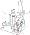
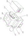
FIG. 1 is a schematic perspective view of an O-shaped joint strip production device;
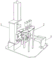
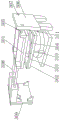
FIG. 2 is a schematic view of another angular configuration of an O-shaped joint strip production apparatus according to the present invention;
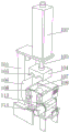
FIG. 3 is a schematic structural view of an internal mixer of the O-shaped sealing strip production equipment;
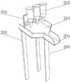
FIG. 4 is a perspective view of a feeding assembly of the O-shaped sealing strip production equipment;
FIG. 5 is a schematic diagram of a part of an internal mixer of the O-shaped sealing rubber strip production equipment;
FIG. 6 is a schematic diagram of a profiling assembly of an O-shaped sealing strip production device.
In the figure:
1. an internal mixer; 101. an internal mixer frame; 102. a lifting cylinder; 103. a lifting rod; 104. a sealing block; 105. a notch; 106. a turnover groove; 107. a banburying box; 108. a banburying roller; 109. a housing; 110. a driving machine; 111. a transmission gear; 112. a vibration machine; 113. a roll-over stand; 114. a turnover motor; 115. an elastic limit frame; 2. a feeding assembly; 201. a feed chute; 202. a storage tank; 203. a side mounting rod; 204. a discharge port; 205. a first stay plate; 206. a second stay plate; 3. profiling components; 301. an upper press plate; 302. a lower pressing plate; 303. a sealing frame; 304. an O-shaped groove; 305. a stabilizing block; 306. a stabilizing plate; 307. a stabilizing groove; 308. an electric telescopic rod; 309. a side plate; 310. a hydraulic lifter; 311. and a hydraulic lifting rod.
Detailed Description
In order that the above objects, features and advantages of the invention will be more clearly understood, a further description of the invention will be rendered by reference to the appended drawings and examples. It should be noted that, in the case of no conflict, the embodiments of the present application and the features in the embodiments may be combined with each other.
In the following description, numerous specific details are set forth in order to provide a thorough understanding of the present invention, however, the present invention may be practiced otherwise than as described herein, and therefore the present invention is not limited to the specific embodiments of the disclosure that follow.
Example 1
Referring to fig. 1-6, the present invention provides a technical solution: an O-shaped sealing adhesive tape production device comprises an internal mixer 1, wherein an internal mixing box 107 is arranged at the bottom of the internal mixer 1, two vibrating machines 112 are symmetrically arranged at one side of the internal mixing box 107, a roll-over stand 113 is arranged at one end of the internal mixing box 107, a roll-over motor 114 is arranged at one end of the roll-over stand 113, an elastic limit frame 115 is arranged at one side of the bottom of the roll-over motor 114, a profiling assembly 3 is arranged at one side of the internal mixer 1, an upper pressing plate 301 is arranged at the top of the profiling assembly 3, a lower pressing plate 302 is arranged at the bottom of the upper pressing plate 301, O-shaped grooves 304 are respectively formed in the inner sides of the upper pressing plate 301 and the lower pressing plate 302, a plurality of hydraulic lifting rods 311 are connected at the bottom of the lower pressing plate 302, a hydraulic lifter 310 is connected at one side of the upper pressing plate 301, a stabilizing block 305 is connected at one end of the upper pressing plate 301, a stabilizing plate 306 is connected at the outer side of the stabilizing block 305, the stabilizing plate 306 has a stabilizing slot 307 extending through the side surface, the overturning frame 113 is driven to rotate by the overturning motor 114, and then the banburying box 107 is driven to overturn, so that the banburying box 107 is reversely buckled, the colloid can be poured onto the lower pressing plate 302, high-frequency vibration can be generated by the vibrating machine 112 while the colloid is poured, the pouring speed is higher, after the colloid is poured onto the lower pressing plate 302, the upper pressing plate 301 is pushed to move to the position right above the lower pressing plate 302 by the electric telescopic rod 308, the stabilizing block 305 is inserted into the inner side of the stabilizing plate 306, then the hydraulic lifting rod 311 is controlled to be lifted by the hydraulic lifting rod 310, the lower pressing plate 302 is pushed to the bottom of the upper pressing plate 301 to be combined and connected, the shape of an O-shaped adhesive tape is extruded, and the adhesive tape forming process can be completed by the falling release of the hydraulic lifting rod 311.
As shown in fig. 4, a feeding assembly 2 is installed on the other side of the bottom of the internal mixer 1 through a bottom plate, a feeding groove 201 is fixedly installed at the top of the feeding assembly 2, three storage tanks 202 are arranged at the top of the feeding groove 201, and when the internal mixer is used for production, the opening and the closing of electromagnetic valves on the storage tanks 202 can be controlled by a computer so as to realize quantitative feeding, and materials discharged from the storage tanks 202 are conveyed to the inside of the internal mixing box 107 through the positions of the feeding groove 201 and a discharge hole 204.
As shown in fig. 4, the bottom of the side surface of the storage tank 202 is provided with electromagnetic valves, one end of the feeding tank 201 is provided with a discharge port 204, one end of the discharge port 204 points to the top of the banburying box 107, and the discharge port 204 can be communicated with the feeding tank 201 and can be used for conveying the raw materials in a pointing manner, so that the raw materials fall into the interior of the banburying box 107 completely to realize the later processing and production.
As shown in fig. 3, an internal mixer frame 101 is fixedly installed on one side of the internal mixer 1, a lifting cylinder 102 is installed at the top of the internal mixer frame 101, a lifting rod 103 is connected to the bottom of the lifting cylinder 102 and penetrates through the top of the internal mixer frame 101, a supporting effect can be provided through the internal mixer frame 101, a lifting adjusting effect can be provided by the lifting cylinder 102, and lifting control is completed by matching with the lifting rod 103.
As shown in fig. 3, the bottom of the lifting rod 103 is connected with a sealing block 104, two notches 105 are formed in the bottom of the sealing block 104, a turnover groove 106 is formed in one side of the internal mixer frame 101, the sealing block 104 can be sealed at the top of the internal mixing box 107 through lifting of the lifting rod 103, banburying work is facilitated by matching with the notches 105, and meanwhile the turnover groove 106 facilitates turnover and space providing effects.
As shown in fig. 3, the internal side of the internal mixing box 107 is provided with the internal mixing roller 108, one side of the internal mixing box 107 is provided with the shell 109, the internal side of the shell 109 is provided with the driving machine 110, one end of the driving machine 110 is connected with the transmission gear 111 in a meshed manner, the transmission gear 111 is connected with one end of the internal mixing roller 108 through a rotating shaft, and the internal mixing roller 108 can be connected with the driving machine 110 and the transmission gear 111 to realize a driving effect, thereby providing the internal mixing function.
As shown in fig. 4, a side mounting rod 203 is fixedly connected to a side of a storage tank 202, two ends of the side mounting rod 203 are fixedly connected to two sides of the top of a feeding tank 201, two first supporting plates 205 are fixedly connected to one end of the bottom of the feeding tank 201, a second supporting plate 206 is fixedly connected to the other end of the feeding tank 201, a side supporting and mounting function can be provided through the side mounting rod 203, an overall stable supporting property can be provided for the feeding tank 201 through the first supporting plates 205 and the second supporting plates 206, and an overall stable operation and use are guaranteed.
As shown in fig. 6, a sealing frame 303 is fixedly installed on the outer side of the lower pressing plate 302, a side plate 309 is fixedly installed at one end of the electric telescopic rod 308, sealing effect provided in the extrusion molding process can be facilitated through the sealing frame 303, uniformity of materials is ensured, and side support can be provided through the side plate 309 so that the electric telescopic rod 308 can run more stably.
An O-shaped sealing rubber strip production process of O-shaped sealing rubber strip production equipment comprises the following steps:
s1, firstly, main materials such as nitrile rubber, zinc oxide, stearic acid and the like are respectively placed into the storage tanks 202 for temporary storage.
S2, when the production is carried out, the opening and the closing of the electromagnetic valve on the storage tank 202 can be controlled by a computer so as to realize quantitative feeding operation, and materials discharged from the storage tank 202 are conveyed to the inside of the banburying box 107 through the positions of the feeding tank 201 and the discharging port 204.
S3, then the lifting rod 103 is controlled to fall through the lifting cylinder 102, the sealing block 104 is embedded into the inner side of the banburying box 107, the notch 105 is meshed and connected to the outer side of the banburying roller 108, and the banburying roller 108 can be driven to rotate by the driving machine 110 through the driving transmission gear 111.
S4, adding materials such as an accelerator and sulfur into the mixed sizing material through a feeding groove 201, and placing for a period of time for use, and heating and melting before production and molding.
S5, then, the overturning frame 113 is driven to rotate through the overturning motor 114, and then the banburying box 107 is driven to overturn, so that the banburying box 107 is reversely buckled, colloid can be poured onto the lower pressing plate 302 conveniently, and high-frequency vibration can be generated through the vibrating machine 112 while pouring, so that the pouring speed is higher.
S6, after being poured onto the lower pressing plate 302, the upper pressing plate 301 can be pushed to move to the position right above the lower pressing plate 302 by the electric telescopic rod 308, and the upper pressing plate is inserted into the inner side of the stabilizing plate 306 by the stabilizing block 305.
And S7, the hydraulic lifting rod 311 is controlled to be lifted by the hydraulic lifting device 310, so that the lower pressing plate 302 is pushed to the bottom of the upper pressing plate 301 to be combined and connected, the shape of the O-shaped adhesive tape is extruded, and the adhesive tape forming process can be completed by the falling and releasing of the hydraulic lifting rod 311.
The present invention is not limited to the above-mentioned embodiments, and any equivalent embodiments which can be changed or modified by the technical content disclosed above can be applied to other fields, but any simple modification, equivalent changes and modification made to the above-mentioned embodiments according to the technical substance of the present invention will still fall within the protection scope of the technical solution of the present invention.
Claims (9)
1. The production equipment of the O-shaped sealing rubber strip comprises an internal mixer (1), and is characterized in that: banbury mixer (1) installs banburying box (107), two jars (112) are installed to one side symmetry of banburying box (107), then install roll-over stand (113) in one end of banburying box (107), the one end of roll-over stand (113) is provided with roll-over motor (114), elasticity spacing (115) are installed to one side of the bottom of roll-over motor (114), profiling subassembly (3) are installed to one side of banbury mixer (1), top board (301) are installed at the top of profiling subassembly (3), holding down plate (302) are installed to the bottom of holding down plate (301), O type groove (304) have all been seted up to the inboard of holding down plate (301) and holding down plate (302), the bottom of holding down plate (302) is connected with a plurality of hydraulic lifting rods (311), the bottom of hydraulic lifting rods (311) is connected with hydraulic lifting ware (310), one side of holding down plate (301) is connected with two electric telescopic links (308), the one end of holding down plate (301) is connected with profiled block (305), stabilising plate (306) are seted up to the side of holding down plate (307).
2. The O-joint strip production apparatus of claim 1, wherein: the feeding device is characterized in that a feeding assembly (2) is arranged on the other side of the bottom of the internal mixer (1) through a bottom plate, a feeding groove (201) is fixedly arranged at the top of the feeding assembly (2), and three storage tanks (202) are arranged at the top of the feeding groove (201).
3. The O-joint strip production apparatus of claim 2, wherein: the side bottom of storage tank (202) all is provided with the solenoid valve, the one end of feed chute (201) is provided with discharge gate (204), the top of directional banburying box (107) of one end of discharge gate (204).
4. The O-joint strip production apparatus of claim 1, wherein: one side of banbury mixer (1) fixed mounting has banbury mixer frame (101), lift cylinder (102) are installed at the top of banbury mixer frame (101), the bottom of lift cylinder (102) is connected with lifter (103) and runs through in the top of banbury mixer frame (101).
5. The O-ring bead production apparatus of claim 4, wherein: the bottom of lifter (103) is connected with sealing block (104), two notch (105) have been seted up to the bottom of sealing block (104), upset groove (106) have been seted up to one side of banbury mixer frame (101).
6. The O-joint strip production apparatus of claim 1, wherein: banburying roller (108) are installed to the inboard of banburying box (107), shell (109) are installed to one side of banburying box (107), the inboard of shell (109) is provided with driving machine (110), the one end meshing of driving machine (110) is connected with drive gear (111), drive gear (111) are connected with the one end of banburying roller (108) through the pivot.
7. The O-joint strip production apparatus of claim 2, wherein: the side fixedly connected with side dress pole (203) of storage tank (202), the both ends fixed connection of side dress pole (203) are in the top both sides of feed tank (201), the bottom one end fixedly connected with of feed tank (201) two first fagging (205), the other end fixedly connected with second fagging (206) of feed tank (201).
8. The O-joint strip production apparatus of claim 1, wherein: the outside of holding down plate (302) is fixed mounting has sealed frame (303), the one end fixed mounting of electric telescopic handle (308) has curb plate (309).
9. An O-joint strip production process using the O-joint strip production apparatus according to any one of claims 1 to 8, comprising the steps of:
s1, firstly, main materials such as nitrile rubber, zinc oxide, stearic acid and the like are respectively placed into each storage tank (202) for temporary storage;
s2, when the production is carried out, opening and closing of an electromagnetic valve on the storage tank (202) can be controlled by a computer so as to realize quantitative feeding operation, and materials discharged by the storage tank (202) are conveyed to the inside of the banburying box (107) through the positions of the feed chute (201) and the discharge hole (204);
s3, subsequently, the lifting rod (103) is controlled to fall through the lifting cylinder (102), the sealing block (104) is embedded into the inner side of the banburying box (107), the notch (105) is meshed and connected to the outer side of the banburying roller (108), and the driving transmission gear (111) can be controlled through the driving machine (110) to drive the banburying roller (108) to rotate for banburying;
s4, adding materials such as an accelerator and sulfur into the mixed sizing material through a feeding groove (201), standing for a period of time for use, and heating and melting before production, molding and use;
s5, then, the overturning frame (113) is driven to rotate through the overturning motor (114), so that the banburying box (107) is driven to overturn, the banburying box (107) is reversely buckled, colloid can be poured onto the lower pressing plate (302) conveniently, and high-frequency vibration can be generated through the vibrating machine (112) while pouring, so that the pouring speed is higher;
s6, after being poured onto the lower pressing plate (302), the upper pressing plate (301) can be pushed to move to the position right above the lower pressing plate (302) through the electric telescopic rod (308), and the upper pressing plate is inserted into the inner side of the stabilizing plate (306) through the stabilizing block (305);
and S7, the hydraulic lifting rod (311) can be controlled to be lifted by the hydraulic lifting device (310) so that the lower pressing plate (302) is pushed to the bottom of the upper pressing plate (301) to be combined and connected, the shape of the O-shaped adhesive tape is extruded, and the adhesive tape forming process can be completed by the falling and releasing of the hydraulic lifting rod (311).
Priority Applications (1)
| Application Number | Priority Date | Filing Date | Title |
|---|---|---|---|
| CN202310537465.XA CN116252427B (en) | 2023-05-15 | 2023-05-15 | O-shaped sealing rubber strip production equipment and O-shaped sealing rubber strip production process |
Applications Claiming Priority (1)
| Application Number | Priority Date | Filing Date | Title |
|---|---|---|---|
| CN202310537465.XA CN116252427B (en) | 2023-05-15 | 2023-05-15 | O-shaped sealing rubber strip production equipment and O-shaped sealing rubber strip production process |
Publications (2)
| Publication Number | Publication Date |
|---|---|
| CN116252427A true CN116252427A (en) | 2023-06-13 |
| CN116252427B CN116252427B (en) | 2023-08-18 |
Family
ID=86686509
Family Applications (1)
| Application Number | Title | Priority Date | Filing Date |
|---|---|---|---|
| CN202310537465.XA Active CN116252427B (en) | 2023-05-15 | 2023-05-15 | O-shaped sealing rubber strip production equipment and O-shaped sealing rubber strip production process |
Country Status (1)
| Country | Link |
|---|---|
| CN (1) | CN116252427B (en) |
Cited By (1)
| Publication number | Priority date | Publication date | Assignee | Title |
|---|---|---|---|---|
| CN118636326A (en) * | 2024-05-30 | 2024-09-13 | 山东东都汽车部件股份有限公司 | Banbury mixer for rubber processing |
Citations (8)
| Publication number | Priority date | Publication date | Assignee | Title |
|---|---|---|---|---|
| US5183640A (en) * | 1990-08-29 | 1993-02-02 | Continental Aktiengesellschaft | Apparatus for producing rubber mixtures |
| CN204505664U (en) * | 2015-03-17 | 2015-07-29 | 广东利鑫智能科技有限公司 | A kind of silica gel forming machine |
| CN208428512U (en) * | 2018-06-26 | 2019-01-25 | 京山壹兴塑料制品有限公司 | A kind of discharging and extrusion molding apparatus for mixer |
| CN212826222U (en) * | 2020-08-19 | 2021-03-30 | 山西宇皓环保纸业有限公司 | Automatic feeding internal mixer for stone paper |
| CN216682841U (en) * | 2021-12-31 | 2022-06-07 | 温州市显兴新材料有限公司 | A novel banbury mixer for sole production |
| CN216941528U (en) * | 2021-11-11 | 2022-07-12 | 庐江县丰源橡胶密封件有限公司 | Large-size sealing ring production die arranged at intervals |
| CN218593370U (en) * | 2022-10-11 | 2023-03-10 | 唐山一诺高分子材料有限公司 | Top suspension type automatic turning plastic internal mixer |
| CN115926277A (en) * | 2022-12-06 | 2023-04-07 | 王晓东 | Preparation method of sealing rubber strip for piston oil groove of blast furnace gas holder |
-
2023
- 2023-05-15 CN CN202310537465.XA patent/CN116252427B/en active Active
Patent Citations (8)
| Publication number | Priority date | Publication date | Assignee | Title |
|---|---|---|---|---|
| US5183640A (en) * | 1990-08-29 | 1993-02-02 | Continental Aktiengesellschaft | Apparatus for producing rubber mixtures |
| CN204505664U (en) * | 2015-03-17 | 2015-07-29 | 广东利鑫智能科技有限公司 | A kind of silica gel forming machine |
| CN208428512U (en) * | 2018-06-26 | 2019-01-25 | 京山壹兴塑料制品有限公司 | A kind of discharging and extrusion molding apparatus for mixer |
| CN212826222U (en) * | 2020-08-19 | 2021-03-30 | 山西宇皓环保纸业有限公司 | Automatic feeding internal mixer for stone paper |
| CN216941528U (en) * | 2021-11-11 | 2022-07-12 | 庐江县丰源橡胶密封件有限公司 | Large-size sealing ring production die arranged at intervals |
| CN216682841U (en) * | 2021-12-31 | 2022-06-07 | 温州市显兴新材料有限公司 | A novel banbury mixer for sole production |
| CN218593370U (en) * | 2022-10-11 | 2023-03-10 | 唐山一诺高分子材料有限公司 | Top suspension type automatic turning plastic internal mixer |
| CN115926277A (en) * | 2022-12-06 | 2023-04-07 | 王晓东 | Preparation method of sealing rubber strip for piston oil groove of blast furnace gas holder |
Cited By (2)
| Publication number | Priority date | Publication date | Assignee | Title |
|---|---|---|---|---|
| CN118636326A (en) * | 2024-05-30 | 2024-09-13 | 山东东都汽车部件股份有限公司 | Banbury mixer for rubber processing |
| CN118636326B (en) * | 2024-05-30 | 2025-01-28 | 山东东都汽车部件股份有限公司 | Banbury mixer for rubber processing |
Also Published As
| Publication number | Publication date |
|---|---|
| CN116252427B (en) | 2023-08-18 |
Similar Documents
| Publication | Publication Date | Title |
|---|---|---|
| CN116252427B (en) | O-shaped sealing rubber strip production equipment and O-shaped sealing rubber strip production process | |
| CN204824828U (en) | Carousel formula multistation kneepiece briquetting machine | |
| CN112643856B (en) | Operation method of refractory brick forming die device | |
| CN205185012U (en) | Fragment of brick automatic molding device | |
| CN104987989A (en) | Rotating disc type multi-station distiller's yeast block pressing machine and pressing method | |
| CN219543790U (en) | Die structure for plastic products of plates and bars | |
| CN215320192U (en) | Glue injection filling device for long and narrow closed section bar | |
| CN215038517U (en) | Quick production device of rice straw brick | |
| CN206780804U (en) | A kind of solid-state foamed silica gel rolls composite integrated machine | |
| CN116332481B (en) | Glass production equipment and process for producing glass | |
| CN118559946A (en) | A production device for building insulation board | |
| CN206781057U (en) | A kind of foamed silica gel rolls coating machine | |
| CN221314580U (en) | Stamping forming device is used in building block production | |
| CN113696425B (en) | Injection mold for injection molding that application scope is big | |
| CN220049735U (en) | An automatic demoulding automobile stamping mold | |
| CN211683139U (en) | Centrifugal device for producing tire by using polyurethane elastomer mold | |
| CN219634611U (en) | Double-shaft vertical wet carbon rod forming machine | |
| CN220882761U (en) | Shaping device for refractory material production | |
| CN210940184U (en) | Electric injection molding machine | |
| CN2863433Y (en) | Special preparing apparatus for rubble roll | |
| CN220216695U (en) | Rare earth silicon magnesium alloy die | |
| CN217615778U (en) | Glue supply device of mould turning machine | |
| CN223173212U (en) | Vibration extrusion die for the production of small prefabricated components | |
| CN206011350U (en) | L shaped plate vibration-extrusion production line | |
| CN221164490U (en) | Material conveying device for glass manufacturing |
Legal Events
| Date | Code | Title | Description |
|---|---|---|---|
| PB01 | Publication | ||
| PB01 | Publication | ||
| SE01 | Entry into force of request for substantive examination | ||
| SE01 | Entry into force of request for substantive examination | ||
| GR01 | Patent grant | ||
| GR01 | Patent grant |