CN116231502A - An automatic temperature control switch cabinet and an automatic temperature control method - Google Patents
An automatic temperature control switch cabinet and an automatic temperature control method Download PDFInfo
- Publication number
- CN116231502A CN116231502A CN202310505346.6A CN202310505346A CN116231502A CN 116231502 A CN116231502 A CN 116231502A CN 202310505346 A CN202310505346 A CN 202310505346A CN 116231502 A CN116231502 A CN 116231502A
- Authority
- CN
- China
- Prior art keywords
- fan
- cabinet
- module
- temperature
- control module
- Prior art date
- Legal status (The legal status is an assumption and is not a legal conclusion. Google has not performed a legal analysis and makes no representation as to the accuracy of the status listed.)
- Granted
Links
Images
Classifications
-
- H—ELECTRICITY
- H02—GENERATION; CONVERSION OR DISTRIBUTION OF ELECTRIC POWER
- H02B—BOARDS, SUBSTATIONS OR SWITCHING ARRANGEMENTS FOR THE SUPPLY OR DISTRIBUTION OF ELECTRIC POWER
- H02B1/00—Frameworks, boards, panels, desks, casings; Details of substations or switching arrangements
- H02B1/56—Cooling; Ventilation
- H02B1/565—Cooling; Ventilation for cabinets
-
- G—PHYSICS
- G05—CONTROLLING; REGULATING
- G05D—SYSTEMS FOR CONTROLLING OR REGULATING NON-ELECTRIC VARIABLES
- G05D23/00—Control of temperature
- G05D23/19—Control of temperature characterised by the use of electric means
- G05D23/20—Control of temperature characterised by the use of electric means with sensing elements having variation of electric or magnetic properties with change of temperature
-
- H—ELECTRICITY
- H02—GENERATION; CONVERSION OR DISTRIBUTION OF ELECTRIC POWER
- H02B—BOARDS, SUBSTATIONS OR SWITCHING ARRANGEMENTS FOR THE SUPPLY OR DISTRIBUTION OF ELECTRIC POWER
- H02B1/00—Frameworks, boards, panels, desks, casings; Details of substations or switching arrangements
- H02B1/26—Casings; Parts thereof or accessories therefor
- H02B1/30—Cabinet-type casings; Parts thereof or accessories therefor
- H02B1/32—Mounting of devices therein
-
- Y—GENERAL TAGGING OF NEW TECHNOLOGICAL DEVELOPMENTS; GENERAL TAGGING OF CROSS-SECTIONAL TECHNOLOGIES SPANNING OVER SEVERAL SECTIONS OF THE IPC; TECHNICAL SUBJECTS COVERED BY FORMER USPC CROSS-REFERENCE ART COLLECTIONS [XRACs] AND DIGESTS
- Y02—TECHNOLOGIES OR APPLICATIONS FOR MITIGATION OR ADAPTATION AGAINST CLIMATE CHANGE
- Y02B—CLIMATE CHANGE MITIGATION TECHNOLOGIES RELATED TO BUILDINGS, e.g. HOUSING, HOUSE APPLIANCES OR RELATED END-USER APPLICATIONS
- Y02B30/00—Energy efficient heating, ventilation or air conditioning [HVAC]
Landscapes
- Engineering & Computer Science (AREA)
- Power Engineering (AREA)
- Physics & Mathematics (AREA)
- General Physics & Mathematics (AREA)
- Automation & Control Theory (AREA)
- Ventilation (AREA)
- Air Conditioning Control Device (AREA)
Abstract
本发明涉及电力设备通风控温技术领域,尤其涉及一种自动控温开关柜及自动控温的方法。提供一种自动控温开关柜,包括有柜体、底座、柜门、控制模组和元件安装板等;底座上安装柜体,柜体上铰接柜门,柜门上安装控制模组,柜体内固接元件安装板,元件安装板与柜体后侧壁之间留有间隙且形成左右两个安装室。本发明在柜体紧闭时采用间隔性的方式监测柜体内部的温度和湿度,每次监测获取柜体内的温度时,即使监测温度符合在常规温度区间内,也会调用风扇或半导体制冷模组Ⅰ进行短时间工作,将柜体内部温度维持在常规区间的同时,也大大的降低了维持柜内恒温的功耗。

The invention relates to the technical field of ventilation and temperature control of electric equipment, in particular to an automatic temperature control switch cabinet and an automatic temperature control method. An automatic temperature control switch cabinet is provided, including a cabinet body, a base, a cabinet door, a control module and a component mounting plate, etc.; the cabinet body is installed on the base, the cabinet door is hinged on the cabinet door, and the control module is installed on the cabinet door. The component mounting plate is fixed in the body, and there is a gap between the component mounting plate and the rear side wall of the cabinet to form two left and right mounting chambers. The present invention monitors the temperature and humidity inside the cabinet in an interval manner when the cabinet is tightly closed. When monitoring and obtaining the temperature in the cabinet each time, even if the monitored temperature is within the normal temperature range, the fan or semiconductor refrigeration module will be called Group I works for a short time to maintain the internal temperature of the cabinet within the normal range, and also greatly reduces the power consumption for maintaining a constant temperature inside the cabinet.
Description
技术领域technical field
本发明涉及电力设备通风控温技术领域,尤其涉及一种自动控温开关柜及自动控温的方法。The invention relates to the technical field of ventilation and temperature control of electric equipment, in particular to an automatic temperature control switch cabinet and an automatic temperature control method.
背景技术Background technique
开关柜的主要作用是在电力系统进行发电、输电、配电和电能转换的过程中,进行开合、控制和保护用电设备,由于开关柜是控制了用电设备的电路开合,柜内囊括了大量的电路开关器件,因此在电路接通时,相关的开关元器件发热是必不可少的,因此很有必要对柜体内部进行散热保障内部器件的正常运行。The main function of the switchgear is to open and close, control and protect the electrical equipment during the process of power generation, transmission, distribution and power conversion in the power system. Since the switchgear controls the circuit opening and closing of the electrical equipment, the inside of the cabinet A large number of circuit switching devices are included, so when the circuit is connected, it is necessary for the relevant switching components to generate heat, so it is necessary to dissipate heat inside the cabinet to ensure the normal operation of the internal devices.
在现有的开关柜内部散热方式主要有分为两种;第一种是采用自然通风的方式进行散热通风,机柜内部与外部空气对流循环,利用自然风对柜内设备进行换热的方式在一定程度上可以降低柜内温度,但对应的柜体需要开设通风孔洞,内外空气的交换会裹挟空气中的粉尘堆积在柜体内部,同时这样自然散热的效率十分有限;There are two main ways to dissipate heat inside the existing switchgear; the first is to use natural ventilation for heat dissipation and ventilation, the convection circulation between the inside and outside of the cabinet, and the use of natural wind to exchange heat for the equipment in the cabinet. To a certain extent, the temperature in the cabinet can be reduced, but the corresponding cabinet needs to be provided with ventilation holes, and the exchange of internal and external air will engulf the dust in the air and accumulate inside the cabinet. At the same time, the efficiency of natural heat dissipation is very limited;
第二种是采用相关的用电降温设备进行散热,较为常见是的风扇、热交换器和空调型实现对柜内温度控制,从柜体结构来说与之相关的用电降温设备需要长时间不停歇的运行,保障柜内温度维持在固定区间,虽然相比较于自然通风具有更好的降温通风效果,但是对应的能耗也将大幅度增加。The second is to use related electrical cooling equipment to dissipate heat. The more common types are fans, heat exchangers and air conditioners to control the temperature in the cabinet. From the cabinet structure, the related electrical cooling equipment takes a long time Non-stop operation ensures that the temperature inside the cabinet is maintained at a fixed range. Although it has a better cooling and ventilation effect than natural ventilation, the corresponding energy consumption will also increase significantly.
发明内容Contents of the invention
为了克服上述现有技术的缺点,提供一种自动控温开关柜及自动控温的方法。In order to overcome the above-mentioned shortcomings of the prior art, an automatic temperature control switch cabinet and an automatic temperature control method are provided.
本发明的技术方案是:一种自动控温开关柜,包括有柜体、底座、柜门、控制模组、元件安装板、风扇Ⅰ、风扇Ⅱ、风扇Ⅲ、风扇Ⅳ、温湿度传感器、排气筒、电动推杆、导向板、遮盖板和半导体制冷模组Ⅰ,底座上安装柜体,柜体上铰接柜门,柜门上安装控制模组,柜体内固接元件安装板,元件安装板与柜体后侧壁之间留有间隙且形成左右两个安装室,左安装室顶部安装风扇Ⅰ,左安装室底部安装风扇Ⅱ,柜门下部安装风扇Ⅲ,柜门上部安装风扇Ⅳ,所安装的四处位置的风扇Ⅰ、风扇Ⅱ、风扇Ⅲ、风扇Ⅳ的出风方向相互垂直,风扇Ⅰ、风扇Ⅱ、风扇Ⅲ、风扇Ⅳ均与控制模组通过导线连接,柜体右安装室顶部安装温湿度传感器,柜体右安装室顶部接通排气筒,柜体右安装室的顶壁分别固接电动推杆和导向板,导向板上滑动连接遮盖板,遮盖板与电动推杆的活动杆固接,且遮盖板能够滑动遮挡排气筒的通口,柜体内侧壁上安装半导体制冷模组Ⅰ,半导体制冷模组Ⅰ、电动推杆和温湿度传感器三者均与控制模组通过导线连接。The technical scheme of the present invention is: an automatic temperature control switch cabinet, including a cabinet body, a base, a cabinet door, a control module, a component mounting plate, a fan I, a fan II, a fan III, a fan IV, a temperature and humidity sensor, a row Inflator, electric push rod, guide plate, cover plate and semiconductor refrigeration module I, the cabinet body is installed on the base, the cabinet door is hinged on the cabinet body, the control module is installed on the cabinet door, the component mounting plate is fixed in the cabinet, and the component installation There is a gap between the panel and the rear side wall of the cabinet and two left and right installation rooms are formed. Fan I is installed on the top of the left installation room, fan II is installed on the bottom of the left installation room, fan III is installed on the lower part of the cabinet door, and fan IV is installed on the upper part of the cabinet door. The air outlet directions of fans I, fan II, fan III and fan IV installed at four positions are perpendicular to each other. Fan I, fan II, fan III and fan IV are all connected to the control module through wires. The top of the right installation room of the cabinet body The temperature and humidity sensor is installed, the top of the right installation room of the cabinet is connected to the exhaust pipe, the top wall of the right installation room of the cabinet is respectively fixed with the electric push rod and the guide plate, the guide plate is slid to connect the cover plate, and the cover plate and the electric push rod are connected. The movable rod is fixed, and the cover plate can slide to block the opening of the exhaust pipe. The semiconductor refrigeration module I is installed on the inner wall of the cabinet. The semiconductor refrigeration module I, the electric push rod and the temperature and humidity sensor are all connected with the control module. Connect by wire.
进一步的,还包括有局部降温组件,柜体的左安装室内设置局部降温组件;所述局部降温组件包括有第一电动导轨和半导体制冷模组Ⅱ,柜体的左安装室内纵向固接第一电动导轨,第一电动导轨上滑动连接半导体制冷模组Ⅱ,半导体制冷模组Ⅱ与元件安装板滑动接触,第一电动导轨与半导体制冷模组Ⅱ均和控制模组通过导线连接。Further, it also includes a local cooling assembly, and the local cooling assembly is arranged in the left installation room of the cabinet; the local cooling assembly includes the first electric guide rail and the semiconductor refrigeration module II, and the first The electric guide rail is slidingly connected to the semiconductor refrigeration module II on the first electric guide rail, and the semiconductor refrigeration module II is in sliding contact with the component mounting plate, and the first electric guide rail and the semiconductor refrigeration module II are connected to the control module through wires.
进一步的,还包括有清扫组件,柜体右安装室下部设置清扫组件;所述清扫组件包括有第二电动导轨、清扫刷和滑动挡板,柜体右安装室下部横向固接第二电动导轨,第二电动导轨与控制模组通过导线连接,第二电动导轨上滑动连接清扫刷,柜体下部开有一缺口,该缺口上滑动连接滑动挡板,清扫刷与滑动挡板配合接触。Further, it also includes a cleaning assembly, and the lower part of the right installation room of the cabinet body is provided with a cleaning assembly; the cleaning assembly includes a second electric guide rail, a cleaning brush and a sliding baffle, and the lower part of the right installation room of the cabinet body is horizontally fixed to the second electric guide rail , the second electric guide rail and the control module are connected by wires, the second electric guide rail is slidably connected to the cleaning brush, and there is a gap in the lower part of the cabinet body, and the sliding baffle is slidably connected to the gap, and the cleaning brush is in contact with the sliding baffle.
进一步的,还包括有收集组件,底座侧壁设置收集组件;所述收集组件包括有收集框、弹簧和触杆,底座侧壁滑动连接收集框,收集框位于滑动挡板下方,收集框和底座共同固接弹簧,收集框两侧开有斜边槽,滑动挡板底部对称固接触杆,触杆与斜边槽滑动接触。Further, it also includes a collection assembly, and the collection assembly is provided on the side wall of the base; the collection assembly includes a collection frame, a spring and a contact rod, and the side wall of the base is slidably connected to the collection frame, and the collection frame is located under the sliding baffle, and the collection frame and the base The springs are fixed together, the two sides of the collection frame are provided with inclined edge grooves, and the bottom of the sliding baffle is symmetrically fixed with contact rods, and the contact rods are in sliding contact with the inclined edge grooves.
进一步的,还包括有感应灯板,柜体内顶壁安装感应灯板,感应灯板与控制模组通过导线连接。Further, it also includes an induction lamp board, the induction lamp board is installed on the top wall of the cabinet, and the induction lamp board is connected with the control module through wires.
进一步的,还包括有加热模组和加湿抽湿一体模组,柜体内侧壁安装加热模组,柜体顶部设置加湿抽湿一体模组,加湿抽湿一体模组处于排气筒上方,加湿抽湿一体模组和加热模组二者均与控制模组通过导线连接。Further, it also includes a heating module and a humidification and dehumidification integrated module. The heating module is installed on the inner wall of the cabinet, and the humidification and dehumidification integrated module is installed on the top of the cabinet. The humidification and dehumidification integrated module is located above the exhaust pipe. Both the integrated dehumidification module and the heating module are connected to the control module through wires.
一种自动控温开关柜自动控温的方法,包括有以下步骤,A method for automatic temperature control of an automatic temperature control switch cabinet, comprising the following steps,
S1:确定柜内恒定温湿度数值区间S1: Determine the range of constant temperature and humidity values in the cabinet
设定柜体内部温湿度含有一个温度边界区间以及一个空气湿度区间,作为执行触发值,常规温度区间在17-27℃,记为K1,空气湿度区间在40-65%,记为L;Set the temperature and humidity inside the cabinet to include a temperature boundary interval and an air humidity interval as the execution trigger value. The normal temperature interval is 17-27°C, denoted as K 1 , and the air humidity interval is 40-65%, denoted as L;
S2:间歇性获取柜内温湿度数值S2: Intermittently obtain the temperature and humidity values in the cabinet
每1-3h通过温湿度传感器获取一次柜体内部温度和湿度数值,记录并存储在控制模组内,温度数值记为K,湿度数值记为L1;Obtain the temperature and humidity values inside the cabinet through the temperature and humidity sensor every 1-3 hours, record and store them in the control module, the temperature value is recorded as K, and the humidity value is recorded as L 1 ;
S3:工作执行S3: Work Execution
S3.1:控制模组调取当前K值并判断其是否在K1区间内,如果K<17,则控制模组调用风扇Ⅰ、风扇Ⅱ、风扇Ⅲ、风扇Ⅳ和加热模组工作,此时温湿度传感器实时监测,直到K属于K2即可停止升温工作,S3.1: The control module calls the current K value and judges whether it is within the K + 1 range. If K<17, the control module calls the fan I, fan II, fan III, fan IV and the heating module to work. The real-time monitoring of the temperature and humidity sensor will stop the heating work until K belongs to K2 .
如果K属于K1,则控制模组调用风扇Ⅱ和风扇Ⅳ一起或者单独调用半导体制冷模组Ⅰ工作15-30min即可停止,If K belongs to K 1 , the control module calls fan II and fan IV together or separately calls semiconductor cooling module I to work for 15-30 minutes to stop.
如果K>27,则控制模组调用风扇Ⅰ、风扇Ⅱ、风扇Ⅲ、风扇Ⅳ和半导体制冷模组Ⅰ工作,此时温湿度传感器实时监测,直到K属于K1即可停止工作;If K>27, the control module calls fan Ⅰ, fan Ⅱ, fan Ⅲ, fan Ⅳ and semiconductor refrigeration module Ⅰ to work. At this time, the temperature and humidity sensor monitors in real time until K belongs to K 1 and then stops working;
同时判断当前调取的K值比对上一次记录的K值差值是否超过上一次记录的K值50%,如果当前K值超过上一次记录的K值50%,但K属于K1,则将此次K值标记为异常值K2,At the same time, judge whether the difference between the currently retrieved K value and the last recorded K value exceeds 50% of the last recorded K value. If the current K value exceeds 50% of the last recorded K value, but K belongs to K 1 , then Mark this K value as an outlier K 2 ,
如果K>27,则将此次K值标记为异常值K2,控制模组同时调用半导体制冷模组Ⅰ、半导体制冷模组Ⅱ、第一电动导轨、风扇Ⅰ、风扇Ⅱ、风扇Ⅲ和风扇Ⅳ同时工作,此时温湿度传感器实时监测,直到K属于K1即可停止降温工作;If K>27, mark this K value as an abnormal value K 2 , and the control module simultaneously calls semiconductor cooling module I, semiconductor cooling module II, first electric guide rail, fan I, fan II, fan III and fan Ⅳ works at the same time, at this time, the temperature and humidity sensor monitors in real time, and the cooling work can be stopped until K belongs to K 1 ;
S3.2:控制模组调取当前L1值并判断其是否在L区间内,如果L1不属于L,则控制模组调用电动推杆工作,将遮盖排气筒的遮盖板移开,同时控制模组调用风扇Ⅰ、风扇Ⅱ、风扇Ⅲ、风扇Ⅳ开始工作,此时温湿度传感器实时监测,直到L1属于L即可停止工作;S3.2: The control module retrieves the current L 1 value and judges whether it is within the L interval. If L 1 does not belong to L, the control module calls the electric push rod to work, and removes the cover plate covering the exhaust pipe. At the same time, the control module calls Fan I, Fan II, Fan III, and Fan IV to start working. At this time, the temperature and humidity sensors monitor in real time, and stop working until L 1 belongs to L;
S3.3:如果采集K值后被连续的判定为异常值K2不低于3次,则控制模组将异常数据发送至控制台提出警示,如果异常值超过5次,则控制模组将关停相关的用电设备。S3.3: If the abnormal value K 2 is determined to be no less than 3 times continuously after collecting the K value, the control module will send the abnormal data to the console to raise a warning. If the abnormal value exceeds 5 times, the control module will Shut down related electrical equipment.
进一步的,所述步骤S3.2还包括以下步骤,在温湿度传感器实时监测下,控制模组调用风扇Ⅰ、风扇Ⅱ、风扇Ⅲ、风扇Ⅳ开始工作5-8min后,L1值未能进入到L区间内或者在5-8min的换气过程后L1值相比较于温湿度传感器实时监测的湿度值变化量低于20%情况下,控制模组需调用加湿抽湿一体模组协同风扇Ⅰ、风扇Ⅱ、风扇Ⅲ、风扇Ⅳ一起工作。Further, the step S3.2 also includes the following steps, under the real-time monitoring of the temperature and humidity sensor, after the control module calls fan I, fan II, fan III, and fan IV to start working for 5-8 minutes, the value of L1 fails to enter In the L interval or after the 5-8min ventilation process, when the L1 value changes less than 20% compared with the real-time monitoring humidity value of the temperature and humidity sensor, the control module needs to call the humidification and dehumidification integrated module to cooperate with the fan Ⅰ, fan Ⅱ, fan Ⅲ, fan Ⅳ work together.
有益效果是:本发明在柜体紧闭时采用间隔性的方式监测柜体内部的温度和湿度,每次监测获取柜体内的温度时,即使监测温度符合在常规温度区间内,均会调用一次风扇或半导体制冷模组Ⅰ进行短时间工作,将柜体内部温度维持在常规区间的同时,也大大的降低了维持柜内恒温的功耗;The beneficial effect is that the present invention monitors the temperature and humidity inside the cabinet in an interval manner when the cabinet is tightly closed, and every time the temperature in the cabinet is obtained through monitoring, even if the monitored temperature falls within the normal temperature range, it will be called once The fan or the semiconductor refrigeration module I work for a short time, while maintaining the internal temperature of the cabinet within a normal range, it also greatly reduces the power consumption for maintaining a constant temperature in the cabinet;
本发明在短暂的调用风扇工作时,使得柜体内部热量不再聚集于一点,热量会均匀分散在柜体内部所有的空气中,使得柜内温度上升更加缓慢,控温效果更佳,更加节能;When the present invention calls the fan for a short time, the heat inside the cabinet is no longer gathered at one point, and the heat will be evenly dispersed in all the air inside the cabinet, so that the temperature in the cabinet rises more slowly, the temperature control effect is better, and more energy-saving ;
本发明采用局部降温组件针对突发性的升温具有良好的控制效果,使得元件安装板上所安装的元件具有较好的稳定性,避免过热出现元件损坏;The invention adopts the local cooling component to have a good control effect on the sudden temperature rise, so that the components installed on the component mounting plate have better stability and avoid component damage due to overheating;
本发明增设升温异常的记录,对异常升温的及时处理,能够有效的保障开关柜的使用安全,保障设备的正常运行。The present invention adds a record of abnormal temperature rise, and timely processing of abnormal temperature rise can effectively guarantee the use safety of the switchgear and ensure the normal operation of the equipment.
附图说明Description of drawings
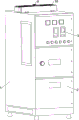
图1为本发明的立体结构示意图。Fig. 1 is a schematic diagram of the three-dimensional structure of the present invention.
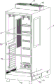
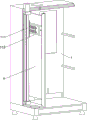
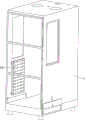
图2为本发明的去除柜门后的立体结构示意图。Fig. 2 is a schematic diagram of the three-dimensional structure of the present invention after the cabinet door is removed.
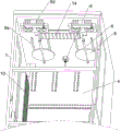
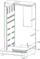
图3为本发明图2的局部立体结构示意图。Fig. 3 is a schematic diagram of a partial three-dimensional structure of Fig. 2 of the present invention.
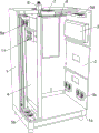
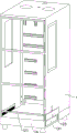
图4为本发明的柜体剖视后的立体结构示意图。Fig. 4 is a three-dimensional structural schematic diagram of the cabinet body of the present invention after sectioning.
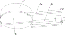
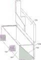
图5为本发明的排气筒、电动推杆和遮盖板立体结构示意图。Fig. 5 is a three-dimensional structural schematic diagram of the exhaust cylinder, the electric push rod and the cover plate of the present invention.
图6为本发明的局部降温组件立体结构示意图。Fig. 6 is a schematic perspective view of the three-dimensional structure of the local cooling component of the present invention.
图7为本发明的清扫组件立体结构示意图。Fig. 7 is a schematic perspective view of the three-dimensional structure of the cleaning assembly of the present invention.
图8为本发明的收集组件立体结构示意图。Fig. 8 is a schematic perspective view of the three-dimensional structure of the collection assembly of the present invention.
图9为本发明的收集组件脱离底座后的立体结构示意图。Fig. 9 is a schematic perspective view of the three-dimensional structure of the collection assembly of the present invention after it is detached from the base.
图10为本发明的柜体和加热模组立体结构示意图。Fig. 10 is a schematic diagram of the three-dimensional structure of the cabinet body and the heating module of the present invention.
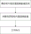
图11为本发明自动控温的方法流程图。Fig. 11 is a flow chart of the method for automatic temperature control of the present invention.
附图标记中:1-柜体,1a-底座,2-柜门,3-控制模组,4-元件安装板,5a-风扇Ⅰ,5b-风扇Ⅱ,5c-风扇Ⅲ,5d-风扇Ⅳ,6-温湿度传感器,7-排气筒,8-电动推杆,8a-导向板,9-遮盖板,10-半导体制冷模组Ⅰ,11-局部降温组件,111-第一电动导轨,112-半导体制冷模组Ⅱ,12-清扫组件,121-第二电动导轨,122-清扫刷,123-滑动挡板,123a-触杆,13-收集组件,131-收集框,132-弹簧,133-斜边槽,14-感应灯板,15-加热模组,16-加湿抽湿一体模组。Among the reference signs: 1-cabinet body, 1a-base, 2-cabinet door, 3-control module, 4-component mounting plate, 5a-fan Ⅰ, 5b-fan Ⅱ, 5c-fan Ⅲ, 5d-fan Ⅳ , 6-temperature and humidity sensor, 7-exhaust tube, 8-electric push rod, 8a-guide plate, 9-cover plate, 10-semiconductor refrigeration module Ⅰ, 11-local cooling component, 111-the first electric guide rail, 112-Pelactor refrigeration module II, 12-cleaning component, 121-second electric guide rail, 122-cleaning brush, 123-sliding baffle, 123a-touch rod, 13-collecting component, 131-collecting frame, 132-spring, 133-slope groove, 14-induction light board, 15-heating module, 16-humidification and dehumidification integrated module.
具体实施方式Detailed ways
以下结合附图和具体实施例对本发明作具体的介绍。The present invention will be described in detail below in conjunction with the accompanying drawings and specific embodiments.
实施例一Embodiment one
一种自动控温开关柜,如图1-图5所示,包括有柜体1、底座1a、柜门2、控制模组3、元件安装板4、风扇Ⅰ5a、风扇Ⅱ5b、风扇Ⅲ5c、风扇Ⅳ5d、温湿度传感器6、排气筒7、电动推杆8、导向板8a、遮盖板9和半导体制冷模组Ⅰ10,底座1a上安装柜体1,柜体1上铰接柜门2,柜门2呈现三段式的与柜体1铰接,最上层的柜门2上安装控制模组3,控制模组3作为微处理系统调度各个用电设备,包含微处理、远程通讯、信息处理以及逻辑运算等基础功能,柜体1内通过螺栓固定元件安装板4,所有的开关元件均安装在元件安装板4上,元件安装板4的顶部和底部均与柜体1之间存在间隙,元件安装板4与柜体1后侧壁之间留有间隙且形成左右两个安装室,左安装室顶部安装风扇Ⅰ5a,左安装室底部安装风扇Ⅱ5b,柜门2下部安装风扇Ⅲ5c,柜门2上部安装风扇Ⅳ5d,所安装的四处位置的风扇Ⅰ5a、风扇Ⅱ5b、风扇Ⅲ5c、风扇Ⅳ5d的出风方向相互垂直,风扇Ⅰ5a、风扇Ⅱ5b、风扇Ⅲ5c、风扇Ⅳ5d一同工作时,可以使得吹出的气流呈现循环的状态,加速内部空气流通,风扇Ⅰ5a、风扇Ⅱ5b、风扇Ⅲ5c、风扇Ⅳ5d均与控制模组3通过导线连接,由控制模组3进行统一调度,柜体1右安装室顶部安装温湿度传感器6用于监测柜体1内部的温度和湿度数值,柜体1右安装室顶部接通排气筒7,排气筒7可以交换柜体1内外的空气,柜体1右安装室的顶壁分别固接电动推杆8和导向板8a,导向板8a上滑动连接遮盖板9,遮盖板9与电动推杆8的活动杆固接,电动推杆8的活动杆推动着遮盖板9将排气筒7的通口遮盖,柜体1内侧壁上安装半导体制冷模组Ⅰ10,半导体制冷模组Ⅰ10可以对整个柜体1内部进行降温制冷,半导体制冷模组Ⅰ10、电动推杆8和温湿度传感器6三者均与控制模组3通过导线连接,温湿度传感器6将监测得到的数值传递到控制模组3。An automatic temperature control switch cabinet, as shown in Figures 1-5, includes a
如图4和图6所示,还包括有局部降温组件11,柜体1的左安装室内设置局部降温组件11;所述局部降温组件11包括有第一电动导轨111和半导体制冷模组Ⅱ112,柜体1的左安装室内纵向固接第一电动导轨111,第一电动导轨111上滑动连接半导体制冷模组Ⅱ112,半导体制冷模组Ⅱ112与元件安装板4滑动接触,半导体制冷模组Ⅱ112对接触的元件安装板4进行直接降温,在柜内温度上升的情况下防止元件安装板4上的开关元件局部过热,第一电动导轨111与半导体制冷模组Ⅱ112均和控制模组3通过导线连接。As shown in Figure 4 and Figure 6, it also includes a
如图2和图7所示,还包括有清扫组件12,柜体1右安装室下部设置清扫组件12;所述清扫组件12包括有第二电动导轨121、清扫刷122和滑动挡板123,柜体1右安装室下部横向通过螺栓固定安装第二电动导轨121,第二电动导轨121与控制模组3通过导线连接,第二电动导轨121上滑动连接清扫刷122,第二电动导轨121驱动着清扫刷122移动时,可以将柜体1内底部的灰尘或者日常维护时产生的垃圾扫在一起,柜体1下部开有一缺口,该缺口上纵向滑动连接滑动挡板123,滑动挡板123上有一斜面,清扫刷122与滑动挡板123的斜面配合接触,在控制模组3通过第二电动导轨121将清扫刷122驱动到极限位置后,清扫刷122与滑动挡板123接触,进而可以沿着滑动挡板123的斜面将之向上顶起,以此将柜体1下部的缺口打开,随即垃圾即可被扫出。As shown in Figure 2 and Figure 7, it also includes a cleaning
如图2、图8和图9所示,还包括有收集组件13,底座1a侧壁设置收集组件13;所述收集组件13包括有收集框131、弹簧132和触杆123a,底座1a侧壁滑动连接收集框131,收集框131位于滑动挡板123下方,收集框131和底座1a共同固接弹簧132,弹簧132用于保持收集框131处于弹出的状态,收集框131两侧开有斜边槽133,滑动挡板123底部对称焊接触杆123a,在触杆123a与斜边槽133的底边接触时,收集框131难以弹出,但当滑动挡板123上移时,收集框131的斜边槽133与触杆123a滑动接触并弹出,直到滑动挡板123完全上移,此时的垃圾也被清扫刷122扫出,同时掉落在收集框131内,清扫刷122返回后,滑动挡板123下落,再利用触杆123a沿着斜边槽133将收集框131压回。As shown in Fig. 2, Fig. 8 and Fig. 9, a
如图3所示,还包括有感应灯板14,柜体1内顶壁安装感应灯板14,感应灯板14与控制模组3通过导线连接,当柜门2打开时,感应灯板14自动亮起。As shown in FIG. 3 , it also includes an induction
如图2所示,还包括有加热模组15和加湿抽湿一体模组16,柜体1内侧壁安装加热模组15,柜体1顶部设置加湿抽湿一体模组16,加湿抽湿一体模组16处于排气筒7上方,加湿抽湿一体模组16和加热模组15二者均与控制模组3通过导线连接,加热模组15用于对柜体1内部的整体加热升温,加湿抽湿一体模组16控制进入柜体1内部的空气湿度。As shown in Figure 2, it also includes a
一种自动控温开关柜自动控温的方法,如图11所示,具体包括以下步骤,A method for automatic temperature control of an automatic temperature control switch cabinet, as shown in Figure 11, specifically includes the following steps,
S1:确定柜内恒定温湿度数值区间S1: Determine the range of constant temperature and humidity values in the cabinet
设定柜体1内部温湿度含有一个温度边界区间以及一个空气湿度区间,作为执行触发值,常规温度区间在17-27℃,记为K1,空气湿度区间在40-65%,记为L;Set the internal temperature and humidity of
S2:间歇性获取柜内温湿度数值S2: Intermittently obtain the temperature and humidity values in the cabinet
每2h通过温湿度传感器6获取一次柜体1内部温度和湿度数值,记录并存储在控制模组3内,温度数值记为K,湿度数值记为L1;Every 2h, the internal temperature and humidity values of the
S3:工作执行S3: Work Execution
S3.1:控制模组3调取当前K值并判断其是否在K1区间内,如果K<17,则控制模组3调用风扇Ⅰ5a、风扇Ⅱ5b、风扇Ⅲ5c、风扇Ⅳ5d和加热模组15工作,利用风扇Ⅰ5a、风扇Ⅱ5b、风扇Ⅲ5c、风扇Ⅳ5d将热空气循环吹到柜体1内部的所有角落,此时温湿度传感器6实时监测,直到K属于K1即可停止升温工作,以此可以降低柜体1内部因低温导致凝露的情况发生,确保设备稳定运行,S3.1: The
如果K属于K1,则控制模组3调用风扇Ⅱ5b、风扇Ⅳ5d和半导体制冷模组Ⅰ工作15min即可停止,由于K属于K1,则表示柜体1内部的温度处于正常的范围内,但是为了避免处于元件安装板4上的元件发热导致可能出现的局部升温,则可以进行施行短暂的降温措施,将热量分散到柜体1内部的各个角落,维持柜体1内部温度一致性,同时也可以保障内部温度始终处于常规温度的区间,使得降温设备无需长时间的运行If K belongs to K 1 , the
如果K>27,则控制模组3调用风扇Ⅰ5a、风扇Ⅱ5b、风扇Ⅲ5c、风扇Ⅳ5d和半导体制冷模组Ⅰ10工作,若有必要,则可以利用控制模组3调用电动推杆8工作,将遮盖排气筒7的遮盖板9移开,将柜体1内部高热空气排出,此时温湿度传感器6实时监测,直到K属于K1即可停止降温工作;If K>27, the
同时判断当前调取的K值比对上一次记录的K值差值是否超过上一次记录的K值50%,如果当前K值超过上一次记录的K值50%,但K属于K1,在日常的用电过程中,有可能会出现用电高峰期导致电路过载出现过热导致升温迅速的情况,此时则需要对此类情况进行标记,因此将此次K值标记为异常值K2,At the same time, judge whether the difference between the currently retrieved K value and the last recorded K value exceeds 50% of the last recorded K value. If the current K value exceeds 50% of the last recorded K value, but K belongs to K 1 , then In the daily power consumption process, there may be situations where the circuit is overloaded and overheated during the peak period of power consumption, resulting in rapid temperature rise. At this time, it is necessary to mark such situations, so this K value is marked as an abnormal value K 2 ,
如果K>27,则将此次K值标记为异常值K2,控制模组3同时调用半导体制冷模组Ⅰ10、半导体制冷模组Ⅱ112、第一电动导轨111和风扇Ⅰ5a、风扇Ⅱ5b、风扇Ⅲ5c、风扇Ⅳ5d同时工作,半导体制冷模组Ⅰ10对柜体1内部进行全局降温,第一电动导轨111带着半导体制冷模组Ⅱ112上下移动,并在移动的过程中对着元件安装板4进行降温,此时温湿度传感器6实时监测,直到K属于K1即可停止工作;If K>27, mark the K value this time as an abnormal value K 2 , and the
S3.2:控制模组3调取当前L1值并判断其是否在L区间内,如果L1不属于L,则表示柜体1内部空气极为干燥或者潮湿,不管是干燥或者潮湿,均会对开关元件造成影响,此时需要利用控制模组3调用电动推杆8工作,将遮盖排气筒7的遮盖板9移开,同时控制模组3调用风扇Ⅰ5a、风扇Ⅱ5b、风扇Ⅲ5c、风扇Ⅳ5d开始工作,循环替换柜体1内外的空气,此时温湿度传感器6实时监测,而在温湿度传感器6实时监测下,控制模组3调用风扇Ⅰ5a、风扇Ⅱ5b、风扇Ⅲ5c、风扇Ⅳ5d开始工作6min后,L1值未能进入到L区间内或者在6min的换气过程后L1值相比较于温湿度传感器6实时监测的湿度值变化量低于20%情况下,此时则有可能是外界空气本身湿度过高或者过于干燥,会导致交换后的空气始终无法达到既定区间,这样会使得风扇Ⅰ5a、风扇Ⅱ5b、风扇Ⅲ5c、风扇Ⅳ5d一直处于工作的状态,因此在固定的时间内监测到换气后的空气湿度依旧无法达到要求,则控制模组3需调用加湿抽湿一体模组16协同风扇Ⅰ5a、风扇Ⅱ5b、风扇Ⅲ5c、风扇Ⅳ5d一起工作,加湿抽湿一体模组16可以对通过排气筒7的空气进行增湿或抽湿处理,直到L1属于L即可停止换气工作;S3.2: The
S3.3:如果采集K值后被连续的判定为异常值K2不低于3次,表示长时间的用电过载,此时对于电路设施会造成极大的负担,发热所引起的电路安全隐患极为危险,因此控制模组3可以将异常数据发送至控制台提出警示,如果异常值超过5次,则控制模组3将关停相关的用电设备,或在人为干涉下有选择地关闭部分用电设备,以此来保障设备安全。S3.3: If the abnormal value K 2 is determined to be no less than 3 times continuously after collecting the K value, it means that the power consumption has been overloaded for a long time. At this time, it will cause a great burden on the circuit facilities and the circuit safety caused by heat The hidden danger is extremely dangerous, so the
上述实施例,只是本发明的较佳实施例,并非用来限制本发明实施范围,故凡以本发明权利要求所述内容所做的等效变化,均应包括在本发明权利要求范围之内。The foregoing embodiments are only preferred embodiments of the present invention, and are not intended to limit the scope of the present invention, so all equivalent changes made with the contents of the claims of the present invention should be included within the scope of the claims of the present invention .
Claims (8)
Priority Applications (1)
| Application Number | Priority Date | Filing Date | Title |
|---|---|---|---|
| CN202310505346.6A CN116231502B (en) | 2023-05-08 | 2023-05-08 | An automatic temperature control switch cabinet and an automatic temperature control method |
Applications Claiming Priority (1)
| Application Number | Priority Date | Filing Date | Title |
|---|---|---|---|
| CN202310505346.6A CN116231502B (en) | 2023-05-08 | 2023-05-08 | An automatic temperature control switch cabinet and an automatic temperature control method |
Publications (2)
| Publication Number | Publication Date |
|---|---|
| CN116231502A true CN116231502A (en) | 2023-06-06 |
| CN116231502B CN116231502B (en) | 2023-07-18 |
Family
ID=86569848
Family Applications (1)
| Application Number | Title | Priority Date | Filing Date |
|---|---|---|---|
| CN202310505346.6A Active CN116231502B (en) | 2023-05-08 | 2023-05-08 | An automatic temperature control switch cabinet and an automatic temperature control method |
Country Status (1)
| Country | Link |
|---|---|
| CN (1) | CN116231502B (en) |
Citations (7)
| Publication number | Priority date | Publication date | Assignee | Title |
|---|---|---|---|---|
| CN209608177U (en) * | 2019-04-02 | 2019-11-08 | 宇光电气有限公司 | A kind of intelligent switchboard |
| CN210008146U (en) * | 2019-05-10 | 2020-01-31 | 国网浙江缙云县供电有限公司 | Outdoor electrical cabinet with dehumidification, moisture-proof, heat dissipation and dust-proof |
| CN111478191A (en) * | 2020-04-16 | 2020-07-31 | 吴阳 | Electric automation control's heat dissipation regulator cubicle |
| CN212034507U (en) * | 2020-03-12 | 2020-11-27 | 张军军 | A new communication cabinet for communication equipment |
| CN216071544U (en) * | 2021-09-17 | 2022-03-18 | 固安鸿雄盛润农业科技有限公司 | Urban road garbage recycling device |
| CN216220647U (en) * | 2021-11-05 | 2022-04-08 | 兰州财经大学 | Multi-functional drawing table is used in art design indoor decoration |
| CN115156730A (en) * | 2022-05-13 | 2022-10-11 | 特固(江苏)塑料制品有限公司 | Wood laser cutting device with protection casing semi-closed |
-
2023
- 2023-05-08 CN CN202310505346.6A patent/CN116231502B/en active Active
Patent Citations (7)
| Publication number | Priority date | Publication date | Assignee | Title |
|---|---|---|---|---|
| CN209608177U (en) * | 2019-04-02 | 2019-11-08 | 宇光电气有限公司 | A kind of intelligent switchboard |
| CN210008146U (en) * | 2019-05-10 | 2020-01-31 | 国网浙江缙云县供电有限公司 | Outdoor electrical cabinet with dehumidification, moisture-proof, heat dissipation and dust-proof |
| CN212034507U (en) * | 2020-03-12 | 2020-11-27 | 张军军 | A new communication cabinet for communication equipment |
| CN111478191A (en) * | 2020-04-16 | 2020-07-31 | 吴阳 | Electric automation control's heat dissipation regulator cubicle |
| CN216071544U (en) * | 2021-09-17 | 2022-03-18 | 固安鸿雄盛润农业科技有限公司 | Urban road garbage recycling device |
| CN216220647U (en) * | 2021-11-05 | 2022-04-08 | 兰州财经大学 | Multi-functional drawing table is used in art design indoor decoration |
| CN115156730A (en) * | 2022-05-13 | 2022-10-11 | 特固(江苏)塑料制品有限公司 | Wood laser cutting device with protection casing semi-closed |
Also Published As
| Publication number | Publication date |
|---|---|
| CN116231502B (en) | 2023-07-18 |
Similar Documents
| Publication | Publication Date | Title |
|---|---|---|
| CN113784593B (en) | An assembled cooling cabinet and its working method | |
| CN212063201U (en) | High-efficient circulation heat dissipation high tension switchgear | |
| CN116231502B (en) | An automatic temperature control switch cabinet and an automatic temperature control method | |
| CN116313404A (en) | A Transformer Shell with Noise Reduction Function | |
| CN215009205U (en) | A switch cabinet heat monitoring and processing device | |
| CN208580957U (en) | A kind of low-voltage power supply electric cabinet | |
| CN212138185U (en) | Heat dissipation device of photovoltaic inverter | |
| CN109066379A (en) | A kind of heat dissipation air permeable type electric power distributing cabinet | |
| CN210016107U (en) | Drawer type direct current power distribution cabinet | |
| CN217336291U (en) | Multi-cold-source modular partitioned cooling equipment for data center | |
| CN213243340U (en) | Protection type cubical switchboard with heat dissipation function | |
| CN211017945U (en) | A 10KV high current switch cabinet | |
| CN213878849U (en) | Distribution project is with regulation formula switch board | |
| CN219592948U (en) | A dust-proof and moisture-proof frequency converter | |
| CN114421339A (en) | Isolating switch cabinet for power transmission and distribution transformer substation | |
| CN209748007U (en) | Heat dissipation formula low-voltage cabinet | |
| CN223157475U (en) | Ventilation and heat dissipation device of energy storage power station machine room | |
| CN114552450A (en) | Cubical switchboard heat dissipation window with automatic clearance function | |
| CN223540840U (en) | Three-phase locomotive air conditioner inverter | |
| CN220422311U (en) | Automatic integrated control box convenient to heat dissipation | |
| CN216016206U (en) | Heat radiation structure of large-current switch cabinet | |
| CN217425631U (en) | Constant voltage power supply compensation device for light source of xenon lamp light aging test equipment | |
| CN220978977U (en) | Laser cutting machine central control room convenient to accuse temperature | |
| CN220692651U (en) | Power distribution cabinet heat dissipation mechanism | |
| CN221862277U (en) | A high and low voltage switch cabinet |
Legal Events
| Date | Code | Title | Description |
|---|---|---|---|
| PB01 | Publication | ||
| PB01 | Publication | ||
| SE01 | Entry into force of request for substantive examination | ||
| SE01 | Entry into force of request for substantive examination | ||
| GR01 | Patent grant | ||
| GR01 | Patent grant | ||
| PE01 | Entry into force of the registration of the contract for pledge of patent right |
Denomination of invention: An automatic temperature control switch cabinet and an automatic temperature control method Granted publication date: 20230718 Pledgee: Bank of China Limited by Share Ltd. Cangzhou branch Pledgor: Guanglan Electric Equipment Co.,Ltd. Registration number: Y2026980004297 |
|
| PE01 | Entry into force of the registration of the contract for pledge of patent right |